Filipe Miguel Guerreiro Martins
Licenciado em Ciências da
Engenharia Electrotécnica e de Computadores
eVentos 2 - Autonomous sailboat control
Dissertação para obtenção do Grau de Mestre em Engenharia Electrotécnica e de Computadores
Orientador :
Prof. Doutor Luís Filipe dos Santos Gomes,
Professor Associado, Universidade Nova de Lisboa
Júri:
Presidente: Mário Fernando da Silva Ventim Neves
Arguente: Luís Filipe Figueira Brito Palma
iii
eVentos 2 - Autonomous sailboat control
Copyright cFilipe Miguel Guerreiro Martins, Faculdade de Ciências e Tecnologia, Uni-versidade Nova de Lisboa
Acknowledgements
I would like to start by thanking my dissertation supervisor, Prof. Luis Gomes for all his help, patience and support when i needed and for putting up with my work methods. I would also like to express my gratitude to my laboratory colleagues Marcelo Rodrigues and Flávio Gil for all their support and help.
My next acknowledgements go to all my academic colleagues and friends that made my academic path much more interesting and worthwhile, namely Pedro Cunha, Pedro Sardinha, Carlos Ribeiro, Diogo Morgado, Jo˜ao Silva, Nuno Pereira, Hugo Serra, Pedro Leit˜ao, José Vieira, António Furtado, Ricardo Mendonça, Pedro Mota and many, many more.
I’d like to also acknowledge all my friends and life-time partners from the university’s archery team, for being fun (most of the times even moronic) and for all their support when i really needed it.
Abstract
Sailboat navigation started as a way to explore the world. Even though performance is significantly lower than that of a motorboat, in terms of resources, these vessels still are the best low-cost solutions. On the past, navigation depended greatly on estimates or on the stars. Nowadays it depends on precise data provided by a variety of electronic devices, independent from the user’s location.
Autonomous sailboats are vessels that use only the wind for propulsion and have the capacity to control its sails and rudders without human intervention. These particu-larities give them almost unlimited autonomy and a very valuable ability to fulfill long term missions on the sea, such as collecting oceanographic data, search and rescue or surveillance.
This dissertation presents a fuzzy logic controller for autonomous sailboats based on a proposed set of sensors, namely a GPS receiver, a weather meter and an electronic compass. Following a basic navigation approach, the proposed set of sensors was studied in order to obtain an effective group of variables for the controller’s fuzzy sets, and rules for its rule base. In the end, four fuzzy logic controllers were designed, one for the sail (to maximize speed) and three for the rudder (in order to comply with all navigation situations). The result is a sailboat control system capable of operation in a low cost platform such as an Arduino prototyping board. Simulated results obtained from a data set of approximately 100 tests to each controller back up the theory presented for the controller’s operation, since physical experimentation was not possible.
Resumo
A navegaç˜ao à vela estreou-se como uma maneira de explorar o mundo. Mesmo tendo um rendimento bastante menor que o de um barco a motor, estes navios continuam a ser a melhor soluç˜ao de baixo custo no que toca ao gasto de recursos. No passado, a navegaç˜ao dependia grandemente de estimativas e da leitura das estrelas, hoje em dia depende de dados precisos fornecidos por uma variedade de aparelhos electrónicos, in-dependentemente da localizaç˜ao do utilizador.
Veleiros autónomos s˜ao veículos que apenas utilizam o vento como forma de propuls˜ao, com capacidade de controlar as suas velas e lemes sem ajuda humana. Estas particula-ridades da˜o autonomia quase ilimitada e uma valiosa habilidade de cumprirem misso˜es
longas, tais como recolha de dados oceanográficos, busca e salvamento ou vigilância. Esta dissertaç˜ao apresenta um controlador difuso para veleiros autónomos baseado num conjunto proposto de sensores, nomeadamente um receptor GPS, anemómetro, cata-vento e um sensor de bússola. Seguindo uma abordagem baseada em navegaç˜ao simples, o conjunto de sensores proposto foi estudado de forma a obter um grupo eficaz de variá-veis para os conjuntos difusos do controlador, e de regras para a sua base de regras. No final, quatro controladores de lógica difusa foram projectados, um para a vela (de forma a maximizar a velocidade) e três para o leme (de forma a cumprir todas as situaço˜es
pos-síveis de navegaça˜o). O resultado foi a criaç˜ao de um sistema de controlo para navegaç˜ao à vela capaz de actuar numa plataforma de baixo custo, uma placa de prototipagem Ar-duino. Os resultados de simulaç˜ao obtidos de um conjunto de dados de aproximada-mente 100 testes a cada controlador apoiam a teoria apresentada para a operaç˜ao deste controlador, visto que a experimentaç˜ao em ambiente físico na˜o foi possível.
Contents
Acknowledgements v
Abstract vii
Resumo ix
List of Figures xv
List of Tables xix
Abbreviations xxi
1 Introduction 1
1.1 Motivation . . . 1
1.2 Objectives and contributions . . . 2
1.3 Dissertation Outline . . . 2
2 Related work 5 2.1 FASt - FEUP Autonomous Sailboat . . . 6
2.1.1 Hardware . . . 6
2.1.2 Software . . . 8
2.2 Fuzzy logic control on autonomous sailing systems . . . 9
2.2.1 System Architecture . . . 9
2.2.2 Fuzzy Control System . . . 10
2.2.3 Results and conclusions . . . 12
3 Supporting Concepts 15 3.1 Basics of Sailing . . . 15
3.1.1 The vessel . . . 15
3.1.2 The use of sails . . . 17
xii CONTENTS
3.2 Fuzzy Control . . . 21
3.2.1 An Introduction . . . 21
3.2.2 Applications . . . 22
3.2.3 Essential characteristics . . . 23
3.2.4 Fuzzy logic controller architecture . . . 24
4 Software and Hardware 29 4.1 Arduino . . . 29
4.1.1 Hardware . . . 30
4.2 Proposed sensors for the project . . . 31
4.2.1 Weather meter . . . 31
4.2.2 CMPS10 Tilt Compensated Magnetic Compass . . . 32
4.2.3 EM-406A SiRF III GPS Receiver with Antenna . . . 32
4.3 Available sensors and emulators . . . 34
4.3.1 Simulation platform . . . 34
4.3.2 PIC-Arduino interface . . . 35
4.4 Xfuzzy . . . 35
5 Proposed controller 37 5.1 Transition between manual and automatic control . . . 38
5.2 Designed controller . . . 41
5.3 Controller Variables . . . 42
5.3.1 Wind Alignment . . . 42
5.3.2 Directional Alignment . . . 44
5.4 Control structure . . . 46
5.4.1 Sail . . . 47
5.4.2 Rudder . . . 50
5.4.3 Rudder decider structure . . . 55
5.4.4 Goal approaching . . . 58
6 Experimental results 63 6.1 Xfuzzy- Arduino integration . . . 64
6.2 Experimental results and analysis . . . 64
6.2.1 Sail . . . 65
6.2.2 Favorable Wind . . . 68
6.2.3 Tack Left . . . 71
6.2.4 Tack Right . . . 73
7 Conclusions and future work 77 7.1 Conclusions . . . 77
CONTENTS xiii
Bibliography 81
List of Figures
2.1 FEUP Autonomous Sailboat [AC09]. . . 6
2.2 FASt’s electronic system, adapted from [AC09]. . . 7
2.3 FASt’s software organization, adapted from [AC09]. . . 8
2.4 (a) - Robbe Atlantis yacht; (b) - Detailed system architecture; . . . 10
2.5 Fuzzy sets for rudder input. . . 10
2.6 Fuzzy set for rudder output. . . 11
2.7 Fuzzy set for sail input. . . 11
2.8 Fuzzy set for sail output. . . 12
2.9 Test runs for turning against and in favor of the wind respectively with 2 second time intervals. . . 13
3.1 Main sailboat equipment [Boa] and side terms, viewed from above. . . 16
3.2 Killer Whales Yacht. . . 17
3.3 Experienced winds [Ass]. . . 17
3.4 Lift and aerodynamic force created by the wind [Saib]. . . 19
3.5 Sailing techniques 1 [Sal96]. . . 19
3.6 Sailing techniques 2 [Sal96]. . . 20
3.7 Sailing techniques 3 [Cat, Sal96]. . . 21
3.8 Fuzzy logic controller [Alo]. . . 24
3.9 Different membership function types: (a) - Triangular ; (b) - Trapezoidal; (c) - Bell-shaped; (d) - Singleton; . . . 25
3.10 Fuzzification stage for crisp inputs [Yal]. . . 25
3.11 Mamdani two input, two rule inference system [Kna]. . . 27
4.1 Arduino Mega 2560 board [Ban]. . . 30
4.2 Proposed sensors: a)Weather Meter [Sysb]; b)Compass Module [PTRb]; c)GPS Module [PTRa]; . . . 33
4.3 Sensorial emulation setup [Gil13]. . . 34
xvi LIST OF FIGURES
5.1 Signal generated when the remote controller is off. . . 37
5.2 Signal generated when the remote controller is off. . . 38
5.3 Signal generated when the remote controller is on (noise is irrelevant in this case as it is only generated from the RF waves into the oscilloscope). . 38
5.4 Transition between manual and remote control. . . 39
5.5 Different characteristics in the controller’s signal. . . 39
5.6 a)Counter implementation flowchart; b)Transition strategy flowchart; . . . 40
5.7 Pin scheme used for transition between controls. . . 41
5.8 General layout of inputs and outputs of the controller system. . . 42
5.9 New set of variables used for sail and rudder control. . . 42
5.10 Wind alignment value range. . . 43
5.11 Wind alignment algorithm confirmation. . . 43
5.12 Original graphical projection of the intended course. . . 44
5.13 Modified graphical projection of the intended course. . . 44
5.14 Rectangular to polar coordinate conversion, adapted from [Vau]. . . 45
5.15 Directional alignment value range. . . 45
5.16 Updated layout of the controller system. . . 47
5.17 Trapezoid point specification. . . 47
5.18 Roll’s fuzzy set. . . 48
5.19 Wind Speed’s fuzzy set. . . 48
5.20 Wind Alignment’s fuzzy set. . . 49
5.21 Sail’s fuzzy set. . . 49
5.22 Directional Alignment’s fuzzy set. . . 51
5.23 Boat Speed’s fuzzy set. . . 51
5.24 Rudder’s fuzzy set. . . 52
5.25 State machine of the rudder decider structure. . . 56
5.26 Potentially used sailing area, defined in the beginning of the course. . . . 57
5.27 Radius from both the objective buoy and distance to the vessel. . . 58
5.28 a) Finish line half planes identification; b) Lines at right angles to the finish line; . . . 59
5.29 Zone division for finish line detection. . . 60
6.1 Experimental results for the sail controller part 1. . . 65
6.2 Experimental results for the sail controller part 2. . . 65
6.3 Experimental results for the sail controller part 3. . . 66
6.4 Experimental results for the sail controller part 4. . . 66
6.5 Experimental results for the sail controller part 5. . . 67
6.6 Experimental results for the favorable wind controller part 1. . . 68
6.7 Experimental results for the favorable wind controller part 2. . . 68
6.8 Experimental results for the favorable wind controller part 3. . . 69
LIST OF FIGURES xvii
6.10 Experimental results for the favorable wind controller part 5. . . 70
6.11 Experimental results for the tack left controller part 1. . . 71
6.12 Experimental results for the tack left controller part 2. . . 71
6.13 Experimental results for the tack left controller part 3. . . 72
6.14 Experimental results for the tack left controller part 4. . . 72
6.15 Experimental results for the tack right controller part 1. . . 73
6.16 Experimental results for the tack right controller part 2. . . 73
6.17 Experimental results for the tack right controller part 3. . . 74
6.18 Experimental results for the tack right controller part 4. . . 74
List of Tables
2.1 Rudder rule base. . . 11
3.1 Applications of fuzzy logic control, as seen in [YLZ95] page 6. . . 22
4.1 Arduino Mega 2560 features. . . 31
4.2 RMC Data Format, adapted from [ST]. . . 33
5.1 Test results for acquiring efficient threshold values. . . 40
5.2 Confirmation examples for the directional alignment algorithm. . . 46
5.3 Trapezoid values for each fuzzy set on the sail controller. . . 50
5.4 Fuzzy rules for the sail inference system. . . 50
5.5 Trapezoid values for each fuzzy set on the rudder controllers. . . 52
5.6 Fuzzy rules for the rudder inference system - favorable wind situation. . . 53
5.7 Fuzzy rules for the rudder inference system - left tack situation. . . 54
5.8 Fuzzy rules for the rudder inference system - right tack situation. . . 55
7.1 Available router model research. . . 79
A.1 Sail controller experimental results. . . 87
A.2 Rudder: Favorable Wind controller experimental results. . . 90
A.3 Rudder: Tack Right controller experimental results. . . 92
Abbreviations
COM ComponentObjectModel CPU CentralProcessingUnit
FEUP Faculdade deEngenharia daUniversidade doPorto FPGA FieldProgrammableGateArray
GPS GlobalPositioningSystem I2C InterIntegratedCircuit
ICSP InCircuitSerialProgramming JRE JavaRuntimeEnvironment
NMEA NationalMaritimeElectronicsAssociation PCB PrintedCircuitBoard
PWM PulseWidthModulation RAM RandomAccessMemory RF RadioFrequency
RMB RecommendedMinimum Navigation Information RMC RecommendedMinimumData
SPI SerialPeripheralInterface SSI SerialSynchronousInterface
1
Introduction
1.1
Motivation
Developing an autonomous sailboat is a relatively complex task, from the vessel’s me-chanical construction to implementing its electronic systems. Sailing can be viewed as a complex problem dependent on unpredictable environmental conditions and interre-lated variables such as the designated course, wind (direction and speed) and sea state. In conventional sailing, the sailor controls the rudder according to the desired course of action and the sail to maximize velocity. For a given course, there is always an optimum angle between the sail and direction of the wind to maximize the speed of the vessel.
1. INTRODUCTION 1.2. Objectives and contributions
1.2
Objectives and contributions
Completely autonomous navigation requires other tasks such as reaching a pre-determined set of geographic points, maintaining the vessel inside a delimited area or achieving minimal time to pass through a designated course. Various works have been published [ATA02, SP08, EK06] and from these efforts resulted autonomous sailboats demonstrat-ing these technologies, appeardemonstrat-ing in competitions such as Microtransat [Micc]. In Novem-ber 2010, a meeting between various Portuguese academic institutions culminated in the idea to start a new maritime robotic competition, MAROCUP (MAritime RObotic CUP). This dissertation’s main objective is to design, simulate and implement the general archi-tecture for UNL’s sailboat controller. To achieve this objective, comprehension of how a sailboat works is necessary to obtain an expert’s view of the system. The strategy used was independent control of rudder and sail, for decreased complexity and the type of control used was fuzzy logic. This type of control was chosen mainly because of its abil-ity to design and simulate a system without a proper description. In this case, the sailboat system had no description to start working with. Rudder control needed more than one controller since steering a sailboat is wind dependent, making it a delicate and complex system, as seen ahead. A secondary objective of this dissertation was improving the work already done in this project [Gil13]. This objective was achieved by designing a method for transition between the vessel’s automatic and manual control modes and by various suggestions done in chapter 7.
1.3
Dissertation Outline
Besides this introductory chapter, this dissertation is organized in six more chapters. Chapter 2 gives a small introduction about various other projects developed in the area. A mora detailed description is given of two points of interest: an autonomous sail-boat system and a fuzzy logic controller for sailing systems. The sailsail-boat was designed in FEUP and its hardware and software specifications are presented. The fuzzy control system is described and it is important to notice that it was experimented on a vessel much similar to the one designed by FEUP.
Chapter 3 presents the main concepts related with the work done on this dissertation. First, a basic introduction to a sailboat’s most important components, use of sails and techniques used is presented. A short introduction about fuzzy control is also given, presenting some applications, its essential characteristics and how a typical inference system works.
1. INTRODUCTION 1.3. Dissertation Outline
Xfuzzy design tool is described.
Chapter 5 describes all the developed work. After a general layout, a description of the transition method between automatic and manual control is given before presenting the designed controller. This controller is thoroughly described, its variables, control strategies, methods for changing strategies and two techniques for approaching a finish point.
Chapter 6 presents experimental results obtained from both Xfuzzy’s simulation and Arduino code for the designed controllers. These experimental results are obtained using MATLAB to graphically obtain representations of the the data sets.
2
Related work
A sailboat is a strongly non-linear system that has been given proof to be easily con-trolled. Its mechanical design comes from hundreds of years of evolution concerning mainly the efficiency and reliability of the vehicle and its ease of use by human opera-tors. Out of many, this chapter introduces an existing autonomous sailboat system and also a fuzzy logic controller designed for use in sailboats.
2. RELATED WORK 2.1. FASt - FEUP Autonomous Sailboat
2.1
FASt - FEUP Autonomous Sailboat
The autonomous sailboat FASt shown in figure 2.1 is an unmanned vessel 2,5 meters wide, designed and developed in FEUP (Faculdade de Engenharia da Universidade do Porto, Portugal) as an extra-curricular project by students of master’s degree in electrical engineering. Its rig is similar to that of real manned sailboat and it entered the first edition of the World Robotic Sailing Championship in 2008[OGfiC].
Figure 2.1: FEUP Autonomous Sailboat [AC09].
Its electronic control and navigation system is based on a reconfigurable platform con-taining a FPGA (Field Programable Gate Array) executing the operating system uCLinux in a Microblaze processor. Besides the CPU and the peripherals necessary to the compu-tational system, the FPGA implements a set of dedicated interface and processing units that realize various communication processes with the peripherals (sensors and actua-tors). These modules give relevant and pre-processed data do the CPU from each sensor and generate the control signals necessary to act on the electrical motor actuators) [AC09].
2.1.1 Hardware
FASt’s electronic system was built around a FPGA based commercial platform, which implements a computational system. Besides the incorporated sensors and actuators, the vessel has an Ethernet router with wireless connection, remote radio controller and an IRIDIUM modem for short data message communication when sailing in open sea. The electric power necessary onboard is provided be a 45 Peak-Watt solar panel, two lithium-ion with a total capacity of 190 Watt/hour and a commercial module which integrates the battery charger and power supply.
2. RELATED WORK 2.1. FASt - FEUP Autonomous Sailboat
A motherboard aggregates all the electronic components used in interfacing with the FPGA. It also offers a set of connectors where all of FASt’s sensors and actuators are linked. Also, it is included a SD card reader which is used for data registry and non-volatile data such as real time clock, used to maintain the main state variables and to provide the current time whenever the GPS module is put in low-consumption mode.
Figure 2.2: FASt’s electronic system, adapted from [AC09].
The computational system was implemented around a Spartan3E 1200 (Suzaku SZ130 [AT]) FPGA. The platform has 32 Mega-Bytes for SDRAM, 8 Mega-Bytes for flash mem-ory, Ethernet connection and a serial port for the data console. The flash memory main-tains an image of the operating system and the FPGA configuration. This information can be refreshed from the operating system’s shell. There is a total of 86 terminals directly connected to FPGA pins, which permits the direct connection of various peripherals.
2. RELATED WORK 2.1. FASt - FEUP Autonomous Sailboat
2.1.2 Software
The software component was developed in C, using standard Linux libraries also avail-able in uCLinux. The navigation and control processes are divided in various concurrent processes communicating between themselves through UDP sockets, as shown in figure 2.3. The adoption of an operating system based in Linux allows an highly efficient soft-ware development environment. Any of the implemented programs can be compiled and executed in any Linux machine that is accessible via TCP/IP to FASt’s onboard computer.
Figure 2.3: FASt’s software organization, adapted from [AC09].
To support the validation and development of the software, a FASt emulator was de-veloped in laboratory replacing the layer that implements the hardware interface. The emulator (vaphw-sim) includes a non-linear dynamic model of the vessel, which simu-lates its behavior according to the wind and the sail and rudder positioning commands. This is an essential step to allow the independent development of the software part, free from the hardware and to limit the number of necessary field tests, which require signif-icant logistics, resource and time spending.
2. RELATED WORK 2.2. Fuzzy logic control on autonomous sailing systems
and also the reproduction of saved data during a navigation mission, real or simulated.
2.2
Fuzzy logic control on autonomous sailing systems
Many different systems are available that can assist in the steering of a sailboat. The most popular commercial systems are autopilots and wind vanes and both systems can keep the vessel on a predefined course. While the autopilot keeps the vessel on course using compass data, the wind vanes keep the course using the wind. Both systems control the rudder but have no influence on the sail sheets, these need to be adjusted manually. Many methods for rudder control exist, fuzzy [ASC97, Van97] as well as nonfuzzy [War91] but none of them cover sail control.
The system proposed in this section is able to control all the manoeuvres of an au-tonomous sailboat. A separate software module is responsible for weather routing and delivering directions for the actual vessel position and weather conditions in real time. If the vessel’s direction deviates, the system adjusts the rudder in order to achieve the desired course. A second control system assures that there is flow in the sails in order to get speed. It also controls the tilting of the vessel, depending on the speed and direction of the wind. The main aim of this system is to imitate the behavior of an experienced hu-man sailor. Therefore it is not limited to a specific vessel, but applicable to every common type of sailboat. Fuzzy logic is used to control both actuators for sail and rudder. This is a very suitable method for transforming expert’s knowledge into a computer program in form of if-then rules, as presented in [SPJ07], which will be described in the following sub-sections.
2.2.1 System Architecture
Experimenting the system was carried out on the 1,38m yacht model "Robbe Atlantis" (figure 2.4 (a)) under real-world conditions. The vessel won the First Microtransat Chal-lenge [Micc] for autonomous sailboats in Toulouse, France in June 2006. The aim was to demonstrate completely autonomous sailing, where routing and navigation have to run automatically on the vessel. The "Robbe Atlantis" is usually used as a remote con-trolled sailboat. For testing purposes it was additionally equipped with various sensors to measure the environmental conditions. A program called "abstractor" running on the boat gathers sensor data and transforms it into semantically useful information for the routing software. The modular architecture of the system is shown in figure 2.4 (b).
2. RELATED WORK 2.2. Fuzzy logic control on autonomous sailing systems
(a) (b)
Figure 2.4: (a) - Robbe Atlantis yacht; (b) - Detailed system architecture;
2.2.2 Fuzzy Control System
In sailing, different persons are able to control the rudder and sail separately, without communication. Therefore in the presented system, two independent working control loops are responsible for the rudder and sail actuators. The rudder controller keeps the vessel on a predefined course given by the routing software. The sail controller avoids capsize and assures that there is enough flow in the sails, giving propulsion power to the vessel. Both actuators should be controlled fast but smoothly, without leaps or oversteer-ing. Two Sugeno type fuzzy inference systems were used to reach this goal. Trapezoid fuzzy sets are used as inputs and singletons represent output variables. Defuzzification is done by the center of gravity of singletons method. The execution of the system was identified by experimentation and has to be adapted for every type of vessel.
The current vessel direction and desired direction are the input data for the rudder control circuit. The difference between these two give the necessary course correction which enters directly into the fuzzy system (desired direction). To avoid oversteering, the angular velocity of the vessel flows as an additional input variable (turn). The fuzzy sets representing the linguistic terms of these input variables are shown in figure 2.5.
2. RELATED WORK 2.2. Fuzzy logic control on autonomous sailing systems
The rudder control output is the change of the rudder position. The fuzzy variable rudder change (in percentage) contains five singletons representing the linguistic terms of the variable (figure 2.6).
Figure 2.6: Fuzzy set for rudder output.
The rule base in table 2.1 of the rudder control systems contains 15 rules in the form IFdesired directionIS x ANDturnIS y THENrudder changeIS z .
Table 2.1: Rudder rule base.
Rudder change Turn
Desired direction Left Neutral Right Strong left Left Strong left Strong left
Left Keep Left Strong left
Middle Right Keep Left
Right Strong right Right Keep Strong right Strong right Strong right Right
The tilting of the vessel, direction and speed of the wind are the inputs for the sail control circuit. The sail fuzzy system calculates direction and amount of adjustment nec-essary for the sail winch. The aim of this control system is to keep the vessels tilting on an optimum according to the actual wind conditions.
The variable heeling(deg) acts as an input for the sail inference system, which is the difference between the desired tilting and the actual tilting of the vessel. The fuzzy set representing the linguistic terms of this input variable is shown in figure 2.7.
2. RELATED WORK 2.2. Fuzzy logic control on autonomous sailing systems
The sail control system output is the change of the sheet position, via the sheet winch. The fuzzy variable sail change (in percentage) contains three singletons representing the linguistic terms of the variable (figure 2.8)
Figure 2.8: Fuzzy set for sail output.
The rule base of the sail control system contains the following if-then rules:
• If heeling istoo lowthentightensheets; • If heeling isoptimalthenkeepsheets;
• If heeling istoo highthenease off the sheets;
2.2.3 Results and conclusions
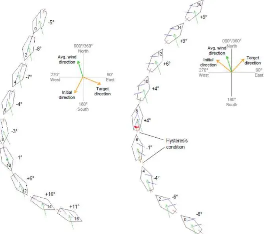
Several test runs were carried out to demonstrate the feasibility and suitability of the presented approach. The data presented on figure 2.9 refers to the final test run prior to the Microtransat competition, where wind conditions were within operation range of the demonstration vessel. The process of two maneuvers being executed are shown, one representing a turn against the wind and another in favor of the wind, respectively on the left and right. The drawings represent present vessel heading, sail position, rudder position, apparent wind direction, tilting and time lapse stated.
2. RELATED WORK 2.2. Fuzzy logic control on autonomous sailing systems
3
Supporting Concepts
This chapter introduces the reader to some of the key aspects of this dissertation, such as basic sailing theory, which is important to learn how to control the vessel. It is also important to know some basic aspects of fuzzy control theory in order to design a good controller.
3.1
Basics of Sailing
In order to design a good controller for a sailboat, it is necessary to know how to sail one properly. Also, it is important to know some essential characteristics of how the vessel is built, what is the usefulness of the most important features. Finally, basic sailing techniques are going to be viewed [Sal96]. In regard to sailing techniques, the veracity of the information was confirmed using the simulator Virtual Skipper 5, available on [Ent].
3.1.1 The vessel
The most common type of small to midsize sailboat is the sloop. The basic equipment needed for sailing is composed of one mast and two sails. The mainsail is usually a tall triangular sail mounted to the mast, with its foot along the boom, which extends towards the back from the mast. The sail in front, called the headsail or the jib, mounts on the forestay between the bow (frontal part of a ship) and the masthead, with its trailing corner controlled by the jibsheet. A general idea of these components position and sides of the ship are shown in figure 3.1.
3. SUPPORTINGCONCEPTS 3.1. Basics of Sailing
Bow
Stern
Starboard Port
Figure 3.1: Main sailboat equipment [Boa] and side terms, viewed from above.
(tightening and loosening of the sail) of both mainsail and jib. Since this is a simple setup, only these two components and the keel are going to be analyzed. The sail will be analyzed in section 3.1.2.
Keel or Centreboard
If the wind is coming from behind the stern, the ship is pushed by it, but if the wind is coming from the side it pushes the vessel sideways. To reduce this effect, a boat needs a suitable underwater surface to lessen this drift. This drift, know as leeway, cannot be completely eliminated but can be kept within reasonable limits by the surface presented. It can also prevent capsizing. This device is the ship’s keel. The two main categories of keels are swinging centreboards and daggerboards. Centreboards are a rotating type of keel that can be adjusted while sailing. Daggerboards are fixed boards inserted into a case, in the center of the vessel. The used vessel uses a daggerboard type keel.
Rudder
3. SUPPORTINGCONCEPTS 3.1. Basics of Sailing
Figure 3.2: Killer Whales Yacht.
3.1.2 The use of sails
Wind variables
The wind actually experienced on a vessel is called apparent wind. It is slightly different in strength and direction from the real (true) wind because a moving boat creates its own airflow, called the head wind. Apparent wind is a combination of head and true wind, as shown by figure 3.3.
Figure 3.3: Experienced winds [Ass].
3. SUPPORTINGCONCEPTS 3.1. Basics of Sailing
is not immediate, for a moment the head wind remains just as it was. This causes a momentarily change of direction of the apparent wind, making it come more from the side. On the other hand, if the windspeed drops suddenly the vessel’s speed will me maintained for a few seconds and, following the same logic, the apparent wind will come more from ahead. On both situations the vessel’s direction needs to be adjusted in order to prevent a loss of speed.
Sails as wind resistance
The earliest form of sailing was based on using the wind simply to push the boat along. The sail area was arranged as much at right-angles to the wind as possible. The more area available on the sail, the greater the resistance offered to the wind, thus more power was available for propulsion.
With the wind dead behind, the shape of the sail or sails is very important. The more concave or parachute like the shape of the sail the greater is the resistance offered to the wind. Yet, it is a mistake to think that a boat is sailing at its fastest downwind (with the wind dead behind). In this situation, the wind meets the sails at right-angles and eddies around behind them. This way of operation is more the exception than the rule. Most of the time the wind comes sideways and flows parallel to the curve of the sails, as such, they act as aerofoils.
Sails as aerofoils
The force of the wind can also be used to make progress against it. For this, the sail surfaces need to have an aerodynamic shape. In a cross-section view, sails resemble air-craft wings. When they are trimmed correctly the wind is deflected so delicately that the airflow remains unbroken. Lift (a combination of suction on one side and pressure on the other) is developed in the side furthest from the wind and acts at right-angles to the sail as shown in figure 3.4. Another smaller force acts parallel to the sails, caused by resistance offered to the airflow.
The force of the wind against the sails consists of two components, lift and resistance. The two can be expressed as a single force operating in between the two components, by means of a vector diagram. This force would be neither straight ahead nor at right-angles to the boat, it would act diagonally instead.
Therefore, the vessel is being pushed not only forward but also sideways. This side-ways force is counteracted to a great extent by the keel, explained in subsection 3.1.1.
3.1.3 Sailing Techniques
Running before the wind
3. SUPPORTINGCONCEPTS 3.1. Basics of Sailing
Figure 3.4: Lift and aerodynamic force created by the wind [Saib].
In modern sailing boats, this means arranging all the sails in such a way that the largest area possible is presented to the wind. For this to happen, the headsail and mainsail need to be on different sides (goosewinged) as seen on figure 3.5 a).
Broad reaching
If the wind is neither coming from the stern nor blowing at right-angles but coming from between these two, the vessel is sailing on a broad reach. Both sails are set on the farthest side from the wind (leeward) and the sheets are eased. This happens because the wind is not just striking the sails at right-angles but is also being deflected slightly by them. This makes the vessel go faster than running before the wind (figure 3.5 b)).
a) Running before the wind b) Broad reaching
Figure 3.5: Sailing techniques 1 [Sal96].
Bearing away
3. SUPPORTINGCONCEPTS 3.1. Basics of Sailing
Luffing
Luffing means altering the course towards the direction from which the wind is coming. It does not matter whether the vessel turns to port or starboard, luffing is always done when turning towards the wind. It is not simply a matter of steering, the sail sheets need to be adjusted progressively. They need to be gradually pulled in so that the vessel does not slow down, consequence of flapping sails.
If luffing is done from the stern to a beam reach (when the wind is roughly at right-angles to the vessel) the sails need to be tightened until they stop fluttering. If the wind is light the vessel should be allowed to heel so that gravity helps the sails adopt the correct angle and curvature.
If luffing is done until the vessel is close-hauled (sailing as close to the wind direction as possible without stopping, figure 3.6 b)) the sail sheets are progressively pulled in.
a) Bearing away b) Luffing
Figure 3.6: Sailing techniques 2 [Sal96].
Beating to windward
It is impossible to sail straight to the wind, instead, to beat to windward, or upwind, a zigzag route must be adopted as shown in figure 3.7 a). The aim is to sail fast without reaching too far from the objective. Short routes lead to too much loss of speed because the boat is heading too much into the wind to sail well. Also, if the boat does not point high enough into the wind the route becomes much longer than expected. A compromise between these two must be found.
It can be very difficult in practice to pick the best route to windward as windshifts also have to be taken into account.
Tacking
3. SUPPORTINGCONCEPTS 3.2. Fuzzy Control
a loss of speed and if the vessel does not have enough to carry through the turn it may not respond to the rudder and stop. The rudder should also not be turned too sharply because this too has a breaking effect. This maneuver is done at the end of each diagonal leg of a windward beating course.
Because the vessel is constantly losing speed doing this maneuver, it is important to get the wind back in the sails as quickly as possible and regain speed. Also as said before, if the rudder is turned too much it will act as a brake because the blade is at a sharp angle to the water flow. Another compromise has to be found between loss of speed and time taken to do the tacking maneuver. If the rudder is not pushed far enough, there is a long delay with constant speed dropping until the wind catches the sails again. It is generally accepted that the best rudder angle is about330to the centreline of the boat. It is specially important not to come to a full stop while tacking because a sailing boat without speed cannot be steered.
Stopping
The only way to stop a sailing boat is to turn it directly into the wind to make it start losing speed. Judgement is needed to gauge how far the vessel will travel head-to-wind until it stops. Once the goal is reached, the sail sheets are fully released and the rudder is turned hard into the direction of the wind as shown in figure 3.7 b).
b) Stopping a)
Figure 3.7: Sailing techniques 3 [Cat, Sal96].
3.2
Fuzzy Control
3.2.1 An Introduction
3. SUPPORTINGCONCEPTS 3.2. Fuzzy Control
Conventional knowledge representation techniques do not provide effective tools for representing the meaning of everyday like facts such as:
• Usuallyit takesabout an hourto drive from Berkeley to Stanford inlighttraffic.
• Mostexperts believe that the likelihood of asevereearthquake in thenearfuture is
very low.
The words in italic in the assertions are labels for fuzzy predicates, quantifiers and probabilities. Conventional approaches to knowledge representation lack the means to represent fuzzy concepts. Consequently, approaches based in first order logic and clas-sical probability theory do not provide an appropriate framework for dealing with com-monsense knowledge since such knowledge is both imprecise and noncategorical by na-ture [Zad89].
The development of fuzzy logic was motivated mainly by the need for a concep-tual framework capable of addressing the issues of uncertainty and lexical imprecision. Nowadays fuzzy logic has emerged as an alternative to classical logic in application areas ranging from industrial process control to aerospace and bioengineering [Sug85, Zim91].
3.2.2 Applications
Possibly the most impressive fact about the present success of fuzzy logic is the wide array of applications of this paradigm, ranging from consumer products to automotive engineering. Table 3.1 illustrates this point with a list of fuzzy logic uses in an industrial setting. In brief, fuzzy logic plays a similarly central role in shaping a suitable rule-based or linguistic control strategy in these applications.
Furthermore, in the majority of these cases, fuzzy logic bridges the gap between sym-bolic processing and numeric computation, thereby expanding the domain of applica-tion of control engineering to those outside its realm of usage. Specifically, fuzzy logic can form the basis of implementation of control strategies in the wide sense to include decision making and supervisory control.
Table 3.1: Applications of fuzzy logic control, as seen in [YLZ95] page 6.
Consumer Products AutomotivePower Generationand IndustrialControl Process Robotics and Manu-facturing
•Cameras and cam-corders (Canon, Mi-nolta, Ricoh, Sanyo)
•Power train and transmission control (GM-Saturn, Honda, Mazda)
•Cement kiln, inceneration plant (K.L.Smith)
•Electrical dis-charge machine (Mitsubishi)
•Washing machines (AEG, Sharp, Gold-star)
•Engine control (Nissan)
•Refining, distil-lation and other chemical processes •Refrigerators
3. SUPPORTINGCONCEPTS 3.2. Fuzzy Control
3.2.3 Essential characteristics
As the name suggests, fuzzy logic is the logic underlying modes of reasoning which are approximate, and not entirely exact. The importance of fuzzy logic comes from the fact that most modes of human reasoning are approximate in nature, such as commonsense reasoning. It is interesting to note that approximate reasoning falls outside the range of classic logic, because the main concern of the later topic is the reasoning that leads to precise formulation and analysis.
Some of the main characteristics of fuzzy logic relate to the following: • Exact reasoning is viewed as a limited case of approximate reasoning; • Everything is a matter of degree;
• Any logical system can be fuzzified;
• Inference is viewed as a process of propagation of flexible constraints;
Fuzzy logic differs from traditional logical systems in spirit and detail. Some of the main differences are summarized in the following [Zad83].
• Truth:In bivalent logical systems, truth can have two values:trueorfalse. In multi-valued systems it can be an element of a finite set, an interval or a boolean algebra equation. In fuzzy logic, truth may be a fuzzy subset of any partially ordered set or, a point in the interval[0,1]. The so-called linguistic truth values such astrue, par-tially true,not quite trueare interpreted as labels of fuzzy subsets on an unit interval.
• Predicates: In bivalent systems, predicates are crisp, likemortal,even,larger than. In fuzzy logic, predicates are fuzzy, such astall,ill,soon,much larger than. It should be noted that most predicates in natural language are fuzzy, and not crisp.
• Predicate Modifiers: In classic systems, the most widely used predicate modifier is
the negation (not). In fuzzy logic there is a variety of predicate modifiers which act as mitigators or weakeners of statements such asvery,more or less,quite,rather,
much. Such predicate modifiers play an essential role in the generation of the values
of a linguistic variable :very young,more or less young,rather young, etc [Zad73]. • Quantifiers: In classical logical systems, only two quantifiers exist, universal and
existential. Fuzzy logic admits a wide variety of fuzzy quantifiers exemplified by
few,several,usually,most,always,frequently, etc.
• Probabilities:In classical logical systems, probability is numerical or interval valued. In fuzzy logic there is also the additional option of linguistic probabilities, exempli-fied bylikely,unlikely,around 0.5,high, etc [Zad86].
3. SUPPORTINGCONCEPTS 3.2. Fuzzy Control
3.2.4 Fuzzy logic controller architecture
Different methods for developing fuzzy logic controllers have been proposed. In the de-sign of a fuzzy controller, one must identify the main control parameters and determine a term set which is at the right level of specification for describing the values of each linguistic variable. For instance, a term set including linguistic variables such as {Small, Medium, Large} may not be enough to satisfy some domains, it may be needed to have
more terms in the set, such as {Very Small, Small, Medium, Large, Very Large} [Ber92]. Figure 3.8 illustrates a basic architecture for a fuzzy logic controller. This architecture consists on four modules whose functions will be described.
Figure 3.8: Fuzzy logic controller [Alo].
Fuzzy Sets
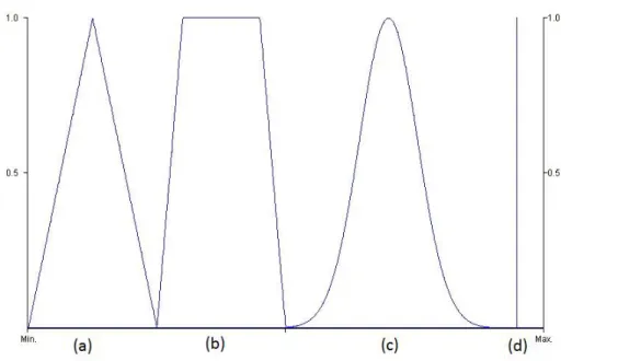
A fuzzy set is an extension of a crisp set. A fuzzy set, defined over some domain of def-inition, is a mapping from that domain into the interval[0,1]This mapping is called the membership function of a given fuzzy set. It takes the value of zero for no membership and one for full membership. In crisp sets these are the only two allowed values. Fuzzy sets also allow partial, or graded membership. In other words, an element may partially belong to a fuzzy set. Different types of fuzzy membership functions have been used to define fuzzy sets. Some of them are shown in figure 3.9 [Ber92].
3. SUPPORTINGCONCEPTS 3.2. Fuzzy Control
Figure 3.9: Different membership function types: (a) Triangular ; (b) Trapezoidal; (c) -Bell-shaped; (d) - Singleton;
membership function is described as unity at a single particular point on the universe of discourse, and zero everywhere else. The use of singletons is directly tied to the compu-tational effectiveness of a fuzzy controller.
Fuzzification strategy
In coding the values from outside the fuzzy system, one transforms the given values in terms of the linguistic variables used in the preconditions of the ruleset. If the given value is crisp, then the fuzzification stage requires matching the measurement against the membership function of the linguistic label as shown in figure 3.10. If the given value contains noise, it may be modeled using a triangular membership function where the peak of the triangle refers to the mean value of the data set and the base refers to a function of the standard deviation. The most widely used fuzzification method is the former case when the given value is crisp [Ber92].
3. SUPPORTINGCONCEPTS 3.2. Fuzzy Control
Knowledge/rule base setup
There are two important tasks in designing the knowledge/rule base setup. First, a set of linguistic variables must be properly selected in order to describe the main control parameters of the system. Both the input and output parameters must be linguistically defined using proper term sets. Also, the granularity of a term set is important for the smoothness of control. Secondly, a control knowledge base must be developed which uses the linguistic description described in the first point. Sugeno [Sug85] suggested four methods for doing this:
1. Expert’s knowledge
2. Modeling the operator’s control actions 3. Modeling a process
4. Self organization
Among these methods, the first method is the most used [MA75]. This method is effective when expert human operators can express the heuristics that they use in con-trolling a process in terms of rules.
The second method, directly models the control actions of the operator. Instead of interviewing the operator, its control actions are imitated by the system.
The third method deals with fuzzy modeling of a process where an approximate model is configured by using implications describing possible states of a system. In this method, a model is developed and a fuzzy controller is constructed to control the fuzzy model, making this approach very similar to traditional approaches in control theory.
The fourth method’s main idea is to develop rules which can be adjusted over time to improve the controller’s performance.
These rules are a collection of linguistic statements that describe how the system should make a decision regarding classification of inputs and control of outputs. Fuzzy rules are always written in the following form:
if (input1 is membership function1) and/or (input2 is membership function2) and/or ... then(outputX is output membership functionX).
Inference process
In a fuzzy ruleset, there is the possibility of more than one rule being fired at the same time, because of the partial matching attribute of fuzzy control rules and the fact that the preconditions of the rules can overlap each other. The methodology used in deciding what control action should be taken as the result of multiple rules being fired can be referred to as the process of conflict resolution, or inference.
3. SUPPORTINGCONCEPTS 3.2. Fuzzy Control
1. The strength for each rule is calculated by taking the minimum of the two input membership values (boolean "and").
2. The control output of each rule is calculated by applying the matching strength of the rule on its conclusion.
3. The control outputs of all fuzzy rules are combined to obtain one fuzzy output distribution. This output usually is obtained using a boolean "or". This technique combines the fuzzy membership functions into one.
Figure 3.11: Mamdani two input, two rule inference system [Kna].
Mamdani-type inference, as shown above, expects the output membership functions to be fuzzy sets. After the aggregation process, there is a fuzzy set for each output vari-able that will need defuzzification. It is possible and much more efficient to use a single-ton membership function than a distributed fuzzy set. Singlesingle-tons, used in Sugeno-type systems, can be thought of as pre-defuzzified fuzzy sets.
The result of this operation is a membership function and has to be defuzzified into a single crisp value in order to be used.
Defuzzification strategy
3. SUPPORTINGCONCEPTS 3.2. Fuzzy Control
suggested in literature. Among them, three of the more often applied methods are de-scribed [Ber92].
Tsukamoto’s defuzzification method calculates a crisp control action, if a monotonic membership function is used as shown in equation 3.1. This method is also known as weighted average method and is generally used in Sugeno-type inference systems. n is the number of rules with firing strength(ωi)greater than 0 andxiis the amount of control
action recommended by rulei.
Z∗ = Pn
i=1wixi
Pn i=1wi
(3.1)
The center of area method calculates the center of gravity of the distribution for the control action, assuming that it has has been produced with a point wise membership function. Assuming a discrete universe of discourse we have equation 3.2 whereqis the number of quantization levels of the output, zj is the amount of control outputs at the
quantization leveljandµC(zj)represents its membership value inC.
Z∗ = Pq
j=1zjµC(zj)
Pq
j=1µC(zj)
(3.2)
Finally, the mean of maximum method generates a crisp control action by averaging the support values which their membership values reach the maximum. For a discrete universe, it is calculated following equation 3.3 where l is the number of quantized z values which reach their maximum memberships.
Z∗ = l X
j=1 zj
4
Software and Hardware
This chapter introduces the technologies used in the elaboration of this dissertation, namely the prototyping platform, sensors and software used for model construction / system emulation.
4.1
Arduino
Arduino is an open-source electronics prototyping platform based on flexible hardware and software. Its original purpose is the development of interactive projects. The plat-form can sense the environment around it by receiving inputs from a variety of sensors and can affect its surroundings by controlling a series of actuators, such as motors. The microcontroller on the board is programmed using Wiring [BHB] based programming language and the development environment is based on Processing [FR].
There are many microcontroller platforms available for physical computing, such as Parallax Basic Stamp, Netmedia’s BX−24and MIT’s Handyboard. All of these tools are designed to transform the complicated issue of microcontroller programming into an easy to use package. Arduino also has the same functionalities but it also offers some advantages over other systems such as:
• Cost-effectiveness: Arduino boards are relatively inexpensive compared to other microcontroller platforms. The simplest versions of the Arduino module can be assembled by hand and even pre-assembled modules cost less than 20 Euros.
4. SOFTWARE ANDHARDWARE 4.1. Arduino
• Open source and extensible software: The Arduino software is published as open source tools, available for expansion by experienced programmers. The language can be expanded through C++libraries and by adding AVR-C code directly into Arduino programs.
• Open source and extensible hardware: Arduino is based on ATMEGA microcon-troller family. The plans for the modules are published under a special license that enables experienced designers to make their own versions of the module, extending and further improving it.
4.1.1 Hardware
The Arduino board used for this project is an Arduino Mega 2560 [Ban] as shown in picture 4.1.
Figure 4.1: Arduino Mega 2560 board [Ban].
This is a microcontroller board based on the ATmega2560 [Cor12] with characteristics such as 4 hardware serial ports, USB connection, reset button, ICSP (In Circuit Serial Programming) header and others. The main characteristics of this board are listed in table 4.1.
In terms of power supply, Arduino Mega can be powered via USB connection or with an external power supply. The source is selected automatically. With an external supply the board can operate on the 6−20volt range. However, less than 7V supply can turn the board unstable and more than 12V may damage the board, as such the recommended range of operation is 7 to 12 volt.
The 54 digital pins can be used as inputs or outputs, in addition, some pins have specialized functions:
• Serial 0: 0(RX), 1(TX); Serial 1: 19(RX), 18(TX); Serial 2: 17(RX), 16(TX); Serial 3: 15(RX) and 14(TX). Used to receive (RX) and transmit (TX) TTL serial data.
4. SOFTWARE ANDHARDWARE 4.2. Proposed sensors for the project
Table 4.1: Arduino Mega 2560 features.
Microcontroller ATmega2560
Operating Voltage 5V
Input Voltage (recommended) 7-12V
Input Voltage (limits) 6-20V
Digital I/O Pins 54 (of which 15 provide PWM output)
Analog Input Pins 16
DC Current per I/O Pin 40 mA
DC Current for 3.3V Pin 50 mA
Flash Memory 256 KB of which 8 KB used by bootloader
SRAM 8 KB
EEPROM 4 KB
Clock Speed 16 MHz
19 (interrupt 4), 18 (interrupt 5). These pins can be configured to trigger an interrupt on a low value, rising edge, falling edge or a change in value.
• PWM: 2–13 ; 44–46. Provides 8-bit PWM output.
• LED: 13. There is a built-in LED connected to digital pin 13 which is ON if the pin is HIGH value and OFF when the pin is LOW.
• SPI: SPI: 50 (MISO), 51 (MOSI), 52 (SCK), 53 (SS). These pins support SPI (Serial Pe-ripheral Interface) using a library created for the effect. These pins are also broken out on the ICSP header, which is physically compatible with other Arduino boards. • TWI: 20 (SDA) and 21 (SCL). Supports TWI(Two-wire interface) using a library
cre-ated for the effect.
The 16 analog inputs provide 10 bits of resolution (1024 different values). By default they measure from ground to 5 volts though it is possible to change the upper end of their range.
4.2
Proposed sensors for the project
The initial set of sensors included a wind vane (to measure wind direction), anemometer (to measure wind speed), compass (to know the vessel’s heading and inclination) and GPS (to obtain the vessel’s position and speed). The proposed models are shown in this section.
4.2.1 Weather meter
4. SOFTWARE ANDHARDWARE 4.2. Proposed sensors for the project
None of the sensors in this kit contain active electronics, instead they use sealed mag-netic switches and magnets . The cup anemometer encodes the wind speed by closing a switch with each rotation, A windspeed of 1,492 Miles per Hour produces a switch clo-sure once per second. The wind vane reports wind direction as a voltage produced by a combination of resistors inside the sensor. When a voltage is supplied, the return can be translated to any of 16 possible positions. The users manual has a table of voltage and resistance values for each of the 16 positions [Sysa].
4.2.2 CMPS10 Tilt Compensated Magnetic Compass
The CMPS10 module shown in figure 4.2 b) is a tilt compensated compass employing a 3-axis magnetometer and a 3-axis accelerometer and a 16-bit processor, it has been de-signed to remove the errors caused by tilting of the PCB (Printed Circuit Board). The CMPS10 produces a result of 0-3599 representing 0-359.9 or 0 to 255. The output of the three sensors measuring x, y and z components of the magnetic field, together with the pitch and roll are used to calculate the bearing, each of these components are also made individually available [PTRb].
The module requires a power supply at 3.3 - 5v and draws a nominal 25mA of current. There are three ways of getting the bearing from the module: A serial interface, an I2C interface or a PWM output. More information about this sensor is available in [Ele].
4.2.3 EM-406A SiRF III GPS Receiver with Antenna
The EM-406A GPS module shown in figure 4.2 c) includes on-board voltage regulation, LED status indicator, battery backed RAM, and a built-in patch antenna. Its main features are a 20 channel receiver, high sensitivity (-159dBm) and 10m positional accuracy [PTRa]. This module requires a power supply of 4.5 - 5.5v and draws a nominal 70mA of current. It has an average cold starting time of 42 seconds and an average 1 second of hot start. For more information on this sensor check [Glo].
It is also important to note the protocol used by GPS sensors, the NMEA (National Marine Electronics Association) protocol [Sta]. This protocol defines the interface be-tween various pieces of marine electronic equipment and permits information sending from marine equipment to computers and vice versa. Standard GPS receiver communi-cation is defined on the NMEA specificommuni-cation.
The idea of NMEA is to send a line of data (an NMEA sentence) that is independent from other NMEA sentences. There are standard sentences for each device category and the ability to define proprietary sentences. All standard sentences have a two letter prefix that identifies the device using the sentences (for GPS receivers the prefix is GP) followed by a three letter sequence that defines the sentence contents. Standard sentences are constructed using the following rules:
4. SOFTWARE ANDHARDWARE 4.2. Proposed sensors for the project
• The following five characters indicate the origin and type of message as explained.
• Different data items in the sentence are separated by commas.
• If no data is available in an item it is sent null, for example "..123„456...".
• The last item is a checksum field, consisting of a ’*’ character and two hexadecimal digits representing an 8 bit exclusive OR of all characters between ’$’ and ’*’. This checksum is obligatory on some sentences only.
The sentence used in this dissertation is the RMC (Recommended minimum data for GPS). This sentence has all the data needed for the controller’s specification as it will be explained later. RMC data format is shown in table 4.2.
Table 4.2: RMC Data Format, adapted from [ST].
Name Example Units Description
Message ID $GPRMC RMC protocol header
UTC time 161229.487 hhmmss.sss
Status A A=data valid or V=data not valid
Latitude 3723.2475 ddmm.mmmm
N/S Indicator N N=north or S=south
Longitude 12158.3416 dddmm.mmmm
E/W Indicator W E=east or W=west
Speed Over Ground 0.13 knots
Course Over Ground 309.62 degrees True
Date 120598 ddmmyy
Magnetic Variation 003.1 degrees E=east or W=west
Mode A A=Autonomous, D=DGPS, E=DR
Checksum *10
<CR> <LF> End of message termination
a) b) c)
4. SOFTWARE ANDHARDWARE 4.3. Available sensors and emulators
4.3
Available sensors and emulators
While the proposed sensors were unavailable, progress was mostly done using emulators and software to artificially recreate and simulate the needed environment. Using the same type of interfaces between the sensors and the Arduino prototyping board it is possible to test the behavior of developed algorithms. In order to achieve this, a kit using a PIC18F4550 microcontroller was developed [Gil13]. This emulator receives instructions via USB from a computer through a simulation platform and implements the original interface communication (original protocols used where UART [Mica] and SSI [NI]) from each sensor to the Arduino. To complete the cycle, Arduino implements the PWM signals needed to move the rudder and sail servomotors just as shown in figure 4.3. All the work presented in this section can be consulted in [Gil13].
Figure 4.3: Sensorial emulation setup [Gil13].
4.3.1 Simulation platform
In order to obtain and easy to use interface a simulator was developed in MATLAB. The user simply has to fill forms and send information to the available emulators. This simulator operates on two different modes:
• Step-by-Step mode • Automatic mode
On Step-by-Step mode, the user fills a form with the information he/she wants to send, referent to each sensor. Clicking a send button, the respective data is sent by USB to the PIC18F4550 through a virtual COM interface [Micb]. Each sensor is individually identified by the characteristics of the protocol it uses and the types of data sent.
4. SOFTWARE ANDHARDWARE 4.4. Xfuzzy
Step-by-Step mode
Automatic mode
Figure 4.4: Simulation interface, adapted from [Gil13].
4.3.2 PIC-Arduino interface
The emulator created using a PIC18F4550 microcontroller in order to emulate sensorial data uses two different types of interfaces with the system: two UART interfaces and one SSI. Data receiving uses an USB connection from the computer, the sensor array use UART for the GPS and compass modules, and SSI for the wind direction sensor (origi-nally, an AS5040 [Aus] sensor was going to be used for wind direction calculation).
The main algorithm implemented on this microcontroller behaves as a regulator that routes messages received via USB to their respective destinations. Message association is made through the first two characters present on the string message. If the first character is not ’$’ then the message is relative to the AS5040 sensor. If the first character is ’$’ then the message is relative to the GPS or compass modules, which are distinguished by the second character being ’G’ or ’C’, respectively. Besides data reception and transmission, the PIC18F4550 implements an interrupt routine capable of replying to the Arduino’s solicitations.
4.4
Xfuzzy
4. SOFTWARE ANDHARDWARE 4.4. Xfuzzy
The version used in the aiding of this project was Xfuzzy 3 [dMdSc]. Its main fea-tures are the capability for developing complex systems and the flexibility of allowing the user to extend the set of available functions. The environment has been completely programmed in Java, so it can be executed on any platform with JRE (Java Runtime En-vironment) installed. The design flow of Xfuzzy 3 includes the following stages:
1. Description stage - This stage includes graphical tools for the fuzzy system defini-tion and development. This definidefini-tion of the system is made using the xfedit tool [dMdSd]. This tool defines the linguistic variables, logical relations between them, operator sets and rule bases of the created system.
2. Verification stage - This stage includes tools for simulation, monitoring and repre-senting graphically the system behavior. The aim is to detect possible deviations on the expected behavior and to identify the deviation sources. From the tools avail-able for verification, the simplest to use is the xfmt tool [dMdSb]. This monitoring tool shows the activation degree of every linguistic label and logical rule, as well as the value of the different input variables, for a given set of input values.
3. Tuning stage - This stage consists in applying identification, learning and simpli-fication algorithms to the fuzzy system. It is usually one of the most complex tasks when designing a fuzzy system. The system behavior depends on the logic structure of its rule base and the membership functions of its linguistic variables. The tuning process if often focused on adjusting membership function parame-ters. Manually this process is cumbersome, automatic techniques are preferable. The two most widely used learning mechanism and supervised and reinforcement learning. Xfuzzy 3 currently contains one tool dedicated to supervised learning algorithms. The tuning stage was not reached in this dissertation.
5
Proposed controller
This chapter will introduce all the work developed for this dissertation. Caused by the lack of sensors some methods could not be tested. Section 5.1 introduces a method for au-tomatic control transition and the sections after explain the design used for the controller. The final design can be viewed in figure 5.1. Most of the protocols used and routines for data treatment are explained in detail in [Gil13].
GPS
Compass
Wind vane
Anemometer
Rudder
Sail Rudder control
Sail control Controller
Fuzzy Variables:
• Directional
alignment
• Boat speed
• Wind
alignment
• Wind
speed
• Roll
Favorable wind
Tack right
Tack left
Sail SSI
PWM SSI
PWM
UART
Not
Known
Yet
Sensors used for data input Control Structure Servomotors controlled by output implemented
Protocols Protocols
5. PROPOSED CONTROLLER 5.1. Transition between manual and automatic control
5.1
Transition between manual and automatic control
Since a prototype of an automatic system is prone to failure, it is always good practice to add safety failsafe methods. On the prototype vessel used there is the possibility of using the original manual remote controller to add this specification. The objective is to give manual control to the user as soon as the remote controller is on, if the controller is off then the remote system controls the vessel.
The Killer Whales Yacht comes equipped with a Radio Frequency module for com-municating with the remote controller. The signal generated from this module is different whether the remote controller is on or off, as shown in figures 5.2 and 5.3.
Figure 5.2: Signal generated when the remote controller is off.
Figure 5.3: Signal generated when the remote controller is on (noise is irrelevant in this case as it is only generated from the RF waves into the oscilloscope).
5. PROPOSED CONTROLLER 5.1. Transition between manual and automatic control
?
MUX
Figure 5.4: Transition between manual and remote control.
There is still the need to know how to select the right input to control the sailboat. To solve this problem, the PWM values associated with the rudder and sail servo-motors generated in the RF Module were used. Figure 5.5 shows two random signals with the controller off and one stable signal with the controller on.
Controller off Controller on
Figure 5.5: Different characteristics in the controller’s signal.
After analysis it is easily seen that with the controller on, the RF module signal is a PWM pulse of±23msand with the controller off this signal becomes a series of random pulses. Also, the total period of the positive signal (5V) is less when the controller is off. Using this property it is possible to distinguish the two types of signal through the method described in figure 5.6.
5. PROPOSED CONTROLLER 5.1. Transition between manual and automatic control
Verify signal
1 0
Increment counter in X
units
Decrement counter in Y
units
Wait Z ms 0 or 1?
Verify counter value Lower threshold Upper threshold Activate automatic control Activate manual control Keep same control strategy No
Does it go over a threshold?
a) b)
Figure 5.6: a)Counter implementation flowchart; b)Transition strategy flowchart;
Limiting the counter’s upper and lower values (between 0 and 512) opens the pos-sibility of stabilization. This way, and testing different values forX,YandZtable 5.1 is
obtained. Since the data obtained when the controller is off and on differs, thresholds can be established to signalize the right moment for changing the control strategy (5.6 b). To prevent unwanted rapid switching between strategies more than one threshold is established, making this process acquire an hysteresis effect.
Table 5.1: Test results for acquiring efficient threshold values.
Parameters Maximum counter value
Sampling Period (Z) Increment (X) Decrement (Y) Controller: off Controller: on 0.2 ms
10 1 272 70
20 1 366 531
30 2 540 540
0.33 ms
30 1 387 531
40 2 532 156
60 3 550 560
0.5 ms
20 1 313 541
30 2 430 550
50 2 558 570
![Figure 2.1: FEUP Autonomous Sailboat [AC09].](https://thumb-eu.123doks.com/thumbv2/123dok_br/16570593.737992/28.892.144.709.305.668/figure-feup-autonomous-sailboat-ac.webp)
![Figure 2.2: FASt’s electronic system, adapted from [AC09].](https://thumb-eu.123doks.com/thumbv2/123dok_br/16570593.737992/29.892.114.813.299.714/figure-fast-s-electronic-system-adapted-from-ac.webp)

![Figure 3.1: Main sailboat equipment [Boa] and side terms, viewed from above.](https://thumb-eu.123doks.com/thumbv2/123dok_br/16570593.737992/38.892.143.707.125.557/figure-main-sailboat-equipment-boa-terms-viewed.webp)
![Table 3.1: Applications of fuzzy logic control, as seen in [YLZ95] page 6.](https://thumb-eu.123doks.com/thumbv2/123dok_br/16570593.737992/44.892.109.782.872.1125/table-applications-fuzzy-logic-control-seen-ylz-page.webp)

![Figure 3.11: Mamdani two input, two rule inference system [Kna].](https://thumb-eu.123doks.com/thumbv2/123dok_br/16570593.737992/49.892.131.805.358.809/figure-mamdani-two-input-rule-inference-system-kna.webp)
![Figure 4.4: Simulation interface, adapted from [Gil13].](https://thumb-eu.123doks.com/thumbv2/123dok_br/16570593.737992/57.892.215.719.113.477/figure-simulation-interface-adapted-from-gil.webp)
