A Qualification Methodology for Additively Manufactured
Parts
University of Maryland, Baltimore County
João Carlos do Carmo Santos
Dissertação de Mestrado
Orientador na UMBC: Dr. Marc Zupan Orientador na FEUP: Dr. Abel Dias dos Santos
Mestrado Integrado em Engenharia Mecânica
Resumo
A tecnologia de Fabrico Aditivo tem o potencial de revolucionar a forma como as empresas produzem quase tudo. Este processo de fabrico inovador foi recentemente implementado pela Marinha dos Estados Unidos na forma de projetar, fabricar, armazenar e entregar componentes. O processo de sinterização direta por laser de metais (DMLS do inglês Direct Metal Laser Sintering) é um novo sistema capaz de produzir componentes de grande porte ou estruturas complexas próximas da forma final através da tecnologia de fabrico aditivo de forma totalmente automática, sem necessidade de ferramentas e diretamente baseado num modelo CAD. As ligas de titânio são particularmente utilizadas na produção de componentes em motores aeronáuticos, conjugando boas caraterísticas mecânicas específicas e uma excelente resistência à corrosão a altas temperaturas.
Neste trabalho de investigação foi apresentado um novo método para caracterizar peças produzidas por fabrico aditivo. Uma chapa com 1mm de espessura produzida por DMLS na liga de titânio Ti6Al4V (ou Ti64) foi submetida à técnica de teste com microprovetes, técnica esta capaz de fornecer informações que de outra forma seriam escondidas ou até mesmo impossíveis de obter à macro escala. Esta metodologia abrange a determinação da tensão limite de elasticidade, resistência à tração máxima, alongamento e módulo de Young, assim como a microestrutura e superfícies de fratura são também analisadas.
O comportamento mecânico local foi analisado em duas direções. Os resultados corroboram o cenário de uma terceira revolução industrial, sendo que foi observado um aumento na resistência em relação aos processos de fabrico tradicionais. Além disso, verificou-se que as propriedades dependiam da orientação dos provetes, o que comprovou a anisotropia característica de componentes produzidos por fabrico aditivo e, assim, atestou a capacidade da metodologia proposta de fornecer dados fiáveis para modelos globais de desempenho de componentes estruturais.
Abstract
Additive Manufacturing (AM) has the potential to revolutionize the way companies produce almost everything. As an exciting new technology, AM has recently come on the scene on how Navy designs, manufactures, stores, and delivers parts to the warfighter. Direct Metal Laser Sintering (DMLS) is an innovative system that explores the near-net shaping of large components and net shaping of small complex structures by means of AM - fully automatically, without tools and based directly on three-dimensional CAD design data. Titanium alloys provide high strength-to-weight ratio and good creep resistance at high temperatures, which makes them a natural fit to produce components in aero-engines.
This research discusses a new technique to qualify additively manufactured parts. A DMLS produced plate of 1 mm thick in Ti6Al4V (or Ti64) was subjected to microsample mechanical testing technique, which provides information that would otherwise be averaged or masked on the macroscale. It encompasses the determination of yield strength, ultimate tensile strength, elongation, and young’s modulus. The microstructure and fracture surfaces were characterized as well.
The local mechanical behavior was described in two different directions. The results have corroborated the scenario of a third industrial revolution, where an increase in strength over traditionally manufactured components was observed. Additionally, the orientation-dependent properties proved anisotropic behavior for AM parts and thus attested the aptitude of microscale testing to provide verifiable property data as inputs to global part performance and failure models.
Acknowledgements
I would like to first thank Dr. Marc Zupan for giving me the opportunity to work under his advisement in the Micro Materials Characterization Lab and allowing me to work on par with his other graduate students. He has also played a very important part in helping me set up when I arrived to UMBC, along with my colleagues from the Global Engineering course. Without them I would not have enjoyed this experience as much as I did. This exchange would also not have been possible without the help of Dr. Abel Santos, to whom I am grateful for lending his assistance throughout the entire process.
I want to thank my two friends and lab mates Michael Duffy and Salahudin Nimer for their tuition, good conversations, and suggestions. It was a pleasure going through this entire process of thesis writing with them and I could not be more thankful to for their help. Without their know-how and advice I could not have finish this thesis workout. I would also like to thank my friends and colleagues from FEUP who accompanied me during these last five years in this pursue of the Master’s degree in Mechanical Engineering, and it was a pleasure going through it with them.
This work was funded through the Office of Naval Research. This thesis was a collaborative effort with the Naval Air Station Patuxent River and I want to thank the organization for providing the material.
I would like to finally and most importantly thank my parents Joaquim Santos and Laura Carmo for their support and advice throughout my academic career. They taught me the most valuable lessons in life in that hard work and persistence lead to success.
Table of Contents
ABSTRACT ... II ACKNOWLEDGEMENTS ... III TABLE OF CONTENTS ... IV LIST OF ACRONYMS ... VII LIST OF FIGURES ... IX LIST OF TABLES ... XII
1 INTRODUCTION ... 1
1.1 INTRODUCTION ... 1
1.2 MOTIVATION ... 1
1.3 AIMS AND SCOPE ... 1
1.4 THESIS OVERVIEW ... 2
2 LITERATURE REVIEW ... 4
2.1 ADDITIVE MANUFACTURING (AM) ... 4
2.1.1 Introduction ... 4
2.1.2 Working Principle of Additive Manufacturing ... 4
2.1.3 Additive Manufacturing Processes ... 5
2.1.4 Materials... 7
2.1.5 Applications ... 8
2.1.5.1 Aerospace...8
2.1.5.2 Automotive ...9
2.1.5.3 Biomedical ...10
2.2 METAL ADDITIVE MANUFACTURING ... 11
2.2.1 Introduction ... 11
2.2.2 Metal Additive Manufacturing Systems ... 11
2.2.2.1 Powder Bed Fusion Systems...12
2.2.2.2 Powder Feed Systems ...14
2.2.2.3 Wire Feed Systems ...15
2.2.3 Evaluation of the Metal Additive Manufacturing Processes ... 16
2.2.3.1 Quality ...16
2.2.3.2 Time ...17
2.2.3.3 Cost ...17
2.2.3.4 Environmental Impact ...18
2.2.4.1 Feature Size, Surface Finish and Geometry Scaling ...19
2.2.4.2 Build Chamber Atmosphere ...21
2.2.4.3 Feedstock quality ...21
2.2.4.4 Beam-powder Interactions ...23
2.2.4.5 Porosity ...24
2.2.4.6 Scan Strategy ...25
2.2.4.7 Deposition Strategy ...26
2.2.4.8 Cracking, Delamination and Swelling ...26
2.2.4.9 Substrate Adherence and Warping ...28
2.2.4.10 Residual Stress ...29
2.2.5 Post-processing ... 29
2.2.5.1 Powder, Support and Substrate Removal ...29
2.2.5.2 Thermal Post-processing ...30 2.2.5.3 Surface Finishing ...32 2.3 ADDITIVE MANUFACTURING OF TI6AL4V ... 33 2.3.1 Introduction ... 33 2.3.2 Titanium Ti6Al4V ... 35 2.3.2.1 Phase Diagram ...36
2.3.2.2 Development of Microstructure during Continuous Cooling ...37
2.3.2.3 Microstructure and Mechanical Properties ...39
2.3.3 Published Mechanical Properties of Additively Manufactured Ti6Al4V ... 40
2.3.4 Gaps and Future Research Needs ... 48
3 METHODS AND MATERIALS ...50
3.1 INTRODUCTION ... 50
3.2 ADDITIVELY MANUFACTURED TI6AL4V ... 50
3.3 MICROSAMPLE MECHANICAL TESTING TECHNIQUE ... 51
3.3.1 Microsample Preparation ... 52
3.3.2 Microsample Testing System Design ... 54
3.3.3 Strain Measurement ... 56
3.4 DIGITAL IMAGE CORRELATION (DIC) ... 56
4 RESULTS AND DISCUSSION ...58
4.1 INTRODUCTION ... 58
4.2 MICROSTRUCTURE CHARACTERIZATION ... 58
4.3 MICROSAMPLE TENSILE TEST RESULTS ... 59
4.4 FRACTOGRAPHY ... 64
4.5 DISCUSSION OF MICROSTRUCTURE, TENSILE PROPERTIES AND FRACTURE SURFACES CORRELATION ... 65
5 CONCLUDING REMARKS ...72
5.1 INTRODUCTION ... 72
5.3 EXPERIMENTAL TESTING ... 73
5.4 FUTURE DEVELOPMENT AND RESEARCH ... 75
REFERENCES ...78
APPENDIX A: MICROSTRUCTURES ...91
APPENDIX B: FRACTURE SURFACES ...98
List of Acronyms
3D – Three-Dimensional3DP – Three-Dimensional Printing AM – Additive Manufacturing
ASTM – American Society for Testing and Materials bcc – body-centered cubic
CAD – Computer Aided Design CNC – Computer Numeric Control DED – Direct Energy Deposition DIC – Digital Image Correlation DMD – Direct Metal Deposition DMLM – Direct Metal Laser Melting DMLS – Direct Metal Laser Sintering
EBAM – Electron Beam Additive Manufacturing EBM – Electron Beam Melting
EDS – Electron Dispersive Spectroscopy FDM – Fused Metal Deposition
GA – Gas Atomization
hcp – hexagonal closed-packed HC – Hexagonal Crystal HCF – High Cycle Fatigue HIP – Hot Isostatic Pressing
LMD/LENS – Laser Metal Deposition LOM – Laminated Object Manufacturing MJM – Material Jetting Modeling
OM – Optical Metallographic PA – Plasma Atomization
PREP – Plasma Rotating Electrode Process RA – Rotary Atomization
RX – Recrystallization
SEM – Scanning Electron Microscopy SLA – Stereolithography
SLM – Selective Laser Melting SLS – Selective Laser Sintering S.O. – Specimen Orientation ST – Solution Treat
STL – Standard Tessellation Language UTS – Ultimate Tensile Strength
List of Figures
Figure 1 – Overall view of the proposed qualification methodology for additively manufactured parts. . 2
Figure 2 – Generalized AM process [9]. ... 5
Figure 3 – Schematic visualization of AM field and research and development opportunities [12]. ... 8
Figure 4 – (a) Turbine blade with internal cooling channels produced by SLM (Source: Concept Laser [18]); (b) Hollow static blade casting using the mold and cores fabricated by 3DP (Source: ExOne [19]); (c) Damaged blisk repaired using LENS (Source: Optomec [20]). ... 9
Figure 5 – Illustrative applications of AM in a motorsport vehicle [21]. ... 10
Figure 6 – Schematic overview of the SLM process [31]. ... 13
Figure 7 – Generic illustration of an AM powder feed system [27]. ... 15
Figure 8 – Schematic view of an AM wire feed system [27]. ... 15
Figure 9 – Overview of relationship between input parameters and underlying physics to meet to expected outcome of metal AM [24]. ... 19
Figure 10 – Illustration of the layering effect, also known as stair-stepping effect, of a layer-based AM process [42]. ... 20
Figure 11 - Comparison of powder quality: (a) SEM 250× of GA, (b) SEM 500× of GA, (c) LOM of GA, (d) SEM 200× of RA, (e) SEM 500×of RA, (f) LOM of RA, (g) SEM 200× of PREP, (h) SEM 500× of PREP, (i) LOM of PREP [45]. ... 22
Figure 12 - Scan strategies used to determine heat source path in metal AM as seen in the X-Y plane (perpendicular to the build direction): (a) unidirectional or concurrent fill; (b) bi-directional, snaking, or countercurrent fill; (c) island scanning; (d) spot melting; (e) spot melting contours with snaking fill; and (f) line melting contours with snaking fill [24]. ... 26
Figure 13 – Delamination (a) and melt ball formation (b) in EBM stainless steel [65]; Slightly deformed overhang in EBM Ti6Al4V [24]. ... 28
Figure 14 – Schematic of build plate warping effect during processing (a-c) and resultant damage [66]. ... 29
Figure 15 – Post-HIP effects on metal AM parts: (a) Ti6Al4V bracket before (top) and after (down) machining [88]; (b) Thin-wall EBM fracture surface of Inconel 718 from post-HIP sample with notable change in surface oxidation and oxidation of an open pore caused by lack-of-fusion near the edge [24]. ... 32
Figure 16 – Titanium crystal structures; (a) hexagonal close-packed (hcp), α phase; (b) body-centered cubic (bcc), β phase. Adapted from [89]. ... 35
Figure 17 – Effect of alloying elements on phase diagrams of titanium alloys (schematically) [89]. .... 35
Figure 19 – Partial Ti-6Al-V phase diagram showing the Ti6Al4V composition line. Adapted from [94].
... 37
Figure 20 – CCT diagram for Ti6Al4V [91]. ... 38
Figure 21 – Types of microstructures obtained from continuous cooling of Ti6Al4V: (a) “Acicular” martensitic microstructure; (b) Lamellar α+β microstructure (Source [89]); (c) Widmanstätten or “basket weave” microstructure (Source [91]). ... 38
Figure 22 – Regimes of absorbed power and beam velocity in metal AM processes [96]. ... 40
Figure 23 – Orientation for AM coordinate system and test methodology [97]. ... 41
Figure 24 – Tensile strength, yield strength and elongation of Ti6Al4V alloy built using various metal AM processes and comparison with traditional manufacturing processes [100]. ... 42
Figure 25 - Optical micrographs of SLM-produced Ti64 samples: (a) Longitudinal cross-section showing columnar grains; (b) High magnification longitudinal cross-section image showing fine martensitic laths [from the boxed region in (a)]; (c) Transverse cross-section showing bundles of columnar grains. (d) High magnification transverse cross-section image showing fine martensitic laths in a columnar grain [from the boxed region in (c)] [118]. ... 47
Figure 26 - Optical micrograph of EBM-produced Ti64 samples: (a) Transverse cross-section; (b) Longitudinal cross-section [118]. ... 47
Figure 27 - Optical micrograph of wrought Ti64 (annealed and rolled): (a) Transverse cross-section; (b) Longitudinal cross-section [118]. ... 48
Figure 28 – Range of mechanical properties generated for structural materials; the specific properties are designed for a specific application [154]. ... 49
Figure 29 - AM technology gaps and Research and Development opportunities identified by the NSWCCD-61 organization [155]. ... 49
Figure 30 – EOS M280 system [156]. ... 50
Figure 31 – Microsample geometry (units in mm) [167]. ... 52
Figure 32 – Top: Wire EDM extracting samples; Bottom: samples extracted from AM Ti64 plate. ... 53
Figure 33 – Schematic of microsample’s location cut from AM Ti6Al4V sample. ... 54
Figure 34 – Elevated temperature microsample testing system; (a) camera, lens and light source used for DIC measurement; (b) and (c) heating system and load frame [167]. ... 55
Figure 35 – Produced speckle pattern for DIC analysis. ... 56
Figure 36 – Optical metallographic views for DMLS Ti6Al4V showing coarse, plate-like (acicular) α with some intergranular β (microsample #5 for direction d1). ... 58
Figure 37 – Stress vs. Strain Curves for direction d1 (left) and direction d2 (right). ... 60
Figure 38 – Ultimate Tensile and Yield Strength values from directions d1 and d2 microsample testing. ... 61
Figure 39 – Ultimate Tensile Strength vs. Distance from edge for directions d1 (left) and d2 (right). .. 61 Figure 40 – SEM images showing microsample fracture surface features for DMLS Ti6Al4V (microsample #5 for direction d1). ... 64 Figure 41 – SEM view for microsample #5 direction d1. ... 66 Figure 42 – Optical metallographic view from microsample #5 direction d1; (a) before testing; (b) after testing; (c) superimposition of (a) and (b) images. ... 67 Figure 43 – SEM views showing potential sources for the lowest UST value of microsample #10 direction d2. ... 68 Figure 44 - Optical metallographic view from microsample #10 direction d2; (a) before testing; (b) after testing; (c) superimposition of (a) and (b) images. ... 69 Figure 45 – SEM view of the fracture surface from the other half of microsample #10 direction d2 showing a potential source for the lowest UTS. ... 69 Figure 46 - Optical metallographic view from microsample #10 direction d1; (a) before testing; (b) after testing; (c) superimposition of (a) and (b) images. ... 70 Figure 47 - SEM top view of the fracture surface of microsample #10 direction d1. ... 71 Figure 48 - SEM top views of the matching fracture surfaces of microsample #10 direction d1. ... 71 Figure 49 - SEM view of the fracture surface from microsample #4 direction d2 showing a potential source for the lowest elongation to failure. ... 71 Figure 50 – Ultimate Tensile Strength vs. Distance from edge for directions d1 and d2, with respective linear regression curves. ... 76 Figure 51 – Voids investigation in the DMLS Ti6Al4V plate. ... 77
List of Tables
Table 1 – AM processes and equipments manufacturers [3]. ... 6
Table 2 – Materials and corresponding AM processes [2]. ... 7
Table 3 – Metal AM equipment sources and specifications. Adapted from [27]. ... 12
Table 4 – Specifications of metal AM processes. Adapted from [25]... 16
Table 5 – Typical layer thicknesses and minimum feature sizes of metal AM processes. Adapted from [24]. ... 20
Table 6 – Typical feedstock dimensions for metal AM processes. Data from [49-51]. ... 23
Table 7 – Common post-processing procedures for Ti6Al4V and Inconel 718 [24]. ... 30
Table 8 – Some important characteristics of titanium compared to other structural metals [89]. ... 33
Table 9 – Chemical Composition of Ti6Al4V alloy [93]. ... 36
Table 10 – Start and end temperature of α+β→β phase transformation for Ti6AL4V (vc = vh = 0.08°C/s). Adapted from [91]. ... 37
Table 11 – Phase composition and microstructure of T6Al4V after controlled cooling from the β phase range. Adapted from [91]. ... 38
Table 12 – Qualitative correlation between important microstructural features and mechanical properties. Adapted from [89]. ... 39
Table 13 – Summary of EBM AM Ti6Al4V tensile properties. ... 43
Table 14 - Summary of laser-based powder bed systems AM Ti6Al4V tensile properties. ... 44
Table 15 – Summary of DED AM Ti6Al4V tensile properties. ... 45
Table 16 – EOS M280 system data [156]. ... 51
Table 17 – LTA-HL Newport actuator specifications. ... 56
Table 18 – DIC analysis settings. ... 57
Table 19 – Results of microsample tensile testing. ... 60
Table 20 – Results from t-test: two samples assuming equal variances with UTS values. ... 62
Table 21 – Comparison of the results obtained from microsample testing with the published values for other laser-based powder bed systems AM Ti6Al4V. ... 63
Table 22 – Comparison of tensile strength, yield strength and elongation of DMLS Ti6Al4V with traditional manufacturing processes. ... 63
1 Introduction
1.1 Introduction
The present dissertation was developed and submitted to the Faculdade de Engenharia da Universidade do Porto (FEUP) in partial fulfillment of the requirements for the degree of Master of Science in Mechanical Engineering. The research project was developed in the University of Maryland Baltimore County (UMBC) in collaboration with the Naval Air Station Patuxent River (NAS Pax River). In this collaboration, UMBC conducted all micro-scale mechanical testing and NAS Pax River selected and procured all AM parts and performed all macro-scale mechanical testing. This collaboration links emerging AM efforts at NAS Pax River with the unique microtensile material characterization capabilities of UMBC.
1.2 Motivation
Additive manufacturing (AM) has the potential to revolutionize the way the Navy designs, manufactures, stores, and delivers parts to the warfighter. However, to realize this potential, each of these AM parts must demonstrate a set of minimum performance characteristics. These characteristics are generally assured by qualifying manufacturing processes and certifying said processes were followed by competent operators.
AM is a disruptive technology in that the Navy’s normal qualifying methodologies do not appear to readily adapt or apply. Alternatively, many groups are developing sophisticated computer models to predict mechanical performance from synthetic microstructures calculated from various AM processing parameters. While this is an elegant approach, which would represent a triumph for basic materials research, the time and cost to develop the computational infrastructure is likely long and large, and these models will require some form of validation.
1.3 Aims and Scope
The aim of the present work is to understand the reliability of the results provided by an alternative approach to evaluate AM produced structural components on Ti6Al4V. The proposed methodology, outlined in Figure 1, uses local mechanical properties derived from UMBC MicroTensile testing. The micro-tensile measurements will include the effects of microstructure and the measured local mechanical properties will substitute the outputs of intermediate microstructural models, thus providing verifiable property data as inputs to global
part performance and failure models. This is a challenging objective because, although there is a lot of published data on the mechanical properties of additively manufactured metallic materials, especially on Ti6Al4V, there is no reported work performed in a microscale.
Figure 1 – Overall view of the proposed qualification methodology for additively manufactured parts.
The scope of this research drive is to report the material performance of additively manufactured Ti6Al4V. Microstructure and mechanical properties will be obtained using UMBC MicroTensile testing technique and a comparison with the macro-scale mechanical testing results performed by NAS Pax River and published values currently available will be made. This work represents the first step in the development of a new qualification methodology for additively manufactured parts which, in the future, will be used to generate a library of basis processes-microstructures-mechanical properties for future modelers to test and verify computational models.
1.4 Thesis Overview
Chapter 2 consists in a detailed review of relevant studies important to frame this work. In the review, a brief introduction to the Additive Manufacturing (AM) process will be made, including working principle, techniques, materials, and applications. Afterwards, a more detailed review on Metal Additive Manufacturing will be made, in which the different systems will be mentioned, along with material processing issues associated with them and post-processing operations. To better contextualize this work, the published data on Additive
Manufacturing of Ti6Al4V will be presented; it will also be made a brief introduction to Ti6Al4V talking about its main properties and microstructural features.
Chapter 3 discusses the methods used for the experimental procedures and scope. It describes the AM process parameters, mechanical testing microsample preparation, system and methods used for data analysis.
Chapter 4 describes the results obtained from microsample mechanical testing. The Young’s modulus, yield strength, ultimate tensile strength, elongation to failure are presented. The local mechanical property measurements will be associated with the local microstructure, along with fractography analysis. The microsample mechanical testing results will be compared with the published data from literature.
Finally, chapter 5 discusses the conclusions that can be drawn and the future work to continue the research forward.
2 Literature review
2.1 Additive Manufacturing (AM)
2.1.1 Introduction
ASTM has defined Additive Manufacturing (AM) as the “process of joining materials to make objects from three-dimensional (3D) model data, usually layer by layer, as opposed to subtractive manufacturing methodologies” [1]. It is also called additive fabrication, additive processes, direct digital manufacturing, rapid prototyping, rapid manufacturing, layer manufacturing, solid freeform fabrication and 3D printing [2].
Originally called rapid prototyping, AM was developed has a cost-effective and time-efficient way to produce a prototype for design, form and fit inspection. However, due to the driving force from industry to seek for innovation in materials and processes, AM has changed from prototype production to rapid manufacturing. Since its inception in the mid-1980s, AM has evolved and blossomed into a whole range of processes (Table 1), bringing a paradigm shift from design for manufacturing to manufacturing for design [3].
As an alternative from traditional manufacturing processes such as machining, casting or forming. AM has many advantages; being a computer-automated process that fabricates physical 3D objects from computer-aided design (CAD) models, AM allows on-demand production of customized parts with no need of special tools. The ability of building a product layer-by-layer allows more complex geometries and heterogeneous compositions without any restraints, with material waste, time and cost of manufacturing greatly reduced for small parts and small batches [2-5].
2.1.2 Working Principle of Additive Manufacturing
The generalized steps of AM technologies are shown in Figure 2. The AM process starts with a 3D model of the object usually created by CAD software. This CAD file is then translated into a language (or file type) that AM machines can understand [6]. Standard Tessellation Language (STL) is the most commonly used, where the surfaces of the model are described with triangles [7]. Specialized software then slices the model into cross-sectional layers from the STL file, creating a computer file that is sent to the AM machine – the SLI file. The AM system then produces the part by forming each layer via the selective placement of material [8]. The part is then extracted from the machine and finishing operations are applied [4].
Figure 2 – Generalized AM process [9].
2.1.3 Additive Manufacturing Processes
Various AM processes have been introduced to the market by several industrial companies, including Electro Optical Systems (EOS) in Germany, MTT Technologies Group in England, Arcam in Sweden and Optomec, Stratasys, 3D Systems and Z Corp in the United States, among others [10].
The ASTM F42 committee classifies the AM processes into seven categories [1] – see Table 1. These processes vary in terms of the technique used to deposit layers and the way in which these layers are bonded together. Table 1 provides information about the process variations, materials used in each process and commercial manufacturers. For each technology, a single manufacturer may have different machines that differ from each other in terms of the process parameters, such as build envelope, manufacturing speed, layer thickness and cost [3]. There are other systems to classify AM process, e. g, into four broad categories based on the state of starting material: liquid, filament/paste, powder and solid sheet [2, 11]. Another way to categorize AM process may be based on the types of part materials, such as polymers, metals, ceramics, composites and biological materials [3].
Table 1 – AM processes and equipments manufacturers [3].
Process Category Process/technology(a) Material Manufacturer(s)
Vat
photopolymerization
SLA (Stereolithography) UV curable resins Asiga 3D Systems EnvisionTEC Rapidshape Waxes DWS Ceramics Lithoz Material jetting MJM (Multi-Jet
Modeling)
UV curable resins 3D Systems Stratasys Waxes Solidscape Binder jetting 3DP (3D printing) Composites 3D Systems
Polymers, ceramics
Voxeljet Metals ExOne Material Extrusion FDM (Fused Deposition
Modeling)
Thermoplastics Stratasys MakerBot RepRap Bits from Bytes Fabbster
Delta Micro Factory Corporation Beijing Tiertime
Waxes ChocEdge
Essential Dynamics Fab@Home Powder bed fusion SLS (Selective Laser
Sintering) Thermoplastics EOS Blueprinter 3D Systems Metals 3Geometry Matsuura 3D Systems SLM (Selective Laser Melting) Metals EOS SLM Solutions Concept Laser 3D Systems Realizer Renishaw EBM (Electron Beam
Melting)
Metals Arcam Sciaky Sheet lamination LOM (Laminated Object
Manufacturing)
Paper Mcor Technologies Metals Fabrisonic
Thermoplastics Solido Direct energy
deposition
LMD/LENS (Laser Metal Deposition)
Metals Optomec DM3D Irepa Laser EBAM (Electron Beam
AM)
Metals Sciaky
2.1.4 Materials
In the early stages of its development, AM was only applied to produce plastic prototypes. After intense development and research, AM technology has enhanced its ability to produce near-net shaped parts with complex geometries and features that can be directly used as functional parts, including ceramics, composites and metals. Table 2 lists the type of materials processed by each AM process [2].
Table 2 – Materials and corresponding AM processes [2].
Material type AM process(es) Material(s)
Polymers(a) Thermo-setting SLA, MJM Photo-curable polymers
Thermo-plastic MJM Wax
SLS Polyamide 12, GF polyamide, polystyrene FDM ABS, PC-ABS, PC, ULTEM
3DP Acrylic plastics, wax
Metals(a) SLM Stainless steel GP1, PH1 and 17-4; cobalt chrome
MP1; titanium Ti6Al4V, Ti6Al4V ELI and TiCP; IN718; maraging steel MS1; AlSi20Mg
LDM/LENS Steel H13, 17-4 PH, PH 13-8 Mo, 304, 316 and 420; aluminum 4047; titanium TiCP, Ti-6-4, Ti-6-2-4-2 and Ti 6-2-4-6; IN625; Cu-Ni alloy; cobalt satellite 21
EBM Ti6Al4V, Ti6Al4V ELI, cobalt chrome
Ceramics(b) SLA Suspension of zirconia, silica, alumina, or other
ceramic particles in liquid resin
FDM Alumina, PZT, Si3N4, zirconia, silica, bioceramic
SLS Alumina, silica, zirconia, ZrB2, bioceramic,
graphite, bioglass, and various sands
3DP Zirconia, silica, alumina, Ti3SiC2, bioceramic, and various sands
Composites(b) Uniform
composites
FDM Polymer-metal, polymer-ceramic, short fiber-reinforced composites
3DP Polymer-matrix, metal-ceramic, ceramic-ceramic short fiber-reinforced composites
LOM Polymer-matrix, ceramic-matrix, fiber and particulate-reinforced composites
SLS, SLM Metal-metal, metal-ceramic, ceramic-ceramic, polymer-matrix, short fiber-reinforced composites FGM (Functionally
graded materials)
LMD, LENS CoCrMo/Ti6Al4V,TiC/Ti, Ti/TiO2, Ti6Al4V/IN718
FDM PZT
2.1.5 Applications
Over the last 20 years, the research community has developed innovative, advanced AM techniques and applied them in aerospace, automotive, biomedical, energy, consumer goods, among others fields – see Figure 3 [12]. After intensive research and development in the areas of materials, processes, software and equipment, AM techniques have changed from prototype fabrication to rapid tooling and rapid manufacturing [13, 14].
Figure 3 – Schematic visualization of AM field and research and development opportunities [12].
Compared to subtractive manufacturing, AM is particularly suitable for applications with low production volume, especially for parts with complex geometries and expensive materials [15]. AM processes also offer great potential for custom-designed components, such as hip or knee implants [16]. The following review AM applications in aerospace, automotive and biomedical industries.
2.1.5.1 Aerospace
Aerospace components frequently have complex geometries made of advanced materials, including titanium alloys, nickel superalloys, special steels or ultra-high temperature ceramics, which are difficult, costly, and time-consuming to produce using traditional processes. Moreover, aerospace production runs are often small, limited to a maximum of several thousand
parts. Therefore, AM technology is highly suitable for aerospace applications [2, 3, 12]. It can build parts with designs such as internal cavities and lattice structures that help reduce weight without compromising their mechanical performance. Current applications in the aerospace industry range from manufacturing simple objects such as armrests to complex parts like engine components (Figure 4(a)) [17]. In addition, AM technologies are also used for rapid tooling, such as mold and cores for casting (Figure 4(b)), or to repair aircraft engines in order to extend their lifetimes (Figure 4(c)) [2].
Figure 4 – (a) Turbine blade with internal cooling channels produced by SLM (Source: Concept Laser [18]); (b) Hollow static blade casting using the mold and cores fabricated by 3DP (Source: ExOne [19]);
(c) Damaged blisk repaired using LENS (Source: Optomec [20]).
2.1.5.2 Automotive
Development of new products is critical in the automotive industry, but usually in a costly, time-consuming process. The automotive industry has been using AM technologies as an important tool in the design and manufacturing of components because it can shorten the development cycle and reduce manufacturing and product costs. Additionally, AM technologies have been used to produce small batches of structural and functional parts, such as engine exhausts, drive shafts, gear box components and breaking systems (Figure 5) for motorsport and racing vehicles that usually use lightweight alloys and have highly complex geometries and low production volumes [2, 3, 12, 21].
Figure 5 – Illustrative applications of AM in a motorsport vehicle [21].
2.1.5.3 Biomedical
Recent developments in AM, as well as in biomaterials and biological sciences, have extended the applications of AM techniques in the biomedical industry for the fabrication of custom-shaped orthopedic prostheses and implants, medical devices, biological chips, tissue scaffold, artificial organs, medical devices and micro-vasculature networks [2, 3]. The year 2013 marked the 15th year of cell printing, an ambitious vision to create a developmental biology-enabled, scaffold-less technique to fabricate living tissues and organs by printing living cells [22, 23].
2.2 Metal Additive Manufacturing
2.2.1 Introduction
Used for more than 30 years, AM techniques are no longer confined to rapid prototyping applications, being mostly used in niche markets (aerospace, automobile, biomedical…) to manufacture metallic parts.
AM has grown and changed tremendously since researchers in Austin, TX, developed of what is arguably the first machine in the lineage of metal AM: a laser used to selectively melt layers of polymer and, later, metal. Even though AM has been around as a means of processing materials for at least three decades and the development of metal AM processes has made a huge progress, there is still development issues in terms of processing and materials. Understanding the various AM systems to produce metal parts, as well as the issues associated with them, is critical to improving the capabilities of the hardware and the materials that are produced. Moreover, they should provide improvements in terms of time-to-market, ecological impact and design compared to traditional industrial processes [24-26].
2.2.2 Metal Additive Manufacturing Systems
As described in section 2.1.3, there are several systems to classify AM processes, such as in terms of material feed stock, energy source or build volume. Table 3 presents a list of equipment manufacturers and their equipment for metal AM techniques. In this table, the AM processes are divided into three broad categories: Powder Bed Fusion Systems, Powder Feed Systems, and Wire Feed Systems. The last two can be merged into one big category named Direct Energy Deposition (DED) systems. The build volume and energy source are also provided [27].
In this review, each category for metal AM is briefly explored, mentioning its working principle, energy source and advantages; however, more focus is given to powder bed systems as it is directly related to the scope of the research being presented. Additionally, it should be noted that this review will only include AM technologies that directly form metallic parts or deposit metals. “Indirect” processes, where a casting insert is produced for a mold then formed into a part, or a “green” body where extensive post processing is required are not included [26]. Furthermore, the focus will be on the build stage of the AM process, since the post processing operations will be discussed in section 2.2.5.
Table 3 – Metal AM equipment sources and specifications. Adapted from [27].
System Process Build volume (mm) Energy source Powder bed
ARCAM (A2X) (a) EBM 200 x 200 x 380 7 kW electron beam
EOS (M280) (b) DMLS 250 x 250 x 325 200-400 W Yb-fiber laser
Concept laser cusing (M3) (b) SLM 300 x 350 x 300 200 W fiber laser
MTT (SLM 250) (b) SLM 250 x 250 x 300 200-400 W Yb-fiber laser
Phenix system group (PXL) (c) SLS 250 x 250 x 300 500 W fiber laser
Renishaw (AM 250) (d) SLM 245 x 245 x 360 200 or 400 W laser
Realizer (SLM 250) (b) SLM 250 x 250 x 220 100, 200, or 400 W laser
Matsuura (Lumex Avance-25) (e) SLS 250 x 250 diameter 400 W Yb fiber laser; hybrid
additive/subtractive system
Powder feed
Optomec (LENS 850-R) (f) LENS 900 x 1500 x 900 1 or 2 kW IPG fiber laser
POM DM3D (66R) (f) DMD 3200° x 3670° x 360° 1-5 kW fiber diode or disk
laser
Accufusion laser consolidation (g) LC 1000 x 1000 x 1000 Nd:YAG laser
Irepa laser (LF 6000) (c) LD Laser cladding
Trumpf (b) LD 600 x 1000 long
Huffman (HC-205) (f) LD CO
2 laser cladding
Wire feed
Sciaky (NG1) EBFFF (f) EBDM 762 x 483 x 508 >40 kW @ 60 kV welder
MER plasma transferred arc selected FFF (f)
PTAS FFF 610 x 610 x 5182 Plasma transferred arc using two 350A DC power supplies Honeywell ion fusion formation (f) IFF Plasma arc-based welding
Country of Manufacturer: (a) Sweden; (b) Germany; (c) France; (d) UK; (e) Japan; (f) USA; (g) Canada
2.2.2.1 Powder Bed Fusion Systems
Most current metal AM systems are of the powder bed fusion type [28]. Powder bed fusion is “an additive manufacturing process in which thermal energy selectively fuses regions of a powder bed” [29]. In this type of metal AM processes thin layers of powder are applied to a build plate and an energy source (laser or electron beam) is used to fuse the powder contained in a bed. The powder bed fusion process is also known as selective laser melting (SLM), selective laser sintering (SLS), direct metal laser sintering (DMLS), direct metal laser melting (DMLM), and electron beam melting (EBM). Current powder bed fusion systems tend to use
melting instead of sintering, as it provides more dense parts: re-melting previous layers during the melting of the current layer allows a better adherence [24, 30].
Metal powder bed fusion AM systems have designs similar to that presented in Figure 6. They are composed of a powder delivery and energy delivery systems and use two beds of powder: one where the part is built (fabrication powder bed) and one holding the reserve powder. The powder delivery system comprises a feeding system (e.g. a piston) that delivers the powder from the reservoir bed, a spreader (or a rake in case of EBM) to create the powder layer on the build area, and a piston that holds the part being produced. The energy delivery systems is made up of a laser or an electron beam, and a scanner system with optics that enables the delivery of a focused spot to all points of the build platform [15, 24, 27, 30].
Figure 6 – Schematic overview of the SLM process [31].
In powder bed AM systems, the build envelope is an enclosed chamber that can be operated in vacuum or filled with an inert gas (usually nitrogen or argon) with the intention to (a) prevent oxidation of reactive metal powders like titanium and aluminum and (b) to clear any “spatter” and metal fumes that are created from the laser path [26, 30]. The chamber is then pre-heated to a pre-determined temperature depending on the process (around 100°C for laser based and 700°C for electron beam) [26]. The energy source is then programmed to deliver energy to the surface in the pattern of the part, building up a single layer, usually between 20 and 200 µm thick [26]. To create more layers, the build area and the reservoir bed move downward and upward respectively, the leveling system provides a fresh powder layer on the top, and the process is repeated until the 3D component is made.
Powder bed fusion processes require certain steps: machine set-up, operation, powder recovery, and substrate removal [24].
A powder bed fusion machine requires a build substrate, or “start plate”, to provide mechanical and thermal support to the build material. When sequential layers of powder are distributed (rolled or raked out), existing layers of the build must not move; the substrate gives a mechanical support. Moreover, the substrate also provides a thermal path to dissipate heat, which is especially important to building overhangs on top of loose powder (prone to swelling and other process defects cause by local temperature fluctuations) [24].
During production, the machine is governed by the details of scanning (or exposure) strategy and processing parameters, which will be discussed in section 2.2.4. The scanning strategies, characterized by the length, direction, and separation of neighboring scan vectors, can affect the properties of the part including density, mechanical behavior and residual stresses. Residual stress is one of the critical material responses, as it can put the part out of tolerance when removed from the build plate [24, 30].
After the part is build, excess powder must be removed from the build chamber and the build substrate need to be removed. Depending on the process material, the substrate can adhere to the part and it must be cut off, with abrasive saws and wire EDM being common methods [24]. Post-processing operations like hot isostatic pressing (HIP) and surface finishing are then applied.
Powder bed systems have the ability to produce high resolution features and internal passages as the powder can be used to support the part. It also provides a good dimensional control and small layer thickness. However, the envelope size is a limitation when compared to other metal AM systems [15, 27].
2.2.2.2 Powder Feed Systems
Another approach to metal AM uses powder injection to provide the material to be deposited. Instead of a bed of powder that is reacted with an energy source, powders is injected through a nozzle that then is melted with a laser into the shape desired. The powder may be injected through an inert carrier gas or by gravity feed. Also, a separate supply of shielding gas is used to protect the molten weld pool from oxidation [26].
Figure 7 shows a generic illustration of powder feed systems. As mentioned, the powder is conveyed onto the build surface and a laser is used to melt a monolayer or more of the powder into the shape desired. This processes is repeated until the solid 3D component is made [27].
Figure 7 – Generic illustration of an AM powder feed system [27].
There are two dominate types of systems in the market: (1) the work piece is stationary and the deposition head moves, and (2) the deposition head is stationary and the work piece is moved [27].
The powder feed approach is valuable because of its larger build volume and ability to be used to refurbish worn or damaged components. On the other hand, these systems are not able to deposit the same volume of material as the powder bed systems [26, 27].
2.2.2.3 Wire Feed Systems
Figure 8 shows a schematic overview of a wire feed system. In these systems, the feed stock is a wire and the energy source for these unites include electron beam, laser beam, and plasma arc. At first, a single bead of material is deposited and upon succeeding passes is built upon to produce a 3D structure. [27]
Figure 8 – Schematic view of an AM wire feed system [27].
In general, wire feed systems are well suited for high deposition rate processing and have larger build volumes than the two powder-based approaches; however, the fabricated parts have lower dimension accuracy and therefore need more extensive machining [26, 27].
2.2.3 Evaluation of the Metal Additive Manufacturing Processes
A lot of studies have been made with the purpose of designing test parts and evaluating metal AM process [32-35]. Frederico Gomes [35] has compared the EBM, SLM and DMLS processes where he found that due to the wide range of processes, these studies prove difficult use and show partial results.
The main criteria used to evaluate a process come from the time-cost-quality triangle, with the addition of the environmental impact. Table 4 presents a comparison of the most used metal AM processes regarding the quality and time criteria.
Table 4 – Specifications of metal AM processes. Adapted from [25].
Process Rugosity (µm) Accuracy (mm) Post-processing Building speed (cm3/h) Layer thickness (µm) SLS Ra 2 0.2 Cleaning Infiltration 10-100 20-150 DMLS Ra 11 0.1-0.2 Cleaning Infiltration (a) 7-70 20-100 SLM Ra 11 0.2 Cleaning 5-20 20-100 EBM Ra 25-35 0.4 Cleaning 55-80 50-200 DMD Ra 10-25 0.3 Cleaning 10-70 NA
Notes: (a) not mandatory, but recommended as it provides better quality; all process required finishing operations if better surface or dimensional quality is needed.
2.2.3.1 Quality
The quality of parts manufactured with this kind of processes can be evaluated according to 2 sub-criteria: (a) surface and dimensional quality, and (b) materials and mechanical properties.
2.2.3.1.1 Surface and dimensional quality
Components produced with metal AM systems usually present a granular aspect due to the binding of unmolten particles on the exterior surfaces. The surfaces build with SLS and DMLS, both with infiltration, have a better quality than the ones made through SLM and unfiltered DMLS, due to the infiltration, which smoothens the surfaces [32]. On the other hand, the dimensional precision is also a very important aspect in choosing the most suitable method for a given component. SLM, DMLS and SLS processes produces parts with better accuracy than EBM and DMD, as it can be seen in Table 4. It should be noted that these values are only an estimate and better surface and dimensional quality could be provided with smaller AM
machines. In conclusion, when better surface or dimensional quality is needed, finishing operations are necessary [25].
2.2.3.1.2 Materials and mechanical properties
Due to its development, metal AM processes has been widening the range of materials that can be processed. The increase in power of the laser sources in SLS, DMLS and SLM allow the use of high melting point metallic alloys, including steels, cobalt-chrome, aluminum, bronze, and titanium. EBM systems can also use inconel, copper, beryllium and niobium, due to a higher energy source [25].
Regarding mechanical properties, a lot of studies have been and are being conducted in order to proper evaluate and compare metal AM processes. L.E. Murr et al. [16] recently intimated that both EBM and SLM “have demonstrated the ability to build simple geometries having a microstructure which gives rise to a mechanical behavior similar to and superior to wrought or cast Ti–6Al–4V products”. However, future research addressing all the possible variations of process parameters is needed in order to fully understand the quality of metal AM parts.
2.2.3.2 Time
Few papers focus on the manufacturing speed of metal AM processes since it is difficult to build part under the same circumstances. The data presented in Table 4 are given by manufacturers for “medium sized” build volumes (of at least 200 x 200 x 200 mm3).
The manufacturing speed is a combination of a lot of factors, such as building speed, layer thickness, density of built parts, and post-processing operations. AM process based on sintering, SLS and DMLS, are fairly faster than SLM. DMD and EBM are able to produce non-porous parts, as SLM does, with higher building speed. This data is usually measured for maximum layer thickness. However, when building a part, a lower layer thickness should be chosen in order to achieve better resolutions, hence limiting finishing operations [25].
Despite SLS and DMLS have similar building speed than EBM and DMD processes, they require an infiltration to obtain a nearly fully dense part [36]. Therefore, EBM and DMD are the fastest processes to produce parts without specific finishing operations.
2.2.3.3 Cost
Metal AM processes are adequate for small to medium batches. Atzeni and Salmi [37] described that AM is penalized by the high costs of materials, and as soon as AM technologies
diffuse as a common manufacturing process, it is expected for AM systems cost to decrease and consequently to move towards larger production volumes.
Manufacturing cost depends on machine operating cost, raw material and consumables costs, manufacturing time, among others. On a general level, for a medium building chamber volume, SLS and DMLS are less expensive than EBM and DMD. The high price for these systems is balanced by the very short pre-production phase for small series. The cost of powders is influenced by the atomization process which reduces the cost between different alloys [25].
2.2.3.4 Environmental Impact
Al the powder-based systems have a recovery system to recycle the unused powder. According to Arcam [38], 95% of the unused powder can be filtered and used again right away. Moreover, the ability to build less massive parts and closer to the final shape interest greatly to eco-designers [39]. Kellens et al. [40] quantified the environmental impact of SLS and SLM machines and concluded fabrication impact can’t be disregarded compared to extraction and creation phases. An interesting approach would be to compare these performances to those of traditional mechanical processes, since newly-built parts only need the cleaning of the remaining powder which contributes to the limitation of waste generation [25].
2.2.4 Material Processing Issues
Despite the differences between the several metal AM systems, they share the same materials processing issues. In this review these issues will be explored, mentioning differences between AM processes where appropriate.
Like traditional manufacturing processes, porosity is a concern in metal AM. Other defects, such as residual stresses and cracking, are exclusive to welding and metal AM. The scanning strategy, process temperature, feedstock quality, building chamber atmosphere and many other inputs determine the occurrence and quantity of defects. Therefore, understanding the complex relationship between process inputs, defects, and the product of an AM process, can help operators improve process reliability and the quality of the parts produced [24].
Figure 9 illustrates a general process flow chart. The process inputs, in blue, are AM hardware and software, part geometry, scan strategy, feedstock quality and build chamber atmosphere. The process outputs, in red, are mechanical properties (static and dynamic), minimization of failed builds and geometry conformity (feature size and geometry scaling). The green box encloses the thermal interactions due to applied energy, beam interactions, heat transfer and process temperature. If properly modelled, these interactions can describe dynamic
process temperature, which is probably the most defining quantity of metal AM processing. In the following sections, the above issues will be briefly discussed.
Figure 9 – Overview of relationship between input parameters and underlying physics to meet to expected outcome of metal AM [24].
2.2.4.1 Feature Size, Surface Finish and Geometry Scaling
When printing metal parts, the minimum feature size, surface roughness and geometrical accuracy are typical concerns for operators, but overemphasis of these properties is not useful for most applications since the part surface will be machined after thermal-post processing [24]. The minimum feature size is determined by the minimum diameter of the heat source and the size of the feedstock. As it can be seen in Table 5, powder-based processes have better resolution due to the use of finer feedstock (powder vs. wire), with the resolution of powder bed systems better than powder feed systems. Due to small feature size, powder bed systems are more suitable for complex geometries, such as metal mesh or foam structures. On the other hand, wire feed technology is limited to near-net shapes and the final geometry and details or obtained by machining [24].
Table 5 – Typical layer thicknesses and minimum feature sizes of metal AM processes. Adapted from [24].
System Typical layer thickness (µm) Minimum feature size or beam diameter (µm) Powder bed
SLM 10-50 75-100
EBM 50 100-200
Powder feed - DMD 250 380
Wire feed 3000 16000
Regarding surface roughness, there are two separate contributors: (1) non-flat layer edges or layer roughness and (2) the actual roughness of the metal surface. The layering effect (Figure 10) can be reduced by using smaller layer thickness values, which means longer build times, since the layer thickness determines the division of a part into a number of layers. The actual roughness of the metal surface depends upon the details of the machine. Powder bed systems typically have finer resolution and layer thickness, but are prone in satellite formation due to sintering of powder at part edges [41]. Consequently, SLM results in a better resolution than EBM, since finer powder means smaller satellites and less surface roughness [24].
Figure 10 – Illustration of the layering effect, also known as stair-stepping effect, of a layer-based AM process [42].
Geometrical accuracy can be measured by 3D scanning the product and calculating the deviation relative to the original model. Typical corrections are empirical modifications to scale the part in a Cartesian system, which is accounted for during machine calibration. Nevertheless, since post-process machining is usually applied to metal AM parts, the minimum feature size,
part tolerance and surface finish are dictated by the machining step. Hence, work to refine surface finish using smaller powder and layer thicknesses may just increase process time and cost without improving the quality of the final part [24].
2.2.4.2 Build Chamber Atmosphere
The atmosphere under the metals are processed strongly affects chemistry, processability and heat transfer. Usually inert gas and/or vacuum systems are used, and each leads to unique processing issues. Because most of the metal powders have a tendency to oxidize and adsorb moisture when exposed to air, especially at high temperatures, AM processes need to use inert shield gases. DMD typically operate with a shield gas flowing over the melt surface and may operate under an inert atmosphere [24].
For SLM processes the machine runs in an inert atmosphere of argon or nitrogen filling or flowing over the build surface. Ferrar et al. [43] proved that flow of the fill gas and pathway affects in porosity reduction in SLM Ti6Al4V. Small features may lead to heat concentration in SLM, which can cause localized oxidation [24].
EBM systems use a heat filament to generate electrons, which requires a vacuum-capable build chamber. During beam operation, a small quantity of helium is injected to reduce electrical charging of the build volume, raising the pressure of the build chamber. Operating in such conditions leads to increase melt vaporization and exceptional heat transfers consequences [24].
2.2.4.3 Feedstock quality
The quality of the final part is highly affected by the quality of the feedstock that is used. The quality of the powder is determined by size, shape, surface morphology, composition and internal porosity. Due to the variety of atomization techniques to produce metal powders, there are distinct variations in powder quality. Likewise, there are several unique quality issues related to wire feedstock. By understanding feedstock quality, the operator can select the optimal material for a given system. For more information on the standards associated with quantifying powder characteristics and the details of powder science consult Ref. [44].
As mentioned, the quality of the powder is directly related to the production technique. A large variety of techniques to produce metal powders, including gas atomization (GA), rotary atomization (RA), plasma rotating electrode process (PREP), and plasma atomization (PA). Some techniques yield irregular shapes (like RA), other have a large amount of satellites (like GA), and some are highly spherical and smooth (like PREP and PA). Figure 11 shows the surface morphology and shape, as well as the cross-sections for internal porosity analysis.
Porosity in powder feedstock is common in some techniques, like GA, that entrap inert gas during production. This entrapped gas in the then transferred to the part due to rapid solidification, resulting in powder-induced porosity. Higher quality powder, like the ones produced via PREP, do not contain such pores and have been used to eliminate the powder-induced porosity [45].
Figure 11 - Comparison of powder quality: (a) SEM 250× of GA, (b) SEM 500× of GA, (c) LOM of GA, (d) SEM 200× of RA, (e) SEM 500×of RA, (f) LOM of RA, (g) SEM 200× of PREP, (h) SEM 500× of
PREP, (i) LOM of PREP [45].
The nominal particle size distribution of powder used in metal AM processes is presented in Table 6. SLM uses a finer particle distribution of powder to improve surface finish by enabling smaller layer thicknesses and reducing satellite formation [24]. EBM uses a slightly larger size distribution, but can use smaller sizes without compromising chemistry, material properties or microstructure [46].
Flowability (how well a powder flows) and apparent density (how well a powder packs) are important quantitative powder characteristics that are directly related to qualitative characteristics [47, 48]. Spherical particles improve flowability and apparent density. Smooth particle surfaces are better than surfaces with satellites or other defects. Fine particles typically improve apparent density by filling interstitial space between larger particles, but flowability
may be reduced. The effect of flowability on processability using different hardware is not well published; tough it is known its importance for industrial producers of AM parts [24].
Table 6 – Typical feedstock dimensions for metal AM processes. Data from [49-51].
System Particle size distribution of powder or wire diameter (µm) Powder bed
SLM 10-45
EBM 45-106
Powder feed - DMD 20-200
Wire feed 2400
Moreover, the chemical composition of the powders must remain within alloy-specific specifications. The elemental composition of recycled powders must be measured to report evaporation losses, contamination from powder recovery, and reaction with oxygen, nitrogen or other gases. A recent study [52] suggested that reused powder showed no measurable undesired influence on the AM process of Ti6Al4V, despite changes in chemical composition. In fact, the flowability of the powder improved with more reuse cycles (due to absence of satellite particles and reduction in humidity) as well as the yield strength and ultimate tensile strength, whereas the elongation was unaffected.
Regarding wire feed systems, the wire feedstock shows minimal defects compared to powder since the technology is transferable from wire making for welding consumables supply chains. Better quality wire means less variation in wire diameter, which affects the amount of porosity in the weld deposit, along with adsorbed moisture [53]. For reactive metals like titanium, surface adsorption and reactions with atmosphere may also cause defects. More notably, cracks or scratches on the wire surface can translate directly to porosity formation. Unlike powders, gas porosity is not an issue for wire feedstock [24].
2.2.4.4 Beam-powder Interactions
The interactions between heat source and feedstock or melt pool impacts the utilization of energy and can lead to liquid metal ejection and porosity. There are four basic modes of particle ejection during beam melting processes: (a) convective transport of liquid or vaporized metal out of the melt pool (or spatter ejection), (b) electrostatic repulsion of powder particles in EBM, (c) kinetic recoil of powder in DMD, and (d) enhanced convection of powder in gas streams. E-beams incur backscatter losses of electrons, whereas laser incur intensity losses due
to reflection. E-beam systems must be designed to reduce electrical charge build up, while DMD systems must consider the effective feed rate of powder, as appropriate amounts of material must be deposited [24].
Spatter ejection is caused by the application of a high-energy beam creating localized boiling, where the energy of the ejected droplet must overcome surface tension forces [54]. These particles can be identified in metal AM by the high-temperature emission light, which is the reason that these ejected droplets are commonly referred as “fireworks”.
In laser-based techniques, spatter ejection can occur along with low energy absorption. Since a laser imparts energy to the powder bed via photons, the reflectivity of the metal powder is an issue, as some of the energy will not be absorbed [55]. Depending on the metal, this can be a big limitation. To overcome this barrier high-power lasers are used, which can lead to increased spatter ejection [56]. Pulse shaping has shown promise to increase energy absorption and decrease spatter ejection, as it can be used to more slowly heat a melt area causing a decrease in reflectivity with higher temperatures [41].
In the EBM process, electrons interact with the material to transfer not only energy but also electrical charge. If repulsive electrostatic forces are greater than the forces holding particles to the powder bed, the particles can be ejected, causing “smoking” (cloud of charged powder particles) if sintering is not properly achieved [57]. This effect can be reduced by using a rapidly scanned, diffused beam to slightly sinter the powder prior to melting. Helium gas is also injected during melting to dissipate charge from the melt surface.
Powder can also be removed by kinetic recoil and convection of powder in the fill or shield gas steam in DMD systems. As the powders are deposited into the melt pool, some particles will recoil and avoid deposition, which can lead to a significant loss of powder (if not recovered). Some of these powders may appear as dust in the fill gas of inert atmosphere; though particles lost in this are not significant compared to other loss mechanisms. Both kinetic recoil and convection do not remove particles from the melt pool and, therefore, do not have a high importance for control of porosity. On the other hand, electrostatic repulsion and spatter ejection may lead to process-induced porosity [24].
2.2.4.5 Porosity
Porosity is one the most common defects in metal AM and can decrease mechanical properties. Porosity can be powder induced, process-induced or an artefact from solidification. For most studies, porosity formation is dominated by processing technique and process parameters must be properly defined to avoid a range of mechanisms that can create pores.
Process-induced porosity is formed when the applied energy is not sufficient for complete melting or spatter ejection occurs. The pores formed are typically non-spherical and come in a variety of sizes. When the energy source power is not enough, lack of fusion can occur, which can be identified by regions of un-melted powder visible in or near the pore. If the applied power is too high, spatter ejection may occur in a process known as keyhole formation, which in case of SLM can produce a trail of voids [58]. Process-induced porosity has other contributors, such as the effect of powder consolidation from a loosely packed powder bed into a fully-dense part [59]. Powder is distributed onto the processing surface and particles larger than the layer thickness are intended to consolidate into a layer of correct height, resulting in a phenomenon called shrinkage porosity (or “hot tearing”) [24].
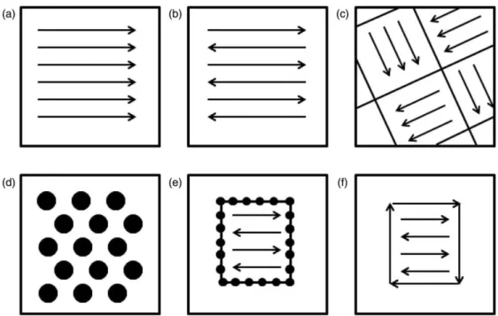
2.2.4.6 Scan Strategy
Various scan strategies have been developed and are depicted in Figure 12. For feed-based systems strategies tend to be relatively simple, such unidirectional (Figure 12a) and bi-directional (Figure 12b). These strategies use rectilinear infill to melt a give part layer. For SLM and EBM, other strategies have been developed besides unidirectional and bi-directional. In SLM, island scanning (Figure 12c) has been used to reduce residual stress [60]. Island scanning is a checkerboard pattern of alternating unidirectional fills and reduces temperature gradients in the scan plane (x–y plane) by distributing the process heat. In EBM, spot melting (Figure 12d, e) is common practice to melt contours, which are boundaries between infill and the powder bed. SLM systems also used contours, though contour melting strategy is typically linear (Figure 12f). Contour passes are done after melting in SLM to refine surface finish [60], whereas in EBM are done prior melting [24].
The scan strategy for a give build can be adjusted by layer or by part, and has a direct impact on process parameters: heat source power and velocity must be optimized for a given scan strategy. The relationship between heat source power and heat source velocity is a key parameter for metal AM processes, as it is important for eliminating process-induced porosity and determining grain morphology [24].
Figure 12 - Scan strategies used to determine heat source path in metal AM as seen in the X-Y plane (perpendicular to the build direction): (a) unidirectional or concurrent fill; (b) bi-directional, snaking, or
countercurrent fill; (c) island scanning; (d) spot melting; (e) spot melting contours with snaking fill; and (f) line melting contours with snaking fill [24].
2.2.4.7 Deposition Strategy
The way in which feedstock is delivered to the melt surface controls deposition rate and can have a strong effect on material defect and properties. In wire feed systems, the vertical and horizontal angle of the wire feed are related to deposition efficiency, surface roughness, incomplete melting, rippling and other processing effects [61]. On the same say, the angle of powder spraying is important for powder feed systems, and in both of them the deposition rate is critically important. The deposition rate and the velocity of the heat source determine how much material is going to be deposited in a given pass. In these systems, the build-up of material must be considered in order to properly choose the layer thickness [24].
For power bed system, the layer thickness determines how much powder is “raked”. A “rake” is a bar that sweeps out powder onto the build surface. The number of passes, mechanical type of rake and the amount of powder being retrieved by pass determine the efficiency of these systems [24].
2.2.4.8 Cracking, Delamination and Swelling
The formation of defects is basically dependent on process temperature. Cracking of the microstructure may occur in solidification or subsequent heating. Macroscopic cracks may relate to other defects like porosity. Delamination may lead to interlayer cracking. If the process temperature is too high, a combination of melt pool size and surface tension may lead to

![Figure 3 – Schematic visualization of AM field and research and development opportunities [12]](https://thumb-eu.123doks.com/thumbv2/123dok_br/18766700.923103/22.892.253.673.326.794/figure-schematic-visualization-field-research-development-opportunities.webp)
![Figure 7 – Generic illustration of an AM powder feed system [27].](https://thumb-eu.123doks.com/thumbv2/123dok_br/18766700.923103/29.892.289.649.113.433/figure-generic-illustration-powder-feed.webp)
![Figure 9 – Overview of relationship between input parameters and underlying physics to meet to expected outcome of metal AM [24]](https://thumb-eu.123doks.com/thumbv2/123dok_br/18766700.923103/33.892.138.798.181.630/figure-overview-relationship-parameters-underlying-physics-expected-outcome.webp)
![Table 5 – Typical layer thicknesses and minimum feature sizes of metal AM processes. Adapted from [24]](https://thumb-eu.123doks.com/thumbv2/123dok_br/18766700.923103/34.892.133.807.146.364/table-typical-layer-thicknesses-minimum-feature-processes-adapted.webp)
![Table 7 – Common post-processing procedures for Ti6Al4V and Inconel 718 [24].](https://thumb-eu.123doks.com/thumbv2/123dok_br/18766700.923103/44.892.116.811.601.902/table-common-post-processing-procedures-ti-al-inconel.webp)
![Table 8 – Some important characteristics of titanium compared to other structural metals [89]](https://thumb-eu.123doks.com/thumbv2/123dok_br/18766700.923103/47.892.134.808.630.997/table-important-characteristics-titanium-compared-structural-metals.webp)
![Figure 17 – Effect of alloying elements on phase diagrams of titanium alloys (schematically) [89]](https://thumb-eu.123doks.com/thumbv2/123dok_br/18766700.923103/49.892.171.765.567.806/figure-effect-alloying-elements-diagrams-titanium-alloys-schematically.webp)
![Figure 19 – Partial Ti-6Al-V phase diagram showing the Ti6Al4V composition line. Adapted from [94]](https://thumb-eu.123doks.com/thumbv2/123dok_br/18766700.923103/51.892.297.640.104.372/figure-partial-phase-diagram-showing-composition-line-adapted.webp)
