Repositório ISCTE-IUL
Deposited in Repositório ISCTE-IUL:
2018-06-04Deposited version:
Post-printPeer-review status of attached file:
Peer-reviewedCitation for published item:
Santos, N., Raimundo, A., Peres, D., Sebastião, P. & Souto, N. (2017). Development of a software platform to control squads of unmanned vehicles in real-time. In 2017 International Conference on Unmanned Aircraft Systems (ICUAS). Miami: IEEE.
Further information on publisher's website:
10.1109/ICUAS.2017.7991529Publisher's copyright statement:
This is the peer reviewed version of the following article: Santos, N., Raimundo, A., Peres, D.,
Sebastião, P. & Souto, N. (2017). Development of a software platform to control squads of unmanned vehicles in real-time. In 2017 International Conference on Unmanned Aircraft Systems (ICUAS). Miami: IEEE., which has been published in final form at
https://dx.doi.org/10.1109/ICUAS.2017.7991529. This article may be used for non-commercial purposes in accordance with the Publisher's Terms and Conditions for self-archiving.
Use policy
Creative Commons CC BY 4.0
The full-text may be used and/or reproduced, and given to third parties in any format or medium, without prior permission or charge, for personal research or study, educational, or not-for-profit purposes provided that:
• a full bibliographic reference is made to the original source • a link is made to the metadata record in the Repository • the full-text is not changed in any way
The full-text must not be sold in any format or medium without the formal permission of the copyright holders. Serviços de Informação e Documentação, Instituto Universitário de Lisboa (ISCTE-IUL)
Av. das Forças Armadas, Edifício II, 1649-026 Lisboa Portugal Phone: +(351) 217 903 024 | e-mail: [email protected]
Development of a Software Platform to Control
Squads of Unmanned Vehicles in Real-Time
Nuno Santos
(1) (2), António Raimundo
(1) (2), Diogo Peres
(1) (2), Pedro Sebastião
(1) (2), Nuno Souto
(1) (2)(1)
ISCTE-Instituto Universitário de Lisboa, DCTI, Avenida das Forças Armadas, 1649-026 Lisboa
(2) Instituto de Telecomunicações, Av. Rovisco Pais 1, 1049-001Lisboa
Email: [email protected]; [email protected]; [email protected]; [email protected]; [email protected]; Abstract— This paper proposes a new software platform to
control and monitor a squad of unmanned vehicles. Through the use of an open-source flight controller and an on-board Raspberry Pi it is possible to create a system that enables communication between a remote ground control stations (GCS) and a unmanned aerial vehicles (UAVs). Both are connected through the use of wireless and cellular networks like Wi-Fi, 3G and 4G which have the required support to allow for communication beyond line of sight.
Keywords— Unmanned Aerial Vehicle, Software platform, Drones, Real-time control, Monitoring
I. INTRODUCTION
Unmanned Aerial Vehicles (UAVs) activities have been increasing in the last decade, what then was mainly used for military purposes is now a leisure activity for many aviation enthusiasts. Radio Control (RC) is the major communication method used between the operator and the drone, however with the most recent developments regarding cellular networks, there is a way of exploring the beyond line of sight limitation that exists in almost all RC controlled vehicles. Some applications of the use of the UAVs include:
• Surveillance of boarders, coastlines and forests as to prevent fires;
• Use in war scenes to prevent human casualties; • The providing of emergency equipment for people in
need of urgent medical care;
• Managing and performing tasks on crops, farms or other workplaces [1];
• Delivering packages and mail autonomously [2]. This paper presents a solution to the beyond line of sight obstacle that consists in a software platform that is able to communicate and interact with one or several drones acting as a Control Tower. Through the use of a central server and a Raspberry Pi (RPi) and the use of cellular networks or Wi-Fi the communication is achieved and makes possible for the control and monitoring of one or more unmanned vehicles.
Besides monitoring and controlling, the software will also serve the purpose for an admin to keep track of all the registered and related users and their respective drones. With such information, the admin will be capable of overriding control, removing access from certain users to the main server, disallowing them and making them incapable of communicating with their previous drone. When controlling, with the use of the on-board RPi and its camera, the users will also have access to a live video feed for a better control.
In section 2 the UAVs categories are explained as well as their connection to Ground Control Stations (GCSs). The application UI is described in section 3. In section 4 the applications control system is explained. Section 5 details the communication architecture of the application. The final conclusions and future work are presented on the last chapter.
II. UNMANNED AERIAL VEHICLES
To understand the way UAVs work it is important to first know the different categories these vehicles are categorized for. The main hardware and blocks that compose a UAV are also going to be described in this section.
A. UAVs categories
UAVs can be categorized according to three main characteristics: range, size and altitude. Typically, the higher the drone goes, the heavier it is and the larger its range. According to this it is possible to categorize each UAV in the following way: Category Total Weight [kg] Range [km] Endurance [h] Altitude
HALE 2500 – 12500 global Trans 24 – 48 15000 – 20000
MALE 1000 – 1500 <500 24 – 48 5000 – 8000 TUAV 150 – 500 100 – 300 6 – 10 3000 – 5000 Close Range UAV 150 100 2 – 4 3000 Mini UAV < 30 30 < 2 150 – 300 Micro UAV 0.1 20 < 1 250
The table above describes how the different UAVs categories differ from each other, the description of each of these categories is:
• HALE: High Altitude Long Endurance; • MALE: Medium Altitude Long Endurance; • TUAV: Medium Range;
• Close range; • Mini UAV; • Micro UAV.
This paper is focused on the Mini UAV as it is the most commonly used and the most affordable along with the Micro
UAV. Categories like HALE, MALE and TUAV are more common for military use.
B. Main components
For each of these categories the main blocks differ and the components that are part of each UAV differ. This paper focuses on the Mini UAV category, and the components that are part of the system are:
• Main frame
• Electronic Speed Controller (ESC) • Flight Controller • Motors • Battery • Navigation Systems • Raspberry Pi. 1) Main frame
The main frame holds all the components and can have several configurations possible depending on the number of motors used, the number of components as well and the payload. This paper focus is on a hexacopter frame, which gives room for six motors
2) Electronic Speed Controller
The ESC is responsible for varying the speed of the electric motors, they are connected to the power distribution board which is connected to the batteries.
3) Flight Controller
The flight controller is the unit responsible for controlling the UAV, it communicates with the ESCs to control the motors which enable the drone to fly according to the given commands. The flight controller used was the Pixhawk. The Pixhawk is an open-hardware project aimed at providing a high-end autopilot hardware at low cost, its main specifications are:
• 168 MHz / 252 MIPS Cortex M4F
• 14 PWM / Servo outputs (8 with failsafe and manual override, 6 auxiliaries, high-power compatible) • Abundant connectivity options for additional
peripherals (UART, I2C, CAN, micro-USB)
• Integrated backup system for in-flight recovery and manual override with dedicated processor and stand-alone power supply (fixed-wing use)
• Backup system integrates mixing, providing consistent autopilot and manual override mixing modes (fixed wing use)
• Redundant power supply inputs and automatic failover
As the Pixhawk is an open-hardware project it makes possible for its study and use.
4) Motors
Motors along with the propellers are responsible for generating the thrust needed to lift the UAV. When building a UAV, it’s important to choose the right motors as it is needed to have in consideration the thrust to weight ratio. As is the case with multi-rotors it is important that the motors
can produce around 50% more thrust than the total weight of the drone [5].
5) Battery
The batteries are the UAVs power supply. They provide the power to all the components present in the UAV. When choosing batteries to deploy on the drone it is important to consider their weight and the power they are able to output.
6) Navigation Systems
Navigation systems are crucial for the piloting of the UAV. The user needs to know the drone’s position accurately at all times in order to accurately monitor from the application and this is possible through the use of a GPS connected to the flight controller. The use of navigation systems also allows for autonomous flight, meaning the UAV is able to follow a pre- defined path with the use of the GPS.
7) Raspberry Pi
The Raspberry Pi (RPi), is a credit card sized computer used with the main purpose of connecting the UAV and its flight controller to the application. Through the use of the USB port, it is possible to connect the RPi to the Pixhawk, via micro-USB port present in the flight controller, gather telemetry and send it to the application. Connecting the RPi to cellular networks it is possible to connect to the application in order to send commands to the UAV and also for the receiving telemetry data. Raspberry Pi was used for its simplicity, reliability and for having a big support community, which was important to solve minor problems throughout the development process.
III. APPLICATION USER INTERFACE
The application is built using the Java programming language, being JavaFX the API used for the making of the GUI. The whole system is comprised with the Java application, the public server which is critical in the redirecting of messages and the RPi, present on the drone to establish the communication with the flight controller. The application serves as Ground Control Station (GCS) for each drone and is named Control Tower (CT), as it resembles the job done by the commonly known airports Control Towers. A. User interface
The user interface (UI) part of the application is composed by three different screens:
• Login Screen; • Monitoring Screen; • Controlling Screen.
As the application is built using JavaFX, this means that each different screen is represented by a FXML file, containing the code that represents each screen. An example of the code contained in a FXML file, more specifically, the code representing a text field, a password field and a button for the Login screen, can be seen in figure 1.
Fig. 1. Code snippet from the Login.xml.
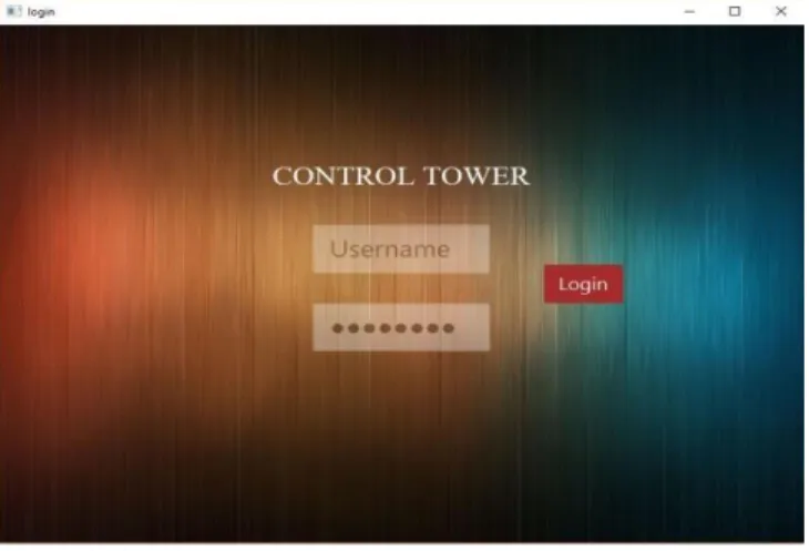
The code represented in Figure 1, originates in the login screen, two input fields, text and password, and a button so that the user can login to the application and consequently to the server. Figure 2, shows the layout of the login screen and how it is represented.
Fig. 2. The login screen.
After successfully logging in and connecting to the main server, the user advances to the monitoring screen. Here, and on the server, two types of users can be distinguished, the admin whom is capable of monitoring and controlling other user’s drones, and a regular user who is only capable of monitoring or controlling its assigned drones. As it will be better explained on section 4 this difference in each user’s credentials serves different purposes for the end user. In figure 3, the monitoring screen is shown.
Fig. 3. Monitoring Screen.
In figure 3, the regular user monitoring view is shown, on the left the telemetry received from each drone is received and shown. On the right, two lists are present, the upper right one will show all the available drones for the admin to control and monitor, the bottom one shows which users are connected at the moment and to which drone. The last screen is the controlling screen, it serves the purpose for the user to
connect and control the vehicle. Two modes of controlling are available: manual and autonomous. These two modes will be better explained in section 4. The controlling view also enables for the user to choose between several flight modes each with a different purpose and shows the UAV telemetry received live. Figure 4 shows the controlling screen.
Fig. 4. The Controlling screen
IV. APPLICATION SYSTEM
The application is divided into two main blocks, monitoring and controlling which independently perform different tasks a play a different role.
A. MAVLink
Micro Aerial Vehicle Link (MAVLink) is the protocol used for the exchanging of messages between the CT and the Pixhawk. It is a header only message library, first released in 2009 by Lorenz Meier, its current version is 1.1. Figure 5 shows the structure of the MAVLink packet.
Fig. 5. MAVLink packet structure. Source: qgroundcontrol.org/mavlink
B. Monitoring
The monitoring process consists on the monitoring of all the information regarding connected drones. By switching MAVLink messages with the server and the RPi on the UAV it is possible to get the drones location, its information status, the user to which it is connected at that moment and if the user is logged in as the Admin it is possible to override the control of other users.
1) Telemetry
By switching MAVLink messages with the UAV, it is possible to gather telemetry from the flight controller and consequently the application is able to gather from the messages information like the altitude, heading, groundspeed, vertical speed and throttle. Information from flight modes can also be gathered. During the monitoring phase, the most important data to be received are the MSG_GPS MAVLink type messages, which communicate the GPS positioning and coordinates of the UAV, allowing
for the user to receive its location and track its movement on the application.
2) Control Overriding
The primary feat of the CT is the control overriding. This feature, allows the admin to take or give control to determined users according to its preference. This is mostly useful for security purposes, for example, having a squad of drones controlled by different users and performing different tasks the admin can monitor if all the users have an adequate behavior when piloting. The control overriding is achieved by interacting with the server, as all the information is stored in it.
By exchanging messages with the server the Admin is able to get the connected users control and override its connection, being then in charge of its assigned drone and control it. By performing changes in the database the overridden user will not be able to enter the application until the Admin gives the control and grants the access again. The flowchart depicted in figure 7 better explains this interaction.
Fig. 6. Overriding and giving control flowchart.
C. Controlling
The control part of the CT allows for the user to remotely command the drone, and it features two main points, the manual and autonomous control.
1) Manual Control
To describe how the manual control works it’s important to first understand some basic principles on how multi-rotors are able to fly. There are 3 axis involved when a drone is moving, yaw, pitch and roll. Yaw axis represents the rotation movement of the drone, roll axis represents the side movement making the drone go left or right and the pitch axis tilts the UAV forward or backward making it accelerate or decelerate. When manually controlling a drone the flight controller is in charge of converting the received commands in order to make the motors speed increase or decrease to make the drone have movement. This is achieved by the CT communication with the drone through the use of the MAVLink message MSG_RC_CHANNELS_OVERRIDE. A gamepad can be used to manually control the UAV as it resembles the ones used in RC through the use of the analog sticks. As each gamepad has two analog sticks, one can be used to control throttle values and the other can be used to change the roll and pitch axis values so that the UAV can
change direction or go forward and backwards. Figure 7 represents the axis present in each gamepad analog sticks.
Fig. 7. Gamepad Analog sticks axis. Source: [6]
The MSG_RC_CHANNELS_OVERRIDE has to have values between 1000 and 2000, each representing the minimum and lowest control values. For this to happen equation 1 has to be applied to the analog values and convert them to the scale needed to be interpreted by the flight controller.
𝑐ℎ𝑎𝑛𝑛𝑒𝑙𝑉𝑎𝑙𝑢𝑒 = 𝑠𝑙𝑜𝑝𝑒×(𝑥|𝑦) + 𝑖𝑛𝑡𝑒𝑟𝑐𝑒𝑝𝑡 (1) where slope = 500,
intercept = 1500,
x|y = input coming from the analog stick 2) Autonomous Control
The autonomous control is achieved through the use of waypoints navigation. This method enables the flight controller to receive GPS coordinates, and stores that information in the form of waypoints. Then when the user commands it to start, the flight controller knows the waypoints order and starts flying the drone to the correct location at the specified altitude through each one. MAVLink has what it calls the Waypoint Protocol. This protocol describes how waypoints are sent and read from the UAV in order to ensure the consistency of information between the sender and the receiver [7]. Three different types of communication between UAV and the CT can be done regarding the waypoints protocol: read, write and clear.
V. SERVER AND STREAMING
To have the CT communicate with the RPi on the UAV over the internet they both need to know each other’s IP addresses. Due to both these applications being behind NATs there is no way they can effectively communicate directly. The server manages to solve the NAT problem, using a public IP address both the CT and RPi can have access to the server, log in and switch MAVLink messages between each other [8]. By having an active database, the server is able to register all users and their respective assigned drones. When connecting, the server is able to register the user IP address, and encapsulate each MAVLink message when forwarding them to the CT, this way when the CT receives each MAVLink message it is able to unpack each message, store the IP address, and distinguish between each user.
A. Streaming
In order to have live video streaming from the RPi Camera from the drone two approaches were studied and tested, one used Wowza Streaming Engine as a streaming server to redirect the stream from the RPi Camera to the
Control Tower and the other was through html5 video stream through web sockets. The use of Wowza proved not to be the best solution when streaming to the CT, as it was only able to be done using the RTMP protocol as some others like HLS were not suitable for real-time streaming. As the application was developed using JavaFX, the RTMP protocol is not playable and doesn’t have native support due to it requiring Flash to play, as such, it no longer became a valid alternative. The project chosen was developed and introduced by Phoboslab and it consisted on the live-streaming through web-sockets and html5 [9]. Using this, it was possible to get a real-time video feed on the CT. Whilst not tested extensively, when the RPi was connected to Wi-Fi the delays averaged around 260 ms, when using 3G/HSPA technology the delays averaged around 310 ms and when using 4G/LTE the delays averaged around 300 ms
VI. CONCLUSIONS AND FUTURE WORK
This paper introduces a new application that can be used to remotely control and monitor a squad of UAVs. This can be particularly useful for when a user needs to have several drones performing a type of work and wants to monitor their performance, having the possibility to control any of the connected drones whether they are being controlled by another user or not. One of the main goals is to achieve real-time communication, and that is done by having a live video feed received allowing for the user to remotely control behind line of sight. As future work, more tests will have to be made regarding the autonomous and manual control outside of laboratory *conditions. Also, some more tests have to perform on the live video streaming to ensure a higher quality of service. Some improvements can also be made to the application UI, making it more responsive, adding extra-features and implementing more failsafe solutions.
ACKNOWLEDGEMENTS
The work developed and presented in this paper was supported by Instituto de Telecomunicações at ISCTE-IUL.
REFERENCES
[1] Global Research News, Unmanned Aerial Vehicles (UAV): Drones for Military and Civilian Use. Global Research. [Online] 21 March 2014. [Cited: 7 December
2016.] Available from:
http://www.globalresearch.ca/unmanned-aerial-vehicles- uav-drones-for-military-and-civilian-use/5374666.
[2] J. D'Onfro, Why Amazon Needs Drones More Than People Realize. Business Insider. [Online] 30 July 2014. [Cited: 10 December 2016.]
Available from:
http://www.businessinsider.com/amazon-drones-2014-7.
[3] R. Austin, Unmanned Aircraft Systems, UAVs Design, Development and Deployment. s.l. : Wiley, 2010.
[4] MF Bento, Unmanned Aerial Vehicles An Overview. 2008, InsideGNSS. pp. 54-56.
[5] Alex and Sam, How to choose the right motor for your multicopter drone. Drone Trest. [Online] October 2015.. [Cited: 30 November 2016.] Available
from: http://www.dronetrest.com/t/how-to-choose-the-right-motor- for-your-multicopter-drone/568
[6] A. Davison, Chapter 28.9. Building a Game Pad Controller
with JInput. 2006.
[7] QGroundControl: Waypoint protocol. QGroudControl. [8] QGroundControl MAVLink. QGroundControl. [Online] [Cited: 5 December 2016] Available from: http://qgroundcontrol.org/mavlink/start.
[9] D. Szablewski,, HTML5 LIVE VIDEO STREAMING VIA WEBSOCKETS. [Online] [Cited: 30 October 2016] Available from Phoboslab: http://phoboslab.org/log/2013/09/html5-live-video-streaming-via-websockets .
![Fig. 7. Gamepad Analog sticks axis. Source: [6]](https://thumb-eu.123doks.com/thumbv2/123dok_br/18396652.893661/5.918.78.435.441.650/fig-gamepad-analog-sticks-axis-source.webp)
