í
ã
ã ! " í # $ í
%
%
%
Acknowledgements
The accomplishment of this thesis was only possible due to the contribution of several people, to whom I want to thank.
First of all I would like to express my gratitude to my supervisor Professor Dr. Ana Aguiar Ricardo for hosting me in her lab and for all the help, orientation and transmitted knowledge during these months of work. It was very good to be a part of professor team and to learn about research and the supercritical world.
To Márcio Temtem I want to give a very special thank. He was my advisor, colleague and friend inside and outside the lab and taught me numerous important things. Thank you for the endless help and patience!
The collaboration with Professor Dr. Cláudia Lobato and Pedro Andrade from Instituto Superior Técnico (IST) was fundamental in the work with cells and very important for future work development. Thank you very much!
I also want to thank to all the people that helped me and supplied the necessary equipment to perform this work: Professor Dr. João Sotomayor with contact angles, Professor Dr. Isabel Fonseca with mercury porosimeter, Professor Dr. Helena Godinho and Dr. Pedro Almeida with Dynamic Mechanical Analysis (DMA), Isabel Nogueira (IST) with Scanning Electron Microscopy (SEM), Joana Pais and Mariana Costa with freeze-dryer and Mrs. Conceição and Mrs. Idalina with lab materials.
A last and singular acknowledgement to my family and friends, particularly, my parents and sister that always support me.
To everyone else that I did not mentioned, but that in some way helped me to get here.
Resumo
Neste trabalho desenvolveram-se novos materiais porosos para aplicações biomédicas utilizando tecnologia supercritica. Neste contexto, preparam-se dois tipos de materiais constituídos por quitosano e álcool polivinílico (PVA) em diferentes proporções: membranas e matrizes tri-dimensionais (3D). As membranas foram preparadas utilizando o método de inversão de fases e usando como não-solvente o dióxido de carbono supercrítico (scCO2). Os
resultados obtidos na caracterização destes materiais revelaram que a presença de PVA nas membranas provoca a diminuição da porosidade e do ângulo de contacto e o aumento na interconectividade entre os poros e na capacidade de inchar. As propriedades mecânicas também se alteraram devido à presença de PVA nas membranas, aumentando a capacidade de elongamento e fazendo diminuir o valor da máxima tensão suportada. As matrizes 3D foram preparadas por liofilização e foram reticuladas com glutaraldeído, utilizando uma técnica assistida por CO2. A optimização deste processo de reticulação envolveu o estudo de
Abstract
In this work new porous materials for biomedical applications were developed using supercritical fluids (SCF) technology. In this context, two types of porous structures constituted by blends of chitosan and poly (vinyl alcohol) (PVA) using different ratios were prepared: membranes and three dimensional (3D) scaffolds. Phase inversion method using supercritical carbon dioxide (scCO2) as non-solvent was used to prepare porous membranes.
The characterization of these materials showed that the presence of PVA in the membranes composition causes a decrease in porosity values and contact angle and an increase on pores interconnectivity and swelling degree. The mechanical properties were also modified by the existence of PVA in the membranes composition, increasing the elongation capacity of these structures and decreasing the supported break stresses. The 3D-scaffolds were prepared using freeze-drying technique and were treated with glutaraldehyde using a CO2-assisted
List of Symbols
3D – Three-dimensional CHT – Chitosan
DMA - Dynamic mechanical analysis DSC - Differential Scanning Calorimetry E – Young’s modulus
FBS - Fetal Bovine Serum SCF – Supercritical Fluid
PBS - Phosphate Buffered Saline Pc – Critical Pressure
PVA – Poly (vinyl alcohol)
RPMI - Roswell Park Memorial Institute medium scCO2 – Supercritical carbon dioxide
SEM - Scanning Electron Microscopy T - Temperature
Table of contents
I. Introduction... 1
1. Supercritical Carbon Dioxide... 1
2. Supercritical Fluids based methods for porous structures production ... 4
2.1. Gas foaming ... 4
2.2. Supercritical fluid emulsion templating ... 6
2.4. Phase inversion... 8
3. Freeze-drying method ... 13
4. Crosslinking process ... 15
5. Biomaterials in tissue engineering ... 17
6. Aim and outline of this thesis... 22
7. References ... 24
II. Porous structures – Membranes and 3D-scaffolds...35
1. Introduction...35
2. Experimental...36
2.1. Materials ...36
2.2. Membranes preparation ...37
2.3. Scaffolds preparation ...40
2.4. Characterization ...43
2.5. In vitro biodegradation studies ...45
2.6. Cytotoxicity assay...45
3. Results and discussion ...47
3.1. Membranes preparation and characterization ...47
3.2. Scaffolds preparation and characterization...54
Index of Figures
Chapter I
Figure 1.1 - Schematic representation of the change from liquid-gas equilibrium (T<Tc) to supercritical fluid (T>Tc) conditions as a substance is heated above its critical
temperature and pressure... 1
Figure 1.2 - Variation of density with pressure for pure CO2 at 35ºC.At this temperature (i.e., above Tc for CO2) there is a rapid but continuous increase in density near the critical pressure (Pc)... 2
Figure 1.3 - Pressure-temperature phase diagram of pure CO2 and representation of critical point (Tc = 31.1 ºC and Pc = 7.38 MPa)... 3
Figure 1.4 - Schematic of the preparation of porous materials using supercritical fluid emulsion templating. The external phase is an aqueous solution and the internal droplet phase is scCO2... 7
Figure 1.5 - a) Schematic representation of an isothermal phase diagram for the system polymer-solvent-non-solvent at pressures above the critical point of the binary mixture solvent+CO2; b) obtained structures at different composition paths: (1) dense structure, (2) cellular morphology, (3) bicontinuous morphology and (4) microparticles ... 13
Figure 1.6 - Schematic representation of emulsion freeze-drying process ... 14
Figure 1.7 - Schematic representation of (a) chitosan and (b) PVA crosslinked with glutaraldehyde ... 16
Figure 1.8 - Equilibrium of glutaraldehyde in aquous solution ... 16
Figure 1.9 - Structures of chitosan and PVA... 19
The principle of tissue engineering ... 21
3.4. Cytotoxicity assay ... 66
4. Conclusions ... 71
Chapter II
Figure 2.1 – Schematic diagram of the high pressure apparatus used where (1) Gilson
305 Piston Pump; (2) Gilson 306 Piston Pump; (3) Temperature controller (Hart Scientific, Model 2200); (4) High pressure cell; (5) Pressure transducer (Setra Systems Inc., Model 204); (6) Back pressure regulator (Jasco 880-81); (7) Water recirculating pump; (8) Visual thermostated water bath ... 37
Figure 2.2 – Photograph of the experimental high pressure apparatus and detail of the
high pressure cell... 38
Figure 2.3 – Pictures of the chitosan membrane in the stainless steel cap immediately
after preparation and removal from the high pressure cell: (a) top view and (b) lateral view. ... 39
Figure 2.4 – Schematic diagram of the high pressure apparatus used where (1) Gilson
305 Piston Pump; (2) Gilson 306 Piston Pump; (3) Temperature controller (Hart Scientific, Model 2200); (4) High pressure cell containing the scaffold samples; (5) Pressure transducer (Setra Systems Inc., Model 204); (6) Back pressure regulator (Jasco 880-81); (7) Water recirculating pump; (8) Visual thermostated water bath; (9) High pressure cell containing glutaraldehyde solution ... 41
Figure 2.5 - Photograph of the (a) DMA equipment and (b) detail of the membrane
sample placed between the two clamps... 44
Figure 2.6 – SEM images of cross-section and surface top view of membranes with
different PVA content: a) 100CHT; b) 90CHT; c) 75CHT; d) 50CHT; e) 100EVAP. ... 49
Figure 2.7 - Stress-strain curves obtained for the membranes under (a) dry conditions and
(b) wet conditions (soaked in PBS during 1 hour). ... 53
Figure 2.8 – Influence of: (a) freezing temperature and (b) composition in the pore size
Figure 2.9 – 3D-scaffolds prepared with 3% (w/w) of polymer in the casting solution: (a)
picture of chitosan scaffold frozen at -20ºC (100CHT_3% -20ºC); (b) and (c) SEM images of chitosan scaffold frozen at -50ºC (100CHT_3% -50ºC) from two different regions; and SEM images of blended scaffolds frozen at -20ºC with: (d) 90% chitosan (90CHT_3% -20ºC), (e) 75% chitosan (75CHT_3% -20ºC) and (f) 50% chitosan (50CHT_3% -20ºC). ...58
Figure 2.10 – Dynamic swelling of crosslinked 3D-scaffolds with 3% (w/w) of polymer
concentration and frozen at -50ºC using different concentrations of glutaraldehyde and operation times...60
Figure 2.11 – Dynamic swelling of 3D-scaffolds prepared with 3% (w/w) of polymer
concentration, frozen at -20ºC and crosslinked with 1% (v/v) of glutaraldehyde using different PVA ratios...61
Figure 2.12 – Degradation curves of membranes in (a) PBS solution and (b) PBS
solution containing lysozyme ...63
Figure 2.13 – SEM images of 90CHT membranes after 30 days in PBS solution
containing lysozyme: (a) cross section (300x) and (b) surface top view (1000x)...64
Figure 2.14 – Degradation curves of 3D-scaffolds in (a) PBS solution and (b) PBS
solution containing lysozyme ...65
Figure 2.15 – SEM images of 100CHT scaffold after 65 days in PBS solution containing
lysozyme in different regions and using different magnifications (a) 800x and (b) 400x...66
Figure 2.16 – Representative images of L929 fibroblast cells cultured in (a) 100CHT, (b)
Index of Tables
Chapter I
Table 1.1 – Comparison of typical physical properties of gases, SCFs and liquids... 1
Table 1.2 – Critical conditions of a few substances ... 2
Chapter II Table 2.1 – Composition of membranes and operation time... 39
Table 2.2 – Summary table of 100CHT scaffolds for different operation conditions... 40
Table 2.3 – Operation conditions for crosslinking process using a sample tube with an inner diameter of 1.2 cm and 3 cm height... 42
Table 2.4 – Operation conditions for crosslinking process using a sample tube with an inner diameter of 1.8 cm and 4 cm height... 42
Table 2.5 – Influence of composition in membranes morphology... 48
Table 2.6 – Influence of membranes composition in contact angle and swelling degree ... 52
Table 2.7 – Influence of membranes composition in Young’s modulus... 54
Table 2.8 – Influence of the casting solution concentration in pores morphology of 3D-scaffolds ... 55
Table 2.9 – Response of L929 fibroblast cells cultured in the membranes... 67
Table 2.10 – Response of L929 fibroblast cells cultured in the 3D-scaffolds... 69
Figure 2.17 – Cytotoxicity tests of the membranes following the ISO standards for biomaterials. Negative control: tissue culture plate control (polystyrene); Positive control: 0.01 M phenol. ...68
I. Introduction
1. Supercritical Carbon Dioxide
A Supercritical Fluid (SCF) is defined as a substance above its critical pressure (Pc) and temperature (Tc), where the density of the gas phase becomes equal to the density of the liquid phase and the interface between liquid and gas disappears1 (Figure 1.1).
Figure 1.1 - Schematic representation of the change from liquid-gas equilibrium (T<Tc) to
supercritical fluid (T>Tc) conditions as a substance is heated above its critical temperature and
pressure (adapted from Cooper et al. 2).
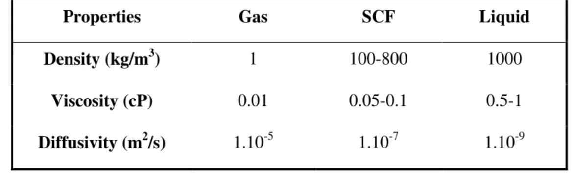
SCFs combine the properties of the two phases, presenting gas-like diffusivity and viscosity and liquid-like density as shown in Table 1.1. In addition, SCFs are highly compressible and their density, and therefore the solvent properties, can be tuned over a considerable range by varying the pressure.3 Figure 1.2 shows the rapid and continuous increasing in density for pure CO2 near the Pc and for a temperature above Tc.2
Table 1.1 – Comparison of typical physical properties of gases, SCFs and liquids
Properties Gas SCF Liquid
Density (kg/m3) 1 100-800 1000
Viscosity (cP) 0.01 0.05-0.1 0.5-1
Diffusivity (m2/s) 1.10-5 1.10-7 1.10-9
Figure 1.2 - Variation of density with pressure for pure CO2 at 35ºC. At this temperature (i.e., above
Tc for CO2) there is a rapid but continuous increase in density near the critical pressure (Pc) (adapted
from Cooper et al.2).
The SCF technology involves high pressures and sometimes high temperatures (Table 1.2) and most of the times it will be easier to carry out the experiments under conventional conditions. Even so, there are several advantages when using these fluids for a variety of applications.4
Table 1.2 – Critical conditions of a few substances
Substance Tc (ºC) Pc (MPa)
Carbon dioxide 31.1 7.38
Water 374.2 22.1
Methanol 239.9 8.08
Ethane 31.9 4.87
Propane 96.7 4.25
Toluene 318.6 41.1
Supercritical carbon dioxide (scCO2) is the most used SCF because it is an environmentally
benign solvent, non-toxic, non-flammable, low cost and readily available in high purity from several sources. Besides, it has an accessible critical point with a Tc of 31.1 °C and a Pc of 7.38 MPa (Figure 1.3).
Figure 1.3 – Pressure-temperature phase diagram of pure CO2 and representation of critical point
(Tc = 31.1 ºC and Pc = 7.38 MPa).
In recent years, scCO2 has been widely used as a solvent, anti-solvent and plasticizer for
synthesis, modification and purification of both synthetic and natural polymers. Therefore, the solvent properties of scCO2, i.e. the solubility of polymers in scCO2 and the solubility of
scCO2 in polymers, are very important parameters.5
ScCO2 is a very poor solvent for most polymers and pharmaceutical compounds and the
polarity of polymers can be a reason for their limited solubility. In addition, CO2 has the
that CO2 might solubilise dipolar and non-dipolar molecular systems through site-specific
solute-solvent interactions.6 Beckman et al.7,8 have shown that by careful molecular design and choice of co-monomers to balance the solvent–solute and solute–solute interactions it is possible to prepare hydrocarbon based copolymers that are CO2-soluble. Furthermore, CO2
solubility and diffusivity in polymers are influenced by both the molecular structure (the interaction between CO2 and molecular chains) and the morphology (crystalline or
amorphous, related with free volume) of polymers.5
2. Supercritical Fluids based methods for porous structures production
Porous structures can be prepared using different methods by means of SCF technology like gas foaming9, supercritical fluid emulsion templating10 and phase inversion.11,12,13
2.1. Gas foaming
The formation of polymer foams occurs when a polymer, plasticized by saturation in the supercritical fluid is rapidly depressurized at a constant temperature. Pockets of gas nucleate and grow in the polymer as the pressure is released and as the supercritical fluid leaves the polymer, the glass transition temperature (Tg) increases. At the point where the Tg for the polymer is higher than the foaming temperature, the porous structure is set.5
Mooney et al.14 prepared highly porous matrices from poly (lactic-co-glycolic acid) (PLGA) using gas foaming method. However, the scaffolds surface was formed by a non-porous film, making them unsuitable for cell ingress, and presenting a barrier for cell nutrients and for waste products of cell metabolism. This may happen due to the rapid diffusion of the CO2
foam, the porogen was leached out by incubation in water for 48 hours. This created a scaffold with an interconnected pore network open to the surface, which was shown to be accessible to cultured smooth muscle cells. Interconnectivity of the pores could be improved even further by partially fusing the salt porogen by exposure to 95% humidity.15
The leaching of the porogen is a major disadvantage of the gas foaming/particulate leaching process since it results in the loss of the majority of any incorporated growth factor. This can be overcome somewhat by encapsulating the active factors in alginate beads which are then incorporated into the compressed polymer together with the porogen before processing. In addition to the issues surrounding salt leaching, the gas foaming process suffers from relatively long manufacturing time.16
Under supercritical conditions, CO2 foams polymers to create porous scaffolds suitable for
tissue engineering applications. Since increasing pressure, increases the rate of gas diffusion into polymer systems, equilibration time is reduced compared to subcritical pressures.17 Gas saturation equilibration times as low as 10 minutes have been reported.18,19 The effectiveness of this technique in foaming PLGA and use of the scaffolds for tissue engineering has been demonstrated both in vitro and in vivo.20,21,22
Barry et al.23 used scCO2 to foam the non-degradable polymer poly(ethylmethacrylate)/
porogen/leaching process is not necessary. As might be expected, as porosity increases, mechanical strength decreases and this is an important factor in many biomedical applications. There is therefore an upper limit, above which pore size and low mechanical strength precludes their use in certain applications.24
In attempting to improve the mechanical properties of the THFMA for soft prosthetic applications, the foaming of blends of THFMA with styrene–isoprene–styrene copolymer elastomer has been investigated. Mechanical testing revealed the blends to be elastomeric, and these systems may therefore lend themselves to use as scaffolds for particular tissues, such as cartilage. The degree of porosity and interconnectivity of the pores could be tuned by modifying the blend composition and processing temperature, with a reduction in the degree of foaming as temperature increased.25
Similarly, Mathieu et al.18 have shown that the morphology of the foams can be controlled to mimic the bone structure. They found that by controlling the cooling rate of the foamed polymer and the density of the gas nucleation similar bone structures could be formed. Rapid cooling creates many spherical pores while slower cooling permits pores elongation. Alternatively, the interconnectivity of the pores can be improved by post-processing the scaffolds generated by gas foaming using ultrasound. Wang et al.26 produced polymer foams of poly(lactic acid) (PLA) (using sub-critical pressures of CO2) and exposed them to pulsed
ultrasound at a frequency of 20 kHz and average power input of 100 W. This not only slightly increased pore size, but also improved their interconnectivity as a result of pore wall rupture.
2.2. Supercritical fluid emulsion templating
internal phase (usually > 75%), which can be difficult to remove after the reaction. For example, for inorganic materials temperatures > 600°C are often used, which would clearly not be appropriate for thermolabile materials or those containing growth factors for regenerative medicine.
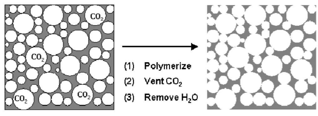
Butler et al.27 demonstrated that the emulsion templating principle can be applied to supercritical CO2-in-water (C/W) emulsions. Using perfluoropolyether (PFPE) surfactants
and PVA to stabilize the C/W emulsions of acrylamide polymers, they vented the CO2
following polymerization, leaving polymer scaffolds with interconnected pores (Figure 1.4). Increasing the volume fraction of the CO2 internal phase increased porosity, and increasing
the surfactant concentration led to more open interconnected structures.
Figure 1.4 - Schematic of the preparation of porous materials using supercritical fluid emulsion
templating. The external phase is an aqueous solution and the internal droplet phase is scCO2 (adapted
from Butler et al. 10).
A disadvantage of this protocol for bioengineering applications is the use of a non-degradable surfactant, and the mean pore sizes (~50 m) produced may not be suitable for all applications — it has been reported that scaffolds for bone regeneration for example require pore sizes between 200 and 400 m.28
A variation on the emulsion templating technique has recently been reported by Partap et al.29, who produced emulsion templated alginate hydrogels in which the scCO2 not only
its chelated form, freeing it to crosslink the alginate and form the porous hydrogel. Calling the technique “reactive emulsion templating”, they were able to produce 3D hydrogels with an open and interconnected porous network, with a mean pore size similar to the emulsion templating technique reported by Butler et al.10.
2.4. Phase inversion
The majority of porous membranes are prepared from a homogenous polymer solution by the wet phase inversion method. In this method, a homogeneous polymer solution is loaded on a support and immersed in a coagulation bath containing a non-solvent. The formation of the porous structure occurs due to the exchange of solvent and non-solvent that causes a decrease in solvent power and the polymer precipitates. So, the affinity between solvent and non-solvent, as well as polymer concentration, temperature, humidity, evaporation time and composition of the casting solution are very important parameters that allow the control of membrane morphology.11,12,13
One of the main concerns when using this method is that some solvents are volatile, flammable and may cause risk to health and environment. For this reason and due to the presence of residual solvents that can cause potential problems in biomedical applications, membranes are normally submitted to intensive post-treatments. Moreover, long formation times and a limited possibility to modulate cell size and membrane structure characterize this process.
Kho et al.30 used a new technique in which scCO2 is used to induce the phase separation of
the polymer solution. Compared with the wet phase inversion method, advantages of this phase separation process can be:
(1) ScCO2 can dry the polymer membrane rapidly and totally without the collapse of the
(2) It is easy to recover the solvent; the solvent dissolved in scCO2 can be removed from
gaseous CO2 in a separator located downstream the membrane formation vessel.
(3) CO2 is not toxic, not flammable and low cost.
Kho et al. used compressed CO2 for the formation of Nylon 6 membranes. A 15% (w/w)
Nylon 6 polymer solution was prepared by dissolving Nylon 6 in 2,2,2-trifluoroethanol. Thin film with thickness ranging from 150 to 250 m was obtained. The process was performed at 35ºC with the final pressure up to 17.4 MPa, for 30 minutes. These authors obtained uniform structures with cellular pores 0.4 m in diameter. They described the structural gradient and pore characteristics of the membranes by a competition between a liquid–liquid (L–L) demixing, that originates soft cellular pores and solid–liquid (S–L) demixing, that originates rough structures. The authors concluded that reducing the relative strengths of both the solvent and the non-solvent, led to membrane pore structures dominated by crystallization (S– L demixing), that is the thermodynamically favoured demixing process, rather than L–L demixing, which is kinetically favoured.
Another membranes formation process, in which scCO2 is used as non-solvent, has been
presented by Matsuyama et al.31. The process consists of the introduction of CO2 into a
membrane formation cell through a buffer tank using a valve that connects the two vessels. After the system has been equilibrated (for 15 minutes) at the pressure of 130 bar, a second valve is opened and CO2 flows in the cell to dry the phase-separated polymer solution.
Matsuyama et al. studied the formation of thin polystyrene membranes analysing the effect of several process conditions (temperature, pressure, polymer concentration). They observed that the average pore size ranged from 8 to 35 m changing pressure (from 75 to 150 bar), polymer concentration (from 15 to 30% (w/w)) and temperature (from 20 to 70ºC).
(w/w)) and tested four solvents: acetone, methyl acetate, 1,3-dioxolane and 2-butanone. They noted that, as the mutual affinity between the solvent and CO2 decreases, the membrane
porosity and the pores size increases.
Using the scCO2 assisted phase inversion method, Reverchon and Cardea13 studied the
formation of cellulose acetate membranes from acetone, polysulfone membranes from N-methylpyrrolidone and chloroform, poly-L-lactide membranes from chloroform, and poly(methyl methacrylate) membranes from dimethylsulfoxide, acetone, and tetrahydrofuran. The overall result of these studies is that, changing the supercritical based process parameters, it is possible to modulate cell and pore size and to obtain various morphologies using the same liquid solvent: cellular structure, binodal structure, and microparticles. In some cases, it is also possible to modulate all membrane characteristics simply changing the non-solvent power of scCO2.
Temtem et al. 11 studied the solvent affinity and depressurization rate on the morphology of polysulfone (PS) membranes produced by CO2-assisted phase inversion method, of six
different organic solvents and two depressurization rates. This study showed that mutual affinity between solvent and non-solvent and the depressurization rate influence the membranes morphology when scCO2 is used as non-solvent. They also studied the
preparation of membranes with polysulfone/polycaprolactone (PS/PCL) blends using a CO2
-assisted phase inversion method.12 The CO2 capability to swell PCL and decrease the Tm was
used to produce and control the porosity and the properties of the membranes. In this study it was shown that CO2-assisted phase inversion method combined with the capability of CO2 to
act as a blowing agent can be used to produce PS/PCL membranes. By adjusting the PS/PCL ratio it was possible to vary the morphology, the hydrophilicity and the mechanical performance of the membranes. This was the first attempt to combine CO2 foaming ability
In conclusion the use of scCO2 as a non-solvent allows the preparation of sterile and ready
to use devices, since CO2 is a gas under ambient conditions and can be easily removed from
the polymeric product without leaving residues and, consequently, without requiring additional post-treatments.5 Moreover, it is possible to recover the solvent from CO2 during
depressurization, mass transfer is improved (much lower viscosities than organic liquids, and easily adjusted with variations in pressure and temperature) and there is a better control of membranes morphology, due to the introduction of more parameters (pressure, CO2 flow,
depressurization rate).11
Even so, scCO2 has a low affinity to some solvents, namely water, at the ordinary process
conditions (40-60ºC, 100-250 bar) being unable to produce membranes of water soluble polymers. The alternative is to use a co-solvent (ethanol, for instance) in addition to scCO2
flow to increase the solubility of the solvent in CO233. The ratio of the co-solvent will also
influence the membrane morphology and, as the other parameters, must be controlled in order to obtain porous structures with the desired morphology.34
Figure 1.5 represents an isothermal phase diagram for the system polymer-solvent-non-solvent (scCO2) at pressures above the critical point of the binary mixture solvent+CO2. As
explained above, the affinity between solvent and non-solvent, as well as polymer and solvent are some of the parameters that must be controlled to obtain the desired membrane morphology. All possible composition combinations of the components can be plotted in this diagram, where the corners represent each intervenient: i) the polymer; ii) the solvent and iii) the non-solvent – (scCO2). The type of structures obtained and the pore dimensions are
related with the thermodynamics and kinetics of the phase-inversion process, depending on the path through the ternary diagram.35,36
Nucleation and growth (usually a slow process) is the expected mechanism when a system leaves the thermodynamically stable condition and slowly enters the metastable region and can be represented in the ternary diagrams by the two distinguish paths: Path (4) – demixing starts somewhere below the critical point – nucleation and growth of the polymer-rich phase occurs and microparticles are obtained. Path (2) – demixing starts somewhere above the critical point - nucleation and growth of the polymer-poor phase occurs with further solidification of the polymer-rich phase which forms a membrane cellular structure.
Another mechanism is spinodal decomposition that occurs in a transition that crosses the metastable region near the critical point. Path (3) - demixing starts with concentration fluctuations of increasing amplitude, giving rise to two continuous phases, forming a bicontinuous (spinodal) membrane structure.
Figure 1.5 – a) Schematic representation of an isothermal phase diagram for the system
polymer-solvent-non-solvent at pressures above the critical point of the binary mixture solvent+CO2; b)
obtained structures at different composition paths: (1) dense structure, (2) cellular morphology, (3)
bicontinuous morphology and (4) microparticles (adapted from Temtem et al. 34).
3. Freeze-drying method
In emulsion freeze-drying, an emulsion is prepared by homogenization of a polymer– solvent system. The continuous phase consists of the polymer-rich phase, while solvent is the dispersed phase. The emulsion is cooled down quickly to freeze the solvent and water by immersion in a freezing bath (for example, liquid nitrogen). This results in solidification of the polymer directly from the liquid state and the creation of porous polymer structure. Subsequently, the frozen solvent is removed by lyophilization38 (Figure 1.6).
Several parameters must be controlled such as casting solution composition and freezing temperature to obtain the desirable pores morphology.39 This method has been used to fabricate aliphatic polyester-based scaffolds by Whang et al.40,41. Scaffolds with porosities higher than 90%, median pore sizes ranging from 15 to 35 m with larger pores greater than 200 m were prepared. The scaffold pore architecture was highly interconnected what is essential for tissue ingrowths and regeneration.
Figure 1.6 – Schematic representation of emulsion freeze-drying process (adapted from Whang et
This technique has been devised for incorporating proteins into the polymer scaffolds. Freeze-drying of aqueous solutions of natural biopolymers such as collagen has been reported for the production of well defined porous matrices (i.e., pore size and orientation) based on the controlled growth of ice crystals during the freeze-drying process.37,42 Also, chitosan has been used as a structural base material for scaffolds production using freeze-drying process. Scaffolds with specific shapes and size and with control over pore morphology were prepared by Madihally et al.43
However, the emulsion freeze-drying method is user and technique sensitive. The fabrication of a truly interconnecting pore structure depends on the processing method and parameters as well as on the used equipment.44,45
4. Crosslinking process
To enhance biostability and mechanical properties, scaffolds can be submitted to a physical or chemical crosslinking treatment. Physical processes consist in UV radiation, freeze-drying or heating; while in chemical processes it can be used ionic crosslinking or chemical crosslinkers such as glutaraldehyde and carbodiimide46.
Figure 1.7 - Schematic representation of (a) chitosan and (b) PVA crosslinked with glutaraldehyde
(adapted from Li et al. 48).
Glutaraldehyde is one of the most used chemical crosslinkers since it is less expensive than other reagents, is readily available and is highly soluble in aqueous solution.
Figure 1.8 – Equilibrium of glutaraldehyde in aquous solution (adapted from Jayakrishnan and
Jameela 49).
Gohel et al.51 reported on chitosan microspheres where glutaraldehyde was used as a crosslinking agent. Thacharodi and Rao52 studied propranolol hydrochloride delivery systems using various chitosan membranes with different crosslink densities as drug release controlling membranes. The drug release was significantly reduced when crosslinked chitosan membranes were used. Moreover, the drug release rate was found to depend on the crosslink density within the membranes. It was observed that the device constructed with a chitosan membrane with a high crosslink density released the minimum amount of drug. This is due to the decreased permeability coefficient of crosslinked membranes resulting from the crosslink points.
One of the major concerns when using glutaraldehyde is its toxicity, which has lead to several studies. It was concluded that the operation time, concentration of the reagent and temperature were important parameters that should be optimized to reduce or eliminate toxicity due to glutaraldehyde. Also, Ruijgrok and De Wijn53 showed that not only the amount of reagent but also its nature and distribution are important. The crosslinker should be distributed uniformly throughout the thickness of the material. They showed that high temperature enhances the crosslinking and allows lower concentrations of glutaraldehyde. Thus, by optimizing the time, temperature and concentration of the reagent, it is possible to obtain a more uniform network.49
5. Biomaterials in tissue engineering
materials have received increasing attention and been widely used for tissue engineering because of easy control over biodegradability and processability.54
Both natural and synthetic polymers have been studied for tissue engineering applications. The naturally derived polymers include proteins of natural extracellular matrices such as collagen and glycosaminoglycan, chitosan and polypeptides.60 Chitosan, a naturally derived polysaccharide is obtained by alkaline deacetylation of chitin, the principal component of protective cuticles of crustaceans such as crabs, shrimps, lobsters and cell walls of some fungi. Chitosan structure is represented in Figure 8, presenting one primary amino and two free hydroxyl groups for each C6 building unit. Due to the easy availability of free amino groups in chitosan, it carries a positive charge and thus in turn reacts with many negatively charged surfaces/polymers and also undergoes chelation with metal ions (Fukuda61). Thus, it is utilized for separation of metals. Chitosan is a weak base and is insoluble in water and organic solvents, however, it is soluble in dilute aqueous acidic solution (pH < 6.5), which can convert the glucosamine units into a soluble form R–NH3+. It gets precipitated in alkaline
solution or with polyanions and forms gel at lower pH. It also acts as flocculant for the treatment of waste water. Properties such as biodegradability, low toxicity and good biocompatibility make it suitable for use in biomedical and pharmaceutical fields, for example it is used in wound62 and burn healing,63 in ophthalmology64 and in the form of membranes that were found useful as artificial kidney membranes because of their suitable permeability and high tensile strength.65 In spite of the advantages of this polymer there are certain limitations and concerns regarding their use. Lee et al.66 showed that it is difficult to control mechanical properties and degradation rates of the naturally derived polymers.
targeted biological, mechanical or degradation properties in comparison to the individual components.54,55,56
In the case of synthetic polymers, they can be tailored to have a much wider range of mechanical and chemical properties than natural polymers. They also avoid the concern regarding immunogenicity, but Seal et al.67 demonstrated that biocompatibility becomes a problem. For the purposes of biomaterials, synthetic polymers may be classified as non-degradable and non-degradable polymers. Non-non-degradable polymers that are biocompatible and have been used extensively include poly(tetrafluoroethylene) (Teflon) for applications such as vascular grafts68 and high density polyethylene for use in hip implants,69 among other applications. While the non-degradable polymers can be fabricated with an extremely wide range of well controlled properties, their permanence does raise concern regarding their long-term effects, especially with regards to wound and inflammatory response.70
Thus, there has been a great deal of research into the development of degradable synthetic polymers which would, in theory, have all the properties of their non-degradable counterparts, but also avoid the long-term issues by degrading to metabolizable components.71
PVA presents a good alternative to form a blend with chitosan because it is a biodegradable synthetic polymer, innocuous and biocompatible allowing its applications in biomedical field. Additionally it is highly hydrophilic and has an excellent chemical resistance and physical properties.63 The intermolecular interactions between the two polymers it is also important in the blend formation and morphology. In this case, due to its functional groups, chitosan is potentially miscible with PVA (Figure 1.9).72
Figure 1.9 – Structures of chitosan and PVA (adapted from Bahrami et al. 73).
Chitosan membranes blended with PVA have already been reported to have good mechanical properties because of the specific intermolecular interactions between PVA and chitosan in the blends.74 Uragami et al.75 prepared crosslinked PVA/chitosan blend with a fixed amount of crosslinking agent and studied the active transport of halogen ion through the blend membrane. Kim et al.76 reported the pH sensitive swelling properties of crosslinked PVA/chitosan blend membrane. Chaung et al.72 reported that the use of PVA/chitosan blend membrane was more favourable for fibroblast cell culture than the single components and best suitable for wound dressing.
Besides membranes, several researchers have also studied chitosan and PVA blended films77 and hydrogels78,79 for drug delivery and tissue engineering applications.
material, which is managed by the pore structure. For this reason, it is very important to create devices with a high porosity and good pore interconnectivity to promote cell adhesion and growth, allowing nutrient delivery, waste removal, protein transport, gaseous exchange and general vascularization.82 Besides, the mechanical properties of the matrices should match those of the tissue at the implantation site or at least protect the cells from compressive or tensile forces that may damage them. The matrices must be formed by biocompatible and biodegradable materials, bioadsorbed after a determined time period and replaced by grown tissue.60
In Figure 1.10 it is represented the principle of tissue engineering: cells are isolated from a donor tissue and cultured on a scaffold in vitro and then implanted in vivo.38
Figure 1.10 - The principle of tissue engineering (adapted from Stamatialis et al. 38).
variety of cell types and, in some cases, form functional tissues (Levenberg et al.89), it remains challenging to differentiate the progenitors and stem cells in a controlled, efficient, and reproducible manner which results in terminally differentiated tissue structures. Tissue engineering may provide a means to gain critical insight into the behaviour of stem cells, by facilitating the control of the stem cell environment both chemically and physically in three dimensions. This, in turn, may lead to the development of new tissue substitutes and replacements.54
6. Aim and outline of this thesis
The conventional methods for the production of porous structures are either multi-step processes or needing organic solvents but the production of solvent-free structures is possible by using SCF technology. Although there are numerous examples of porous structures formation with SCF, the scCO2-assisted phase inversion method is one of the most used in
membranes production. A method that does not use SCF, but it is applied in the production of 3D-scaffolds highly porous and with good pore interconnectivity, to support cell adhesion and growth, is the freeze-drying method.82
The aim of this thesis is to develop chitosan and PVA blended scaffolds with biocompatible and biodegradable properties for biomedical applications by means of SCF technology.
The present chapter gives a general overview of SCF techniques used in scaffolds production, explains the freeze-drying method and presents a summarized description of the crosslinking process. In chapter I, the importance of biomaterials in tissue engineering is also reported.
to prepare membranes with different PVA ratios to study the influence of the casting solution composition in the structures morphology. The 3D-scaffolds will be prepared using freeze-drying technique and treated by means of scCO2-assisted crosslinking process. The influence
7. References
1 F. Cansell, C. Aymonier, A. Loppinet-Serani, Review on materials science and supercritical
fluids, Current Opinion in Solid State and Materials Science 7 (2003) 331-340.
2 A. I. Cooper, Polymer synthesis and processing using supercritical carbon dioxide, J. Mater.
Chem., 10 (2000) 207-234.
3 R. A. Quirk, R. M. France, K. M. Shakesheff, S. M. Howdle, Supercritical fluid technologies
and tissue engineering scaffolds, Current Opinion in Solid State and Materials Science, 8 (2004) 313-321.
4 J. A. Darr, M. Poliakoff, New Directions in Inorganic and Metal-Organic Coordination
Chemistry in Supercritical Fluids, Chem. Rev., 99 (1999) 495-541.
5 O. R. Davies, A. L. Lewis, M. J. Whitaker, H. Tai, K. M. Shakesheff, S. M. Howdle,
Applications of supercritical CO2 in the fabrication of polymer systems for drug delivery and
tissue engineering, Advanced Drug Delivery Reviews 60 (2008) 373–387.
6 P. Raveendran, Y. Ikushima, S. L. Wallen, Polar Attributes of Supercritical Carbon Dioxide;
Acc. Chem. Res., 38 (2005) 478-485.
7 E. J. Beckman, A challenge for green chemistry: designing molecules that readily dissolve in
carbon dioxide, Chem. Commun., 17 (2004) 1885-1888.
8 T. Sarbu, T. Styranec, E. J. Beckman, Non-fluorous polymers with very high solubility in
supercritical CO2 down to low pressures, Nature, 405 (2000) 165-168.
9 J. J. A. Barry, S. N. Nazhat, F. R. A. J. Rose, A. H. Hainsworth, C. A. Scotchford, S. M.
Howdle, Supercritical carbon dioxide foaming of elastomer/heterocyclic methacrylate blends as scaffolds for tissue engineering, J. Mater. Chem., 15 (2005) 4881-4888.
10 R. Butler, C. M. Davies, I. Hopkinson, A. I. Cooper, Emulsion Templating using
11 M. Temtem, T. Casimiro, A. Aguiar-Ricardo, Solvent power and depressurization rate
effects in the formation of polysulfone membranes with CO2-assisted phase inversion method,
Journal of Membrane Science, 283 (2006) 244-252.
12 M. Temtem, T. Casimiro, J. F. Mano, A. Aguiar-Ricardo, Preparation of membranes with
polysulfone/polycaprolactone blends using a high pressure cell specially designed for a CO2
-assisted phase inversion, J. of Supercritical Fluids, 43 (2008) 542-548.
13 E. Reverchon, S. Cardea, Formation of cellulose acetate membranes using a supercritical
fluid assisted process, Journal of Membrane Science, 240 (2004) 187-195.
14 L. D. Harris, B. Kim, D. J. Mooney, Open pore biodegradable matrices formed with gas
foaming, J. Biomed. Mater. Res., 42 (1998) 396-402.
15 W. L. Murphy, R. G. Dennis, J. L. Kileny, D. J. Mooney, Salt Fusion: An Approach to
Improve Pore Interconnectivity within Tissue Engineering Scaffolds; Tissue Engineering, 8 (2002) 43-52.
16 M. H. Sheridan, L. D. Shea, M. C. Peters, D. J. Mooney, Bioabsorbable polymer scaffolds
for tissue engineering capable of sustained growth factor delivery, Journal of Controlled Release, 64 (2000) 91-102.
17 L. Singh, V. Kumar, B. D. Ratner, Generation of porous microcellular 85/15 poly ( DL
-lactide-co-glycolide) foams for biomedical applications, Biomaterials, 25 (2004) 2611-2617.
18 L.M. Mathieu, T. L. Mueller, P. Bourban, D. P. Pioletti, R. Müller, J. E. Månson,
Architecture and properties of anisotropic polymer composite scaffolds for bone tissue engineering, Biomaterials, 27 (2006) 905-916.
19 L. M. Mathieu, M. Montjovent, P. Bourban, D. P. Pioletti, J. E. Månson, Bioresorbable
composites prepared by supercritical fluid foaming, J. Biomed. Mater. Res., 75 (2005) 89-97.
20 K. Partridge, X. Yang, N. M. P. Clarke, Y. Okubo, K. Bessho, W. Sebald, S. M. Howdle, K.
In Vitro and in Vivo Bone Formation on Biodegradable Polymer Scaffolds, Biochemical and
Biophysical Research Communications, 292 (2002) 144-152.
21 D. Howard, K. Partridge, X. Yang, N. M. P. Clarke, Y. Okubo, K. Bessho, S. M. Howdle,
K. M. Shakesheff, R. O. C. Oreffo, Immunoselection and adenoviral genetic modulation of human osteoprogenitors: in vivo bone formation on PLA scaffold, Biochemical and Biophysical Research Communications, 299 (2002) 208-215.
22 X. Yang, R. S. Tare, K. A. Partridge, H. I. Roach, N. M. P. Clarke, S. M. Howdle, K. M.
Shakesheff, R. O. C. Oreffo, Induction of Human Osteoprogenitor Chemotaxis, Proliferation, Differentiation, and Bone Formation by Osteoblast Stimulating Factor-1/ Pleiotrophin: Osteoconductive Biomimetic Scaffolds for Tissue Engineering, Journal of Bone and Mineral Research, 18 (2003) 47-57.
23 J. J. A. Barry, H. S. Gidda, C. A. Scotchford, S. M. Howdle, Porous methacrylate scaffolds:
supercritical fluid fabrication and in vitro chondrocyte responses, Biomaterials, 25 (2004) 3559-3568.
24 J. J. A. Barry, M. M. C. G. Silva, S. H. Cartmell, R. E. Guldberg, C. A. Scotchford, S. M.
Howdle, Porous methacrylate tissue engineering scaffolds: using carbon dioxide to control porosity and interconnectivity, J. Mater. Sci., 41 (2006) 4197-4204.
25 J. J. A. Barry, S. N. Nazhat, F. R. A. J. Rose, A. H. Hainsworth, C. A. Scotchford, S. M.
Howdle, Supercritical carbon dioxide foaming of elastomer/heterocyclic methacrylate blends as scaffolds for tissue engineering, J. Mater. Chem., 15 (2005) 4881-4888.
26 X. Wang, W. Li, V. Kumar, A method for solvent-free fabrication of porous polymer using
solid-state foaming and ultrasound for tissue engineering applications, Biomaterials, 27 (2006) 1924-1929.
27 R. Butler, C. M. Davies, A. I. Cooper, Emulsion Templating Using High Internal Phase
28 B. D. Boyan, T. W. Hummert, D. D. Dean, Z. Schwartz, Role of material surfaces in
regulating bone and cartilage cell response, Biomaterials, 17 (1996) 137-146.
29 S. Partap, I. Rehman, J. R. Jones, J. A. Darr, “Supercritical Carbon Dioxide in Water”
Emulsion-Templated Synthesis of Porous Calcium Alginate Hydrogels; Adv. Mater. 18 (2006) 501-504.
30 Y. W. Kho, D. S. Kalika, B. L. Knutson, Precipitation of Nylon 6 membranes using
compressed carbon dioxide, Polymer, 42 (2001) 6119-6127.
31 H. Matsuyama, H. Yano, T. Maki, M. Teramoto, K. Mishima, K. Matsuyama, Formation of
porous flat membrane by phase separation with supercritical CO2, J. Membrane Sci., 194
(2001) 157-163.
32 H. Matsuyama, A. Yamamoto, H. Yano, T. Maki, M. Teramoto, K. Mishima, K.
Matsuyama, Effect of organic solvents on membrane formation by phase separation with supercritical CO2, J. Membrane Sci., 204 (2002) 81-87.
33 E. Reverchon, S. Cardea, E. Schiavo Rappo, Membranes Formation of a hydrosoluble
biopolymer (PVA) using a supercritical CO2–Expanded Liquid, J. of Supercritical Fluids, 45
(2008) 356-364.
34 M. Temtem, L. M. C. Silva, P. Z. Andrade, F. Santos, C. L. Silva, J. M. S. Cabral, M. M.
Abecasis, A. Aguiar-Ricardo, Supercritical CO2 Generating Chitosan Devices with Controlled
Morphology. Potential Application for Drug Delivery and Mesenchymal Stem Cell Culture. (accepted for publication in The Journal of Supercritical fluids).
35 E. Reverchon, S. Cardea, C. Rapuan, Formation of Poly-Vinyl-Alcohol Structures by
Supercritical CO2, J. Appl. Polym. Sci., 104 (2007) 3151-3160.
36 A. F. Ismail, L. P. Yean, Review on the Development of Defect-Free and Ultrathin-Skinned
37 D. W. Hutmacher, Scaffolds in tissue engineering bone and cartilage, Biomaterials, 21
(2000) 2529-2543.
38 D. F. Stamatialis, B. J. Papenburg, M. Gironés, S. Saiful, S. N. M. Bettahalli, S.
Schmitmeier, M. Wessling, Medical applications of membranes: Drug delivery, artificial organs and tissue engineering, Journal of Membrane Science, 308 (2008) 1-34.
39 S. V. Madihally, H. W. T. Matthew, Porous chitosan scaffolds for tissue engineering,
Biomaterials, 20 (1999) 1133-1142.
40 K. Whang, C. H. Thomas, K. E. Healy, G. Nuber, A novel method to fabricate
bioabsorbable scaffolds, Polymers, 36 (1995) 837-842.
41 K. Whang, D. C. Tsai, E. K. Nam, M. Aitken, S. M. Sprague, P. K. Patel, K. E. Healy,
Ectopic bone formation via rhBMP-2 delivery from porous bioresorbable polymer scaffolds, J. Biomed. Mater. Res., 42 (1998) 491-499.
42 G. Chen, T. Ushida, T. Tateishi, Scaffold Design for Tissue Engineering, Macromol.
Biosci., 2 (2002) 67-77.
43 S. V. Madihally, H. W. T. Matthew, Porous chitosan scaffolds for tissue engineering,
Biomaterials, 20 (1999) 1133-1142.
44 Y. S. Nam, T. G. Park, Porous biodegradable polymeric scaffolds prepared by thermally
induced phase separation, J. Biomed. Mater. Res., 47 (1999) 8-16.
45 R. Zhang, P. X. Ma, Poly( -hydroxyl acids)/hydroxyapatite porous composites for
bone-tissue engineering. I. Preparation and morphology, J. Biomed. Mater. Res., 44 (1999) 446-455.
46 M. Sokolsky-Papkov, K. Agashi, A. Olaye, K. Shakesheff, A. J. Domb, Polymer carriers for
drug delivery in tissue engineering, Advanced Drug Delivery Reviews, 59 (2007) 187-206.
47 J. L. Drury, D. J. Mooney, Hydrogels for tissue engineering: scaffold design variables and
48 M. Li, S. Chen, H. Yan, Preparation of crosslinked chitosan/poly(vinyl alcohol) blend beads
with high mechanical strength, Green Chem., 9 (2007) 894-898.
49 A. Jayakrishnan, S. R. Jameela, Glutaraldehyde as a fixative in bioprostheses and drug
delivery matrices, Biomaterials, 17 (1996) 471-484.
50 K. D. Yao, T. Peng, M. F. A. Goosen, J. M. Min, Y. Y. He, pH-sensitivity of hydrogels
based on complex forming chitosan: polyether interpenetrating polymer network, J. Appl. Polym. Sci., 48 (1993) 343-354.
51 M. C. Gohel, M. N. Sheth, M. M. Patel, G. K. Jani, H. Patel, Design of chitosan
microspheres containing diclofenac sodium, Indian J. Pharm. Sci., 56 (1994) 210-214.
52 D. Thacharodi, K. P. Rao, Development and
in vitro evaluation of chitosan-based
transdermal drug delivery systems for the controlled delivery of propranolol hydrochloride, Biomaterials, 16 (1995) 145-148.
53 J. M. Ruijgrok, J. R. De Wijn, M. E. Boon, Optimising glutaraldehyde crosslinking of
collagen: effects of time, temperature and concentration as measured by shrinkage temperature, J. Mater. Sci. Mater. Med., 5 (1994) 80-87.
54E. Lavik, R. Langer, Tissue engineering: current state and perspectives, Appl. Microbiol.
Biotechnol., 65 (2004) 1-8.
55 V. R. Sinha, A. K. Singla, S. Wadhawan, R. Kaushik, R. Kumria, K. Bansal, S. Dhawan,
Chitosan microspheres as a potential carrier for drugs, International Journal of Pharmaceutics, 274 (2004) 1-33.
56 A. R. Sarasam, R. K. Krishnaswamy, S. V. Madihally, Blending Chitosan with
Polycaprolactone: Effects on Physicochemical and Antibacterial Properties, Biomacromolecules, 7 (2006) 1131-1138.
57 P. Ducheyne, Q. Qiu, Bioactive ceramics: the effect of surface reactivity onbone formation
58 D. A. Puleo, A. Nanci, Understanding and controlling the bone-implant interface,
Biomaterials, 20 (1999) 2311-2321.
59 V. B. Rosen, L. W. Hobbs, M. Spector, The ultrastructure of an organic bovine bone and
selected synthetic hydroxyapatites used as bone graft substitute materials, Biomaterials, 23 (2002) 921-928.
60 G. Chen, T. Ushida, T. Tateishi, Scaffold design for tissue engineering, Macromol. Biosci.,
2 (2002) 67-77.
61 H. Fukuda, Polyelectrolyte complexes of chitosan carboxymethylcellulose, Bull. Chem.
Soc. Jpn., 53 (1980) 837-840.
62 A. K. Azad, N. Sermsintham, S. Chandrkrachang, W. F. Stevens, Chitosan Membrane as a
Wound-Healing Dressing: Characterization and Clinical Application, Journal of biomedical materials research, 69 (2004) 216-222.
63 E. Mangala, T. S. Kumar, S. Baskar, K. P. Rao, Development of chitosan/Poly
(vinylalcohol) blend membranes as burn dressings, Trends Biomater. Artif. Organs., 17 (2003) 34-40.
64 O. Felt, P. Furrer, J. M. Mayer, B. Plazonnet, P. Buri, R. Gurny, Topical use of chitosan in
ophthalmology: tolerance assessment and evaluation of precorneal retention, Int. J. Pharm., 180 (1999) 185-193.
65 M. M. Amiji, Permeability and blood compatibility properties of chitosan–poly(ethylene
oxide) blend membranes for haemodialysis, Biomaterials, 16 (1995) 593-599.
66 C. H. Lee, A. Singla, Y. Lee, Biomedical applications of collagen, Int. J. Pharm., 221
(2001) 1-22.
67 B. L. Seal, T. C. Otero, A. Panitch, Polymeric biomaterials for tissue and organ
68 R. D. Sayers, S. Raptis, M. Berce, J. H. Miller, Long-term results of femorotibial bypass
with vein or polytetrafluoroethylene, Br. J. Surg., 85 (1998) 934-938.
69 G. Garellick, H. Malchau, P. Herberts, The Charnley versus the Spectron hip prosthesis—
clinical evaluation of a randomized, prospective study of 2 different hip implants, J. Arthroplasty, 14 (1999) 407-413.
70 E. Fournier, C. Passirani, C. N. Montero-Menei, J. P. Benoit, Biocompatibility of
implantable synthetic polymeric drug carriers: focus on brain biocompatibility, Biomaterials, 24 (2003) 3311-3331.
71 M. Vert, G. Schwach, R. Engel, J. Coudane, Something new in the field of PLA/GA
bioresorbable polymers?, J. Controlled Release, 53 (1998) 85-92.
72 W. Chuang, T. Young, C. Yao, W. Chiu, Properties of the poly(vinyl alcohol)/chitosan
blend and its effect on the culture of fibroblast in vitro, Biomaterials, 20 (1999) 1479-1487.
73 S. B. Bahrami, S. S. Kordestani, H. Mirzadeh, P. Mansoori, Poly (vinyl alcohol) - Chitosan
Blends: Preparation, Mechanical and Physical Properties, Iranian Polymer Journal, 12 (2003) 139-146.
74 T. Koyano, N. Koshizari, H. Umehara, M. Nagura, N. Minoura, Surface states of
PVA/chitosan blended hydrogels, Polymer, 41 (2000) 4461-4465.
75 T. Uragami, F. Yoshida, M. Sugihara, Studies of synthesis and permeabilities of special
polymer membranes. LI. Active transport of halogen ions through chitosan membranes, J. Appl. Polym. Sci., 28 (2003) 1361-1370.
76 J. H. Kim, J. Y. Kim, Y. M. Lee, K. Y. Kim, Properties and swelling characteristics of
77 C. Chen, F. Wang, C. Mao, C. Yang, Studies of Chitosan. I. Preparation and
Characterization of Chitosan/Poly (vinyl alcohol) Blend Films, Journal of Applied Polymer Science, 105 (2007) 1086-1092.
78 S. Gunasekaran, T. Wang, C. Chai, Swelling of pH-Sensitive Chitosan–Poly(vinyl alcohol)
Hydrogels, Journal of Applied Polymer Science, 102 (2006) 4665-4671.
79 T. Koyano, N. Koshizaki, H. Umehara, M. Nagura, N. Minoura, Surface states of
PVA/chitosan blended hydrogels, Polymer, 41 (2000) 4461-4465.
80 S. Yang, K. Leong, Z. Du, C. Chua, The design of scaffolds for use in tissue engineering.
Part 1. Traditional factors, Tissue Eng., 7 (2001) 679-689.
81 K. T. Nguyen, J. L. West, Photopolymerizable hydrogels for tissue engineering
applications, Biomaterials, 23 (2002) 4307-4314.
82 I. Adekogbe, A. Ghanem, Fabrication and characterization of DTBP-crosslinked chitosan
scaffolds for skin tissue engineering, Biomaterials, 26 (2005) 7241-7250.
83 M. J. Shamblott, J. Axelman, S. Wang, E. M. Bugg, J. W. Littlefield, P. J. Donovan, P. D.
Blumenthal, G. R. Huggins, J. D. Gearhart, Derivation of pluripotent stem cells from cultured human primordial germ cells, Proc. Natl. Acad. Sci., 95 (1998) 13726-13731.
84 S. J. Morrison, P. M. White, C. Zock, D. J. Anderson, Prospective identification, isolation
by flow cytometry, and in vivo self-renewal of multipotent mammalian neural crest stem cells, Cell, 96 (1999) 737-749.
85 D. Solter, J. Gearhart, Putting stem cells to work, Science, 283 (1999) 1468-1470. 86 F. H. Gage, Mammalian neural stem cells, Science, 287 (2000) 1433-1438.
87 K. R. Boheler, J. Czyz, D. Tweedie, H. Yang, S. V. Anisimov, A. M. Wobus,
88 K. A. Jackson, S. M. Majka, G. G. Wulf, M. A. Goodell, Stem cells: a mini-review, J. Cell.
Biochem., 38 (2002) 1-6.
89 S. Levenberg, J. S. Golub, M. Amit, J. Itskovitz-Eldor, R. Langer, Endothelial cells derived
II. Porous structures – Membranes and 3D-scaffolds
1. Introduction
The development of supports for tissue repair and regeneration is the base of tissue engineering.1 These supports must present appropriate characteristics like a high porosity and good pore interconnectivity to promote cell adhesion and growth and be mechanically strong.2,3 A commonly used material in biomedical field is chitosan, a naturally derived polymer, biocompatible and biodegradable. Even so, there are some difficulties in controlling mechanical properties and degradation rates when using this material and one of the possibilities to suppress these limitations is blending chitosan with other natural or synthetic polymer.4 In this work, chitosan was blended with PVA, a biodegradable synthetic polymer, highly hydrophilic,5 innocuous and biocompatible, allowing its applications in biomedical field.6
There are several methods available to prepare porous structures with different morphologies, including gas foaming,7 emulsion templating,8 phase inversion9,10 and emulsion freeze-drying,11 and each one of these methods presents advantages and disadvantages. The use of SCF can minimize or eliminate some of the existing problems when preparing the matrices using conventional methods, like the use of organic solvents and the necessity of post-treatment processes.12 The most used SCF is supercritical carbon dioxide (scCO2) because it is an environmentally benign solvent, non-toxic, non-flammable and with
an easily accessible critical point (Tc=31.1°C and Pc=7.38 MPa). Membranes in this work will therefore be prepared using CO2-assisted phase inversion method, where scCO2 is used as
non-solvent. This method will allow the preparation of sterile and ready to use devices, since CO2 is a gas under ambient conditions and can be easily removed from the polymeric product
better control of membranes morphology, due to the existence of several process parameters (pressure, CO2 flow, depressurization rate).9,10
Freeze-drying method was used to prepare 3D-scaffolds, to promote a high porosity and the formation of large pores.3 All the other available methods presented some limitations and were more complexes. In this case SCFs were not used in the production of the porous structures, however to enhance biostability and mechanical properties, scaffolds were submitted to a chemical crosslinking treatment using glutaraldehyde by means of SCF technology.14 This last step was optimized in this work, varying operation time and concentration of glutaraldehyde.
A detailed characterization of the 3D-scaffolds and membranes was made through the determination of the morphology (scanning electron microscopy), porosity (mercury porosimetry), hydrophobicity (contact angles and swelling measurements) mechanical properties (dynamic mechanical analysis) and in vitro biodegradability. In addition, membranes and 3D-scaffolds were evaluated in terms of cytotoxicity using International Standard guidelines15,16 in collaboration with researchers from IST.
2. Experimental
2.1. Materials
Chitosan (75-85% deacetylated, Mw=(190-310) kg mol-1), PVA ( 99% hydrolyzed,
Mw=(89-98) kg mol-1), absolute ethanol (purity 99.5%), glacial acetic acid (purity 99%),
glutaraldehyde solution (50 wt.% in H2O), phenol (purity 95%), crystal violet, accutaseTM,
CD105, trypan blue and fetal bovine serum (FBS) used in cell culture were purchased from Invitrogel. L929 cells were obtained from DSMZ, Germany and WST-1 Proliferation Kit from Roche. Carbon dioxide was obtained from Air Liquid with 99.998% purity. All materials and solvents were used as received without any further purification.
2.2. Membranes preparation
The high pressure apparatus and experimental procedure used in membranes preparation was described by Temtem et al.9,10 A schematic diagram of the high pressure apparatus is represented in Figure 2.1 and supported by a photograph of the equipment in Figure 2.2.
Figure 2.1 – Schematic diagram of the high pressure apparatus used where (1) Gilson 305 Piston
Pump; (2) Gilson 306 Piston Pump; (3) Temperature controller (Hart Scientific, Model 2200); (4)
High pressure cell; (5) Pressure transducer (Setra Systems Inc., Model 204); (6) Back pressure
Figure 2.2 – Photograph of the experimental high pressure apparatus and detail of the high pressure
cell.
The casting solution (4% w/w) is prepared dissolving chitosan and PVA in acetic acid (1% v/v) at 90ºC with stirring. The homogeneous solution at room temperature is loaded into a stainless steel cap (diameter of 68 mm and 3 mm height) and placed inside a high pressure vessel. The vessel is rapidly closed and immersed in a visual thermostated water bath at 60ºC, maintaining the temperature within ±0.01 ºC by using a controller (Hart Scientific, Model 2200). A non-solvent flow is added using two Gilson piston pumps (models 305 and 306) until 20 MPa is reached and the operation is performed in continuous mode with a constant flow rate of 4.9 g/min. The non-solvent is a binary mixture of 97.5% CO2 and 2.5% ethanol
(co-solvent) with a constant composition (isocratic mode)17. A back pressure regulator (Jasco 880-81) allows the control of pressure inside the vessel and the separation of CO2 from the
acetic acid used in the casting solution. The pressure inside the system is monitored with a pressure transducer (Setra Systems Inc., Model 204) with a precision of ±100 Pa.
system is slowly depressurized during 10 minutes and a homogeneous membrane is obtained (Figure 2.3).
Table 2.1 – Composition of membranes and operation time
Membranes Chitosan (%) PVA (%) Operation time (hour)
100CHT 100 0 6
90CHT 90 10 10
75CHT 75 25 12
50CHT 50 50 16
Figure 2.3 – Pictures of the chitosan membrane in the stainless steel cap immediately after preparation
and removal from the high pressure cell: (a) top view and (b) lateral view.
Another simple method used for membranes production is solvent evaporation. This method was applied to prepare a membrane and to compare its properties with the properties of the membranes prepared using scCO2 technology. For this membrane, it was used the same
casting solution (4% w/w) and the same stainless steel cap as for the others membranes. The cap loaded with the casting solution was placed in a dryer at 60 ºC during 8 hours to
evaporate the solvent and form the membrane. In this case the prepared membrane is only composed by chitosan and defined as 100EVAP.
2.3. Scaffolds preparation
Scaffolds were prepared by freeze-drying method, as described by Madihally et al.1 The casting solutions with concentrations of 1, 2 or 3% (w/w) are prepared dissolving chitosan and PVA in acetic acid (1% v/v) at 90ºC with stirring. The homogeneous solutions at room temperature are placed in sample tubes with an inner diameter of 1.2 cm and 3 cm height. Different sample tubes are immersed in different freezing baths maintained at -20ºC, -50ºC or -196ºC during 1 hour and lyophilized until dry in a Telstar cryodos-50. Refrigeration baths containing ethanol were used to obtain the temperatures of -20ºC and -50ºC and liquid nitrogen to obtain -196ºC. Table 2.2 summarizes the chitosan scaffolds (100CHT) produced for different compositions and freezing temperatures. Blended scaffolds of chitosan and PVA were prepared in the same ratios as membranes (90CHT, 75CHT and 50CHT) for the same compositions and freezing temperatures as 100CHT scaffolds.
Table 2.2 – Summary table of 100CHT scaffolds for different operation conditions Freezing
Temperature (ºC) Composition (% w/w)
-20 -50 -196
1 100CHT_1% -20ºC 100CHT_1% -50ºC 100CHT_1% -196ºC
2 100CHT_2% -20ºC 100CHT_2% -50ºC 100CHT_2% -196ºC