Universidade do Minho
Departamento de Engenharia Mecânica
Pedro Diogo Machado Martins
Manufacturing and experimental validation
of an ultrasonic extraction process
Dissertação de mestrado
Mestrado Integrado em Engenharia Mecânica
Tecnologias de Manufatura
Trabalho efetuado sobre a orientação do
This is an academic work that may be used by third parties if respected the internationally accepted rules and best practices, with regard to copyright and related rights.
Therefore, the present work may be used under the terms set forth in the licence below. If the user needs to require permission to make use of the work under conditions not foreseen in the indicated licensing, he should contact the author, through the Repositorium of the University of Minho.
Attribution-NonCommercial-WithoutDerivations CC BY-NC-ND
This work had the fortune to have several important contributions so that the best result could be presented.
Therefore, a thanks to the CVR, particularly to Diogo Lopes for the support and time spent with me.
A thank you to the company Terrofil for the support and opportunity to work with them. And a special thanks to Professor and Doctor Hélder Puga for guidance and support along the realization of the dissertation.
I here by declare having conducted this academic work with integrity. I confirm that I have not used plagiarism or any form of undue use of information or falsification of results along the process leading to its elaboration.
I further declare that I have fully acknowledged the Code of Ethical Conduct of the University of Minho.
Resumo
Em química a extração é um processo em que consiste na separação de uma substância de uma matriz, isto inclui extração líquido-líquido e extração sólido-liquido. Sabe-se que este processo existe desde a antiguidade, a extração de corantes naturais derivados de plantas, invertebrados ou minerais data o período do Neolítico, onde os locais, essencialmente utilizavam este tipo de processo em materiais têxteis. No século XIX com a descoberta de corantes sintéticos, a procura por corantes naturais sofreu um revés e rapidamente foram substituídos por estes corantes sintéticos produzidos em massa impulsionados pela revolução industrial da época. Atualmente, no século XXI, a procura por corantes naturais voltou a renascer, muito devido à campanha de conscientização ambiental que tem sido posta em prática por todo mundo.
A tecnologia de ultrassom consiste na utilização de ondas de som para provocar uma reação chamada cavitação, as temperaturas e pressões elevadas atingidas durante o processo permitem que o material intracelular da solução seja extraído.
Assim, de maneira a alcançar o objetivo do trabalho, ou seja, a manufatura e validação experimental de um processo ultrassónico de extração de pele de prata, começou-se por recolher toda a informação existente sobre a extração de cafeína a partir da pele de prata, assim como o funcionamento de um equipamento de extração por ultrassons, de maneira a entender melhor todo o processo. É importante referir que este trabalho é a continuação de um trabalho feito anteriormente, ou seja, alguns conceitos e conclusões têm como base esse mesmo trabalho.
Depois de recolhida e analisada a informação fornecida pelo trabalho referido no parágrafo acima, procedeu-se a um planeamento do projeto mecânico para todo o processo, com isto concluiu-se que as disposições dos elementos do equipamento teriam que ser mudados, assim como adicionados novos componentes, tais como, um reservatório à saída do equipamento. Após chegar a acordo com o novo layout do equipamento procedeu-se à modelação 3D do mesmo.
Após validação do modelo e respetivos componentes, seguiu-se a construção do equipamento, neste passo, de destacar a preciosa ajuda da Terrofil SA, a empresa que construiu e auxiliou no projeto mecânico do equipamento.
Após a construção do equipamento prosseguiu-se com ensaios de maneira a reportar o comportamento da máquina. Realizados alguns ensaios obteve-se alguns problemas, isto é,
devido à viscosidade da pele de prata as electroválvulas acabaram por entupir, não permitindo que o processo se desenrolasse corretamente. Em adição a isto, um o-ring presente na bomba 2 rasgou, tornando a bomba não utilizável.
Assim, foi preciso procurar solução com a Terrofil SA, estes comprometeram-se a trocar as electroválvulas por válvulas esféricas manuais (com possibilidade de adicionar a parte elétrica futuramente) sem custos para o projeto, por fim também foi encomendada uma bomba igual à bomba 1 para substituir a bomba 2.
De qualquer das maneiras, nos ensaios realizados foi possível obter o dobro da concentração no solvente após a sonificação com os ultrassons.
Abstract
In chemistry, extraction is the process of separating a substance from a matrix, this includes liquid-liquid extraction and solid-liquid extraction. It is known that this process has existed since ancient times, the extraction of natural dyes derived from plants, invertebrates or minerals dates back to the Neolithic period, where locals essentially used this type of process in textile materials. In the nineteenth century with the discovery of synthetic dyes, the demand for natural dyes was reversed and quickly replaced by these mass-produced synthetic dyes driven by the industrial revolution of the time. Today, in the 21st century, the search for natural dyes has been reborn, largely due to the environmental awareness campaign that has been put in place all over the world.
Ultrasound technology consists of using sound waves to trigger a reaction called cavitation, the high temperatures and pressures reached during the process allows the intracellular material from the solution to be extracted.
Therefore, in order to achieve the objective of the work, that is, the manufacture and experimental validation of an ultrasonic silver skin extraction process, we started by collecting all the existing information about the caffeine extraction from the silver skin. as well as the operation of an ultrasound extraction equipment to better understand the entire process. It is important to mention that this work is the continuation of a previous work, so some concepts and conclusions are based on the referred work.
After gathering and analyzing the information provided by the work referred to in the paragraph above, the mechanical design was planned for the entire process, and it was concluded that the arrangement of the equipment elements would have to be changed as well, some new ones needed to be added, such as an extra reservoir. After agreeing with the new layout of the equipment, the 3D modeling of the equipment was built.
After the validation of the model and its components, it was time to build the equipment, in this step, it’s important to highlight the valuable help of Terrofil SA, the company that built and assisted in the mechanical design of the equipment.
After the construction of the equipment, tests were continued in order to report the behavior of the machine. After some tests some problems were obtained, that is, due to the viscosity of the silver skin, the solenoid valves eventually clogged, not allowing the process to proceed correctly. In addition to this, an o-ring present on pump 2 tore, making the pump not usable.
So, we had to find a solution with Terrofil SA, they undertook to exchange the solenoid valves for manual ball valves (with the possibility of adding the electric part in the future) at no cost to the project. to replace the pump 2.
However, in the tests performed it was possible to obtain twice the concentration in the solvent after sonication with ultrasound.
INDEX
Resumo ... v
Abstract ... vii
Figures List ... xii
Table List ... xv
List of Symbols ... xvi
List of Abreviations ... xvii
1. Introduction ...1
1.1 Work Motivations...1
1.2 Work Structure ...2
1.3 Company Presentation ...3
1.3.1 Location ...3
1.3.2 Main products and market applications ...4
1.3.3 Vision for the future ...5
2. State of Art ...6
2.1 Solid-Liquid-Extraction ...6
2.1.1. Maceration ...6
2.1.2. Infusion ...7
2.1.3. Percolation ...8
2.1.2 Hot Continuous Extraction (Soxhlet)...8
2.1.3. Ultrasound assisted extraction (UAE) ...9
2.1.4 Ultrassonic Devices ...10
2.1.5 Advantages and Disadvantages of Ultrasonic Baths. ...11
2.1.6 Advantages and Disadvantages of Ultrasonic Probes. ...11
2.3 The mechanical project theory ...13
3. Development of the Mechanical Project ...14
3.1 Prior Information ...15
3.1.1 Advantages and disadvantages ...18
3.2 Application of the Mechanical Project theory ...19
3.2.1 Ideality Matrix ...20
3.2.2 Objective Tree ...22
3.2.3 The manufacturing material ...24
3.2.4 Base Structure ...25
3.2.5 Main Reservoir ...26
3.2.6 Secondary Reservoir ...28
3.2.7 Control and Eletrical System...30
3.2.8 Ultrassound System ...37
4. Manufacture and Assembly ...38
4.1 Construction ...38
4.1.1 Structure ...39
4.1.2 Command control ...50
4.2 Construction Cost ...52
4.3 Validation of the equipment ...53
4.3.1 Problems Encountered ...53
5. Conclusions and future work ...55
5.1 Summary of developments ...55
5.2 Conclusion ...56
5.3 Future Work...56
Bibliography ...57
Annex 1- Technichal Drawings ...58
Annex 3- Mixer Technical Sheet ...78
Annex 4- Solenoid Valve Technical Data Sheet ...81
Annex 5- User Manual ...84
Figures List
Figure 1-1: The location of the company on the map. ...3
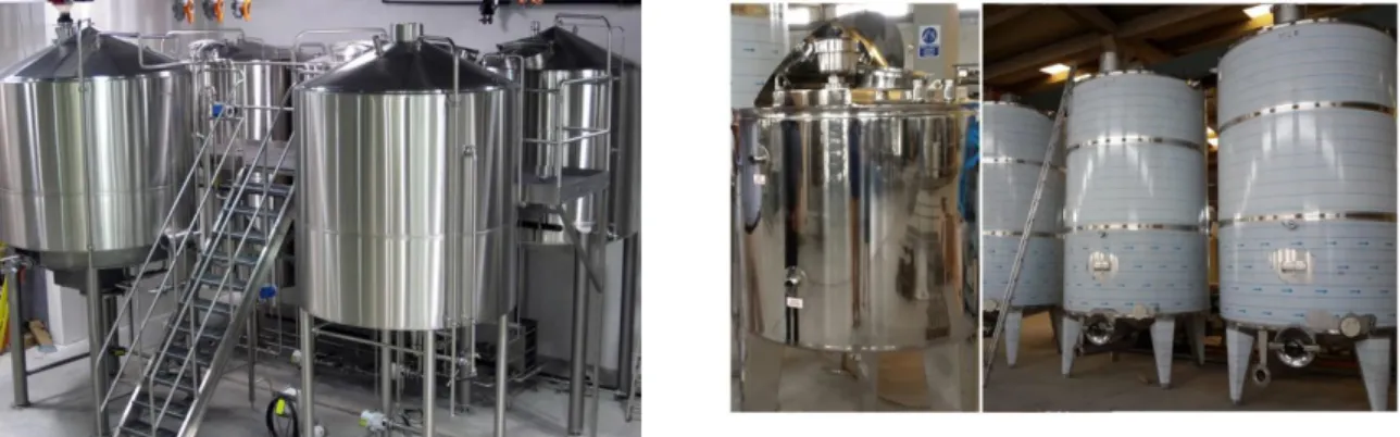
Figure 1-2: Two examples of products in the Terrofil catalog. ...5
Figure 1-3:Some examples of products made in the olive oil and beer industry. ...5
Figure 2-4: General procedure for a maceration process. ...7
Figure 2-5: Process of making tea. ...7
Figure 2-6: Percolation extraction process. ...8
Figure 2-7: Representation of a Hot continuous extraction process. ...9
Figure 2-8: Direct sonication using an ultrasonic horn (probe type). ...10
Figure 2-9: Indirect sonication using an ultrasonic bath. ...10
Figure 3-10: Representation of where the equipment will be installed. ...14
Figure 3-11: Front and side view of the final arrangement of the previously proposed extraction line.[13] ...15
Figure 3.12: Representation of the extraction line assembly in the ideal place.[13] ...15
Figure 3-13: Representation of the acrylic bowl holder and detail of the fixation to the bar.[13] ...16
Figure 3-14: Circuit diagram of the extraction line. (T1) Reservoir; (T2) Treatment vat 1; (T3) Treatment vat 2; (M1) mixer; (b1) pump; (V1) Solenoid Valve 1; (V2) Solenoid Valve 2 (V3) Solenoid Valve 3; (V4) Solenoid Valve 4. ...16
Figure 3-15: Route 1 scheme, ie recirculation. ...17
Figure 3-16: Route 2, ie only processing in treatment vat 2. ...17
Figure 3-17:Route 4, ie product processed in both treatment vats. ...18
Figure 3-18: Equipment base configuration, as well as the castors used. ...25
Figure 3-19: 3D modeling of reservoir 1, the body was placed transparent to visualize the inner angle. ...26
Figure 3-20: Front view and main dimensions of the main reservoir. ...27
Figure 3-21: Previously designed reservoir. ...28
Figure 3-22:Reformed reservoir. ...28
Figure 3-23: Exploded view of the main reservoir. ...28
Figure 3-24: 3D modeling of the lid used on the secondary reservoir. ...29
Figure 3-26: Redesigned circuit diagram: (R1) - Reservoir; (R2)- Reservoir; (C1)- Treatment vat; (C2)- Treatment vat; (B1)- Pump 1; (B2)-Pump 2; (EV1)- Solenoid Valve 1; (EV2)- Solenoid Valve 2; (EV3)- Solenoid Valve 3; (EV4)- Solenoid Valve 4; (VM1)- Hand valve 1; (VM2)- Hand Valve
2; ...30
Figure 3-27: Route 1, ie reservoir 1 recirculation. ...31
Figure 3-28: Route 2, that is, the product is processed only in treatment vat 1, directed to reservoir 2 and returned to reservoir 1. ...31
Figure 3-29: Route 3, that is, the product is processed in both treatment vats, directed to reservoir 2 and finally returned to reservoir 1. ...32
Figure 3-30: Route 4, that is, the product is processed in both treatment vats and collected after manual valve 2 is opened. ...32
Figure 3-31: First proposal even before the need to create a second deposit. ...33
Figure 3-32: Second proposal with the second reservoir already present. ...33
Figure 3-33: Third proposal, where the best position is sought for the pumps as well as the tank 2. ...34
Figure 3-34: Final 3D modeling of the equipment and its marked components. ...35
Figure 3-35: Image of the mixer supplied by the university. ...36
Figure 3-36: On the left, the main pump used in the equipment and on the right the pump supplied by the university. ...36
Figure 3-37: ODE® 21X4KT250 solenoid valve. ...36
Figure 3-38: Ultrasounds used in the extraction line. As you can see from the left image, the ultrasound base is flat while the right one is spherical. ...37
Figure 4-39: Bars (40x40mm) cut by chainsaw. ...39
Figure 4-40: Bars welded to form the rectangular base of the equipment. ...39
Figure 4-41: Process of cutting the pipes with the electric saw. ...40
Figure 4-42: Using the guillotine to cut the plate that will be the body of the reservoirs...40
Figure 4-43: Use of the calender to shape the previously cut sheet metal. ...41
Figure 4-44: Process of welding the reservoirs. ...41
Figure 4-45: Process of cutting the conical bottom of the reservoirs using a plasma gun. ...42
Figure 4-46: Use of a punch to form the conical bottom. ...42
Figure 4-47. Use of an impact device to make the conical bottom edge...43
Figure 4-49: Cut the holes where the bushings will be welded. ...44
Figure 4-50: Process of tapering the bottom of the treatment vats. ...44
Figure 4-51: Process of welding the conical bottom to the treatment vat. ...45
Figure 4-52: Process of welding the rings that make the connection between the treatment vat body and the cooling jacket. ...45
Figure 4-53: Flange welding that will make the connection between the tank and the tank cap. ...46
Figure 4-54: Upper flange welding. ...46
Figure 4-55: Initial assembly of the deposits in the respective base. ...47
Figure 4-56: Bending of the treatment vats supports. ...47
Figure 4-57: Assembly of the components, in the images on the right it´s possible to see the arrangement of the pumps. ...48
Figure 4-58: Photograph of equipment assembled and installed in the CVR building. Note that ultrasounds are also in place. ...49
Figure 4-59: Electrical equipment control system. ...50
Figure 4-60: On the left is a photograph of the inside of a clogged solenoid valve with silver skin. on the right the inside of pump 2 where it contained the o-ring. ...53
Figure 4-61: In the image on the right you can see the inside of a clogged solenoid valve with the silver skin and on the right the transfer pump used to replace the defective pump. ...54
Table List
Table 3-1: Pros and points to be improved on equipment. ...18
Table 3-2: Ideality matrix applied to equipment. ...20
Table 3-3: List of objectives ordered into sets. ...23
Table 4-4: Budget for equipment construction. ...52
List of Symbols Symbols Unit g Grama m Metro s Segundo W Watt Hz Herts L Litro °C Graus Celsios € Euro
List of Abreviations
CVR Centro para a Valorização de Residuos
TRIZ Teoriya Resheniya Izobreatatelskikh Zadatch
SA Sociedade Anónima
DHW Domestic Hot Water
MPI Inventive Principles Method
IPs SS UAE
Inventive Principles Stainless Steel
1. Introduction
In the scope of the course Dissertation of the Integrated Master Course in Mechanical Engineering of the University of Minho, it was proposed the manufacture and experimental validation of an ultrasonic extraction process.
In the early 21st century the demand for natural and "cleaner" extraction processes increased significantly, drawing attention to innovative and differentiated equipment from those used to extract synthetic dyes. One of the useful equipment in this field is the ultrasounds.
The main objective of this work is to manufacture and test equipment that uses ultrasound to extract caffeine from silver skin present in coffee beans.
Therefore, based on the work done by author Bruno Costa, the equipment was mechanically designed. Considering some possible improvements and some modifications imposed by the equipment manufacturer Terrofil SA, a possible model was presented. After its validation, the equipment was built.
Finally, already with the equipment installed in its intended location, a series of tests were performed in order to understand its real capabilities and working conditions.
1.1 Work Motivations
Some studies have shown that silver skin also contains caffeine. However, a recently published study showed compositional variability of extracts obtained from this by-product, depending on the extraction conditions.
At Bicafé, an average monthly production of 120 tonnes of roasted coffee produces about 1,120 kg of silver skin. At the end of one year, 13.44 tonnes of this by-product are discarded to date. Some of the known applications are composting / soil fertilization or combustion, by direct burning, for heating.
It is expected that the use of the new technology may contribute to an optimization of the extraction of chemical compounds. In this case, given the presence of caffeine in silver skin, it is intended to extract it in an efficient, faster and without using organic solvents, with a view to a possible later application in food products, cosmetics and body hygiene sectors.
1.2 Work Structure
This work is divided into five chapters. In this first chapter will be made a general introduction to the subject, introducing to the reader concepts such as extraction of dyes, whether natural or synthetic, and extraction via ultrasonic equipment. Also in this chapter, will be presented the motivations for the realization of this project, as well as its structure. Finally, a brief presentation will be given about the company with which the student worked throughout the equipment manufacturing and construction process.
In the second chapter, the state of the art and the theory of mechanical design will be presented. The first segment will include a brief explanation about the extraction of compounds by ultrasound technology, what types of compounds and equipment exist today. The second segment will focus on the application of the TRIZ method in the problems encountered, in order to simplify its solution.
In the third chapter, the equipment design will be presented. Will be analyzed the information from previous work, mostly technical drawings / 3D modeling and equipment requirements. Next, the solutions found will be presented, as well as the reformulation of the project. Finally, it will end with the presentation of the final project, ready for production.
In the fourth chapter, will be presented the whole equipment construction process by Terrofil SA and its validation already at CVR facilities. The construction will be divided into three phases, the structural part of the equipment (tanks and pipelines), the control part (pumps, solenoid valves and electrical panel) and finally the installation of ultrasound equipment. It will be presented the working conditions to which the equipment was subjected during the tests, as well as the results obtained and finally some problems found during these tests. In the fifth and last chapter, the main conclusions to be drawn from all the work done are presented. These conclusions will concern the structural part of the equipment as well as the control part. And finally, some future suggestions will be presented in order to improve the equipment.
1.3 Company Presentation
During the equipment manufacturing and construction process, the student had the opportunity to work in cooperation with Terrofil SA.
1.3.1 Location
The company is based in Barcelos, specifically in Silveiros. Founded in 1978 by Bernardino Terroso and later seconded by his sons Sérgio and Luís Terroso.
The location of the company is excellent, with proximity to highways (10km), freight ports (30 minutes from the port of Leixões and 40 minutes from the port of Viana de Castelo), as well as airports (30km from Porto airport and 100km from Vigo airport).
1.3.2 Main products and market applications
Terrofil has been dedicated since its inception to the production of agri-food equipments, having undergone several adaptations to the market demands over the three decades of existence, currently producing equipment for the following areas:
• Food production: Recognizing the great importance of the food industry in Portugal's economy, Terrofil has the technical and productive capacity to construct and develop equipment that meets your specific needs.
• Environment: Taking into consideration the environmental issues, Terrofil develops Industrial Wastewater Treatment systems for the most diverse areas of activity. The solutions developed are designed according to the needs of each client.
• Wine production: Transforming the fruit of the vineyard into a wine of excellent quality, means to carefully study the property of the grape to elaborate the treatment solution and adapt the necessary constructive typology. In a continually evolving sector, such as the oenological one, Terrofil offers cutting-edge products, always in balance with nature's fundamental process.
• Industry: Industry is a very important pillar in economic activity and as such has a plethora of opportunities for innovation as well as optimization of customized solutions for every situation. We build equipment for various purposes.
• Chemistry: The chemical industry is by nature highly competitive and highly rigorous. Terrofil uses specific steels considering their specific use of the equipment produced. In this context, in addition to the proper choice of steel, our welds are subjected to a special pickling and passivation process in order to preserve the physiological properties of stainless steel.
• Accumulators: Terrofil, being aware of the importance of domestic hot water storage solutions, has been developing heat accumulators for connection to solar thermal panels, heat pump or boiler.
Figure 1-2: Two examples of products in the Terrofil catalog.
1.3.3 Vision for the future
Terrofil's main objective is to expand its business to other areas, so as not to depend so much on the harvest season, as this is when its turnover is highest. Markets such as beer and olive oil production would be excellent for occupying the lowest production phase of the company.
2. State of Art
2.1 Solid-Liquid-Extraction
This is an expression used in various fields, be they medical or computer. In this work, the term "extraction" will refer to a separation process based on different solubilities. This process involves mass transfer and consists in which a compound present in a phase, liquid or solid, is transferred to an extraction solvent.
This process allows soluble components to be removed from solids. The mechanism of this process involves wetting the solid surface with the solvent, penetrating the solvent into the solid, dissolving the extractable particles, transporting the solutes from within the solid particles to their surface and dispersion of solutes within the volume of the solvent surrounding the solid particles diffusion and agitation. An example present in everyday life is the preparation of coffee. In this case water (solvent) is used to remove the coffee flavour from the coffee powder (extraction material).[1][2]
2.1.1. Maceration
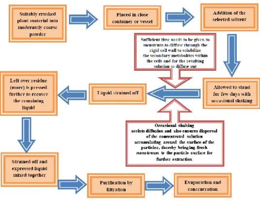
Maceration is a technique use in wine making and has been adopted and widely used in medicinal plants research. Maceration involved soaking plant materials (coarse or powdered) in a stoppered container with a solvent and allowed to stand at room temperature for a period of minimum 3 days with frequent agitation. The processed intended to soften and break the plant’s cell wall to release the soluble phytochemicals. After 3 days, the mixture is pressed or strained by filtration. In this conventional method, heat is transferred through convection and conduction and the choice of solvents will determine the type of compound extracted from the samples.
Maceration is preferably used with volatile or thermal instable products. It is “a cold” extraction of pulverized feed material in any solvent. In due course of time maceration became a popular and inexpensive way to get essential oils and bioactive compounds. For small scale extraction, maceration generally consists of several steps as shown below.[3]
Figure 2-4: General procedure for a maceration process.
2.1.2. Infusion
Fresh infusions are prepared by macerating the crude drug for a short period of time with cold or boiling water. These are dilute solutions of the readily soluble constituents of crude drugs, the most common example is the process of making tea.[4]
2.1.3. Percolation
This is the procedure used most frequently to extract active ingredients in the preparation of tinctures and fluid extracts. A percolator (a narrow, cone-shaped vessel open at both ends) is generally used (Figure 1). The solid ingredients are moistened with an appropriate amount of the specified menstruum and allowed to stand for approximately 4h in a well closed container, after which the mass is packed, and the top of the percolator is closed. Additional menstruum is added to form a shallow layer above the mass, and the mixture is allowed to macerate in the closed percolator for 24h. The outlet of the percolator then is opened, and the liquid contained therein is allowed to drip slowly. Additional menstruum is added as required, until the percolate measures about three-quarters of the required volume of the finished product. The marc is then pressed, and the expressed liquid is added to the percolate. Sufficient menstruum is added to produce the required volume, and the mixed liquid is clarified by filtration or by standing followed by decanting.[3]
Figure 2-6: Percolation extraction process.
2.1.2 Hot Continuous Extraction (Soxhlet)
In this method, the finely ground crude drug is placed in a porous bag or “thimble” made of strong filter paper, which is placed in chamber of the Soxhlet apparatus (Figure 2-7) The extracting solvent in flask is heated, and its vapours condense in condenser. The condensed extractant drips into the thimble containing the crude drug, and extracts it by contact. When the level of liquid in chamber rises to the top of siphon tube, the liquid contents of chamber siphon into flask. This process is continuous and is carried out until a drop of solvent from the siphon tube does not leave residue when evaporated. The advantage of this method,
compared to previously described methods, is that large amounts of drug can be extracted with a much smaller quantity of solvent. This effect tremendous economy in terms of time, energy and consequently financial inputs. At small scale, it is employed as a batch process only, but it becomes much more economical and viable when converted into a continuous extraction procedure on medium or large scale.
Figure 2-7: Representation of a Hot continuous extraction process.
2.1.3. Ultrasound assisted extraction (UAE)
The mechanic effect of acoustic cavitation from the ultrasound increases the surface contact between solvents and samples and permeability of cell walls. Physical and chemical properties of the materials subjected to ultrasound are altered and disrupt the plant cell wall; facilitating release of compounds and enhancing mass transport of the solvents into the plant cells. The procedure is simple and relatively low-cost technology that can be used in both small and larger scale of phytochemical extraction[5].
The ultrasonically assisted extraction is an inexpensive, simple and efficient alternative compared to conventional extraction techniques. The main advantages of ultrasound in solid– liquid extraction include the increase of extraction yield and faster kinetics. Ultrasonic extraction is a frequently used technique for the extraction of plant materials using liquid solvents and is proven for a fast and more complete extraction process in comparison with traditional methods because the surface area between the solid and liquid phase is significantly larger due to the cell disruption and particle dispersion. By the use of sonication also the operating temperature can be reduced, allowing the extraction of temperature-sensitive components. Compared with other novel extraction techniques such as
microwave-assisted extraction, the ultrasound apparatus is cheaper, and its operation is easier. Furthermore, the ultrasonically assisted extraction can be used with any solvent, such as the Soxhlet extraction, for extracting a wide variety of natural compounds.If necessary, explosion-proof systems for industrial process capacities are available. A substantial advantage of ultrasonics is the influence on the most important processing parameters: amplitude, time, temperature, pressure, and viscosity. Thereby, the extraction process can be optimized to ensure that the structure of the extracts does not become damaged. [6].
2.1.4 Ultrassonic Devices
An ultrasonic extractor will always consist of the following parts:
• A generator: This is an electronic or mechanical oscillator that needs to be rugged, robust, reliable and able to operate with and without load.
• A transducer: this is a device for converting mechanical or electrical energy into sound energy at ultrasonic frequencies.
Following are the two different types of ultrasound equipments which are commonly used in laboratory. The first one is the ultrasonic cleaning bath, which is commonly used for solid dispersion into solvent and for degassing solutions. The second one, the ultrasonic probe or horn system is much more powerful because the ultrasonic intensity is delivered on a small surface (only the tip of the probe) compared to the ultrasonic bath. This system of probe is widely used for sonication of small volumes of sample but special care has to be taken because of the fast rise of the temperature into the sample occurs.
Figure 2-8: Direct sonication using an ultrasonic horn
(probe type).
2.1.5 Advantages and Disadvantages of Ultrasonic Baths.
Although the cleaning bath is the piece of ultrasonic equipment most widely used by chemists, it is not necessarily the most effective. The advantages of using an ultrasonic bath are as follows:
• The ultrasonic bath is the most widely available laboratory source of ultrasonic radiation.
• Small cleaning baths are inexpensive.
• The acoustic field is evenly distributed throughout the bath liquid.
• No special adaptation of chemical apparatus is required. This allows conventional glassware to be used and facilitates the addition of chemicals, the use of high or low pressures or even an inert atmosphere during the operation.
On the other hand, the disadvantages of using an ultrasonic bath can be summarized as follows:
• The amount of power dissipated from the bath into the analytical system is usually not very large.
• The energy input must be assessed on an individual basis for each system as the amount of power delivered will depend on the bath size, the vessel type in batch steps or manifold type in continuous steps, wall thickness and bath position.
2.1.6 Advantages and Disadvantages of Ultrasonic Probes.
Probe devices undoubtedly provide the most efficient method for transmitting ultrasonic energy into an analytical process or step. The advantages of using an ultrasound probe for this purpose are as follows:
• The ultrasonic power delivered by a horn is directly related to the magnitude of vibration of the tip. Maximum powers of several 100 Watt per square centimeter can therefore be easily achieved.
• Ultrasonic streaming from the tip of the probe operated at moderate power is often sufficient to provide bulk mixing when dipped in the target system since energy losses during the transfer of ultrasound through the bath media and reaction vessel walls are eliminated.
• The probe can be tuned to give optimum performance (tuning here is the process whereby the entire probe assembly is brought into resonance with the transducer). On the other hand, disadvantages of ultrasound probes in this context include the following:
• Metal particles eroded from the tip can contaminate the system.
The high intensity of irradiation in the zone close to the tip may produce radical species potentially interfering with the normal course of the experiment [3].
2.3 The mechanical project theory
A growing proportion of companies are seeking to improve their product development processes as a way to increase competitiveness. In terms of product development, the need for competitiveness can be unfolded into the needs of reducing development time, increasing quality and reducing the cost of products in their life cycle. As a result of attempts to meet these demands, both business practice and product development research are receiving increasing attention. It is also noted that not only the product development area receives increasing attention, but the focus of research in the area shifts from the final stages of the development cycle (prototype building, testing, simulation and optimization) to early stages (product definition, product planning, conceptual design), where work takes place at higher levels of abstraction. [7-9]
2.3.1 Introduction to TRIZ
The term TRIZ has Russian origin (Teoriya Resheniya Izobreatatelskikh Zadatch) which means “Inventive Problem-Solving Theory”. This theory was developed by Genrich Saulovich Altshuller (1926-1998), Soviet Engineer and Researcher of the Russian Navy, who in 1946 he reviewed more than one and a half million patents from different areas. Through this analysis concluded that most of these patents were only system / product improvements already created and only a small percentage was something made of origin or somehow a invention. Altshuller also found that systems evolve to certain standards and not irregularly, from which he defined principles, tools and a theory for the troubleshooting, TRIZ.
He also found that over 90 percent of the problems engineers were facing had already been solved previously in another area, noting that many solutions can be derived from the existing knowledge in the company, industry or other industry. During investigations, Altshuller felt the necessity for the theory of creativity for the following conditions: [8]–[12]
• Being systematic.
• Taking the lead for the placing of the ideal solution in very wide solution space. • Being repeatable and reliable. However, not depending on the psychological tools • Reaching creative information.
3. Development of the Mechanical Project
After the method described in the previous chapter, it is important for the reader to realize that there is a work previously done by a colleague, which will be analyzed and reformulated in this chapter.
Before presenting the information from the work previously performed, it is important to mention some of the conditions imposed on the equipment.
Therefore, one of the most relevant conditions is where the extraction line will be installed. As mentioned above, the equipment will be installed in the CVR building, specifically in a space formed by an L-wall. With this condition, the size of the equipment was defined.
Figure 3-10: Representation of where the equipment will be installed.
As can be seen from the image above, the equipment must have a maximum of 800 mm in length and 1000 mm in width. The height of the equipment is not relevant since the room where it will be installed has very high walls, so it does not affect the design of the equipment.
Wall
Another limitation on the equipment was that the treatment vats were as unobstructed as possible, so that they could be easily accessed because of a maintenance issue and that the process could be filmed.
3.1 Prior Information
So, with all the conditions presented previously, the following provision for the equipment was proposed.
Figure 3-11: Front and side view of the final arrangement of the previously proposed extraction line.[13]
Figure 3.12: Representation of the extraction line assembly in the ideal place.[13]
Therefore, as can be seen from the above images, the treatment vats were placed facing the user and further back from the tank so that the process could be filmed. Regarding the electrical board, it was decided that it was important that it was facing forward and that a
base be built to put a computer. Finally, positioning the tank against the left wall was a purely aesthetic option.
The mounting of the vats in their supports was idealized by placing two bent plates, one higher and one lower, in the case of the stainless steel vat, while the acrylic vat will be supported by a bottom bent plate with a tube to serve as a guide and a bent plate on top divided in two allowing the tightening of the vat. These plates will be fixed to a bar by rivet nuts and bolts.
Figure 3-13: Representation of the acrylic bowl holder and detail of the fixation to the bar.[13]
Finally, in the idealized scheme, four solenoid valves, two pumps, a reservoir, two treatment vats and a mixer were present (see Figure 3-14).
Figure 3-14: Circuit diagram of the extraction line. (T1) Reservoir; (T2) Treatment vat 1; (T3) Treatment vat 2; (M1) mixer;
One of the initial conditions imposed on the equipment was that the system was flexible, that is, that allowed, with the same structure, several types of tests. As can be seen from the scheme of the previous chapter, the equipment was designed so that the product could make different routes. These are:
1- This route aims to recirculate the product, it exits from reservoir 1 and is pumped by pump 1 back to reservoir 1. In this case only the solenoid valve 1 is open.
Figure 3-15: Route 1 scheme, ie recirculation.
2- This route is if the user wants the product to be processed in the treatment vat 2 for a while without being pumped into the treatment vat 2. In this case only solenoid valve 2 is open.
3- In this route the product runs through both treatment tanks and is expelled for collection. In this case, solenoid valves 2,3 and 4 are open while solenoid valve 1 is closed.
Figure 3-17:Route 4, ie product processed in both treatment vats.
3.1.1 Advantages and disadvantages
Finally, we should analyze the strengths of the previous project and the points to be improved. As can be seen from Table 3-1 the strengths of the project are the need to design the treatment vats supports, as this process has already been done correctly and the same thing applies to the ultrasound sizing and equipment base. As negative points, the position of the elements will have to be rethought, as one of the requirements is that the treatment vats be placed in front to be able to observe the process correctly, finally the need to make the equipment more flexible (ie, increase the number of possible operations) is also a point for improvement.
Table 3-1: Pros and points to be improved on equipment.
Advantages Disadvantages
Treatment vats support already designed; Poor element positioning, especially treatment vats
Ultrasonic system already studied and optimized;
Need to optimize equipment to add more functions
3.2 Application of the Mechanical Project theory
In order to facilitate the reader's understanding, the equipment was divided into subsystems. For these subsystems, principles-based on methods of mechanical design theory have been applied to help the proliferation of ideas and solutions.
Thus, the development process can be divided into three main categories, the equipment structure, the ultrasound system and the electrical system and process control.
The structure will be divided into two subcategories, the base structure, the base on which all the equipment will be supported, as well as the wheels that allow the mobility of the equipment.
The ultrasound system will not have much relevance in this case because it was something already designed previously and no changes were made, either way some relevant topics will be presented.
The electrical system and process control will be divided into two subsystems, the electro valves and the electrical equipment that are part of the ultrasound system.
Development Structure Base structure Structure Elements Ultrassound System Control and electrical system Solenoid valves Ultrassound
3.2.1 Ideality Matrix
In this chapter only the ideality matrix will be used due to its greater proximity to the real problems encountered during the equipment redesign. That is, in the case of the ideality matrix, the parameters are chosen by the user according to the actual equipment problems The Ideality Matrix is very similar to the Contradiction Matrix, however, in this tool the parameters are arbitrated according to the user's need. That is, as a user the new equipment is intended to meet the following requirements:[14]–[17]
• Process versatility • Movable
• The most automated possible • Low production cost
• Ergonomic
Having the parameters defined, we proceed to the construction of the Ideality Matrix (that will indicate if they have a favorable, harmful or indifferent relation among themselves.
Table 3-2: Ideality matrix applied to equipment.
Parameters 1 2 3 4 5 1.Versatility + - + 2.Movable + 3. Automation + - 4. Production Cost - - 5. Ergonomic + +
The following justifications show why assigning a positive or negative sign to each row of the matrix:
I. Versatility:
Increased process versatility will imply a higher level of automation in the equipment, as can be seen from the presence of one more pump. Obviously, this will bring more options to the user to work with the equipment, therefore resulting in greater ergonomics in their work. The presence of more equipment and increased automation will, on the other hand, increase the cost of producing the equipment.
II. Movable:
The ability to be able to move the equipment is important for the user to be able to access any part of the equipment, either while operating or even maintaining it. Therefore, ergonomics is ultimately benefited.
III. Automation:
Increased automation will increase equipment versatility, meaning the user will be able to operate the equipment in different ways. This increased level of automation will require more electronic equipment, which will adversely affect the cost of production.
IV. Production Cost
The cost of production is obviously a very important parameter. In order for the equipment to be movable it was necessary to add four castors, this implied an increase in the production cost. Increasing the level of automation meant that an additional pump and the construction of another depot obviously increased the cost of producing the equipment.
The cost of production will increase as more components are added to the equipment. This happens if the mobility of the equipment is increased, as four casters have been added to make it possible to move it. The same thing goes for increasing the level of automation as you will need to add a pump.
V. Ergonomic
The ergonomics of the equipment is related to the "comfort" of use, therefore the possibility of being movable and the process options offered to the user give this ergonomics to the equipment.
Analyzing the Matrix, it remains to calculate the ideality level of the new packaging, which results from the following expression:
I𝑑𝑒𝑎𝑙𝑖𝑡𝑦 =
Σ(𝐵𝑒𝑛𝑒𝑓𝑖𝑐𝑖𝑎𝑙 𝐹𝑢𝑛𝑐𝑡𝑖𝑜𝑛𝑠) Σ(𝐻𝑎𝑟𝑚𝑓𝑢𝑙 𝐹𝑢𝑛𝑐𝑡𝑖𝑜𝑛𝑠+𝑐𝑜𝑠𝑡𝑠)=
6
4
= 1.5
(1)As can be seen the result is higher than 1, this means that the equipment has a good level of ideality.
3.2.2 Objective Tree
Next, in order to clarify some of the objectives, it was decided to build an objective tree. To do so, the following steps were followed:
1. The first step will be to form a list of goals to achieve: a. Safety b. Cost effectiveness c. Easy to repair d. Affordable e. Caffeine Extraction f. Mobile
g. High level of automation h. Ergonomic
i. Versatile
j. Easily accessible components k. Takes least possible space l. Safe for operator
2. Then sort these goals into their respective categories.
Table 3-3: List of objectives ordered into sets.
Ergonomic Cost effectiveness Efficiency Safe for operator Low maintenance Extraction of caffeine
Mobile Affordable Versatile
Takes least possible space Use of “used” equipment High level of automation Easily accessible components Extraction of caffeine
3. And finally, draw the objectives tree.
As can be seen from the objectives tree, three more basic concepts were expanded into several more specific objectives. This will help in equipment design and in solving possible problems.
Extraction Equipment
Efficiency
Versatile High level of
automation
Does the job Extraction of caffeine
Ergonomic
Safe for operator
Mobile Take least possible space Cost effectiveness Low maintenance
Affordable Use of "used" equipments
3.2.3 The manufacturing material
In food manufacturing, cleaning and sanitation are crucial. When it comes to equipment, it's important to know what materials to use and how selection can affect fabrication design and future care.
The properties of stainless steel play an important role in the design of various equipment. The use of high-quality SS in fabrication of processing equipment helps not only to prevent corrosion but also ensures purity of food product handled in that equipment. In addition to this, stainless steels are easy to clean and maintain and several different products can be manufactured in the same equipment. If properly utilized, equipment made of stainless steel can be expected to last for many years. On a life-cycle basis, the alloys are often the most cost-effective.
Manufacturers use a range of materials to store, convey and process food products. Metals offer exceptional strength properties necessary for high product volumes. But strength is not the only factor to consider. The best materials should be as non-corrosive and inert as possible.
The most common form of corrosion is oxidation, where oxygen reacts with a metal, usually in the presence of water, to produce a more non-reactive material such as rust. For ferrous metals, iron and steel, rust ruins surface quality and eventually structural stability. For other types of metals, however, oxidation is beneficial.
Stainless steel is used widely in food manufacturing, and for good reason. It is characterized by the addition of chromium — at least 10.5 percent of total composition. Chromium is highly reactive to oxygen environments and quickly forms a strong passivated barrier on its outer surface. This barrier is highly resilient and protects internal structures from further corrosion. The most common stainless-steel types are:
• 304 stainless steel: contains between 16 and 24 percent chromium, as well as alloys such as nickel, carbon and manganese. 304 stainless steel has excellent anti-corrosion properties, making it suitable for most food products. The presence of chlorides, however, can compromise passivated surfaces and cause pitting.
• 316 stainless steel: is like 304 stainless steel but with the addition of 2 to 3 percent molybdenum to increase resilience against chlorides, making it more suitable for meat products and foods with mild salt contents.
Both 304 and 316 stainless steels are austenitic, meaning they are extremely strong and easy to fabricate. Therefore, in the development of the project it was decided to manufacture the equipment in 316l stainless steel, the “l” stands for “low carbon”, these types of stainless steel is better for avoiding weld corrosion and good for high temperatures.
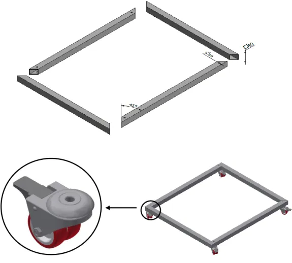
3.2.4 Base Structure
The base on which all the equipment will be laid will consist of four square bars made of AISI316l stainless steel (as well as all components used in the equipment). The bars are cut at 45° at both ends for ease of assembly. All bars will be drilled with hole M10 to allow the coupling of the four castors, these have rotating support with brake, which allows total freedom of movement to the equipment.
3.2.5 Main Reservoir
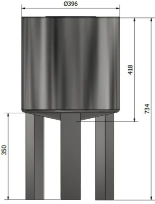
Although well designed and modeled, the previous project was not optimized for production. It was necessary to design some essential elements for the assembly of the equipment, as well as the creation of an angle to fix the lid of the reservoirs to them, a conical bottom for the deposits so that the product drains properly and finally moved the legs for rectangular bars for standardization reasons and easy purchase in the market.
Figure 3-19: 3D modeling of reservoir 1, the body was placed transparent to visualize the inner angle.
The previously designed reservoir did not include these connecting components such as the angle (which connects the lid and the reservoir body) and the flange (which connects the mixer and the reservoir lid). All the components are properly drilled to allow conection to each other. Finnally, the tank is supported by 3 rectangular legs with a height of 350mm. Initially the target volume was about 50L, so the deposit volume will be calculated after the changes. To calculate the volume, the deposit will be divided into two bodies, the cylindrical main body and the frustoconical bottom.
𝐶𝑦𝑙𝑖𝑛𝑑𝑒𝑟 𝑉𝑜𝑙𝑢𝑚𝑒 = 𝜋 × 𝑟2× ℎ = 𝜋 × 198 × 370 = 4.55 × 10⁷𝑚𝑚3 = 45.5 𝐿 (3.1) Being: 𝑟 = 𝑅𝑎𝑑𝑖𝑢𝑠 ℎ = 𝐻𝑒𝑖𝑔ℎ𝑡
𝐹𝑟𝑢𝑠𝑡𝑜𝑐𝑜𝑛𝑖𝑐𝑎𝑙 𝑉𝑜𝑙𝑢𝑚𝑒 =𝜋ℎ 3 × [𝑟𝑀 2 + 𝑟 𝑀× 𝑟𝑚+ 𝑟𝑚2] = 𝜋 × 50 3 × [196 2+ 196 × 33.4 + 33.42] = 2.2 × 106 = 2.2 𝐿 (3.2) Being: 𝑟𝑀 = 𝐵𝑖𝑔𝑔𝑒𝑟 𝑏𝑎𝑠𝑒 𝑟𝑎𝑑𝑖𝑢𝑠𝑠 (𝑚𝑚) 𝑟𝑚 = 𝑆𝑚𝑎𝑙𝑙𝑒𝑟 𝑏𝑎𝑠𝑒 𝑟𝑎𝑑𝑖𝑢𝑠 (𝑚𝑚)
Therefore, summing the two volumes yields about 48L, that is, a value very close to the initially desired value. This slightly lower figure is related to some measures imposed by the company when constructing the frustoconical bottom.
Figure 3-20: Front view and main dimensions of the main reservoir.
As can be seen from the images bellow, in the reformed reservoir there are holes to fit the mixer, as well as a flange to fix it non-permanently. It is also possible to observe the holes that allows the lid to be fixed to the inner corner, which allows the lid to be removed if cleaning is necessary inside the reservoir.
Figure 3-23: Exploded view of the main reservoir.
3.2.6 Secondary Reservoir
The second reservoir has the function of housing the mixture for some time until it is extracted or sent back to the deposit 1. Therefore, the requirements for this deposit were:
• Be smaller than reservoir 1;
• Be accessible inside if you need to wash it.
Figure 3-21: Previously designed reservoir. Figure 3-22:Reformed reservoir.
Bushing inlet Legs Conical Bottom Body Inner Corner Lit Flange
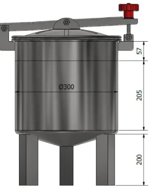
This tank has a configuration similar to the tank 1 configuration, namely a cylindrical body, a frustoconical bottom, three square legs of 40 mm and 200mm height. This reservoir has a lid coupled for the user to have access to it, additionally inside the lid was placed a sealing rubber. Finally, two side holes were designed to connect the pipes.
Figure 3-24: 3D modeling of the lid used on the secondary reservoir.
Therefore, to calculate the deposit volume 2, the same equations were used to calculate the reservoir volume 1.
𝐶𝑦𝑙𝑖𝑛𝑑𝑒𝑟 𝑉𝑜𝑙𝑢𝑚𝑒 = 1.85 × 107 = 18.5𝐿 𝐹𝑟𝑢𝑠𝑡𝑜𝑐𝑜𝑛𝑛𝑖𝑐𝑎𝑙 𝐵𝑜𝑡𝑡𝑜𝑚 = 1.3 × 106 = 1.3𝐿
𝑇𝑜𝑡𝑎𝑙 𝑉𝑜𝑙𝑢𝑚𝑒 = 18.5 + 1.3 ≅ 20𝐿
Figure 3-25: Front view and main dimensions of the secondary reservoir.
In conclusion, the volume obtained is 20L, which is an acceptable value that meets what was intended.
3.2.7 Control and Eletrical System
After some analysis of the possible routes presented earlier, it was possible to improve some of these routes and add others.
• On route 1 we chose not to change anything because of its simplicity.
• Regarding route 2, it would be interesting to have the possibility of collecting the processed product only in treatment vat 2.
• Regarding route 3, it was considered that the processed product could be recirculated to reservoir 1. The same idea was then applied to route 2, ie the possibility of recirculating the processed product only in the treatment vat 2 for the reservoir 1. For this to happen, it was necessary to design a second reservoir and a second pump.
Figure 3-26: Redesigned circuit diagram: (R1) - Reservoir; (R2)- Reservoir; (C1)- Treatment vat; (C2)- Treatment vat; (B1)-
Pump 1; (B2)-Pump 2; (EV1)- Solenoid Valve 1; (EV2)- Solenoid Valve 2; (EV3)- Solenoid Valve 3; (EV4)- Solenoid Valve 4; (VM1)- Hand valve 1; (VM2)- Hand Valve 2;
As can be seen from the above scheme, some routes have been added to complete the previously idealized circuit, such as:
1. As stated above, this route aims at the direct recirculation of the product, ie it leaves the reservoir 1 and is pumped back to it. In this case only the solenoid valve 1 is open.
Figure 3-27: Route 1, ie reservoir 1 recirculation.
2. In this route the product is pumped into the treatment vat 1 and then processed there. After treatment the solenoid valve 4 is opened and the product goes to reservoir 2 and then pumped back to reservoir 1. In this case only solenoid valve 2 and 4 are open.
Figure 3-28: Route 2, that is, the product is processed only in treatment vat 1, directed to reservoir 2 and returned to
reservoir 1.
3. In this route the product is pumped into the treatment vat 1, when this one is full, the product will go to the treatment vat 2. In this case, both treatment vats can process the product if the user wishes it. When the process is complete, the user will open the hand valve 1 so that the product is directed to the reservoir 2 and finally pumped back to the reservoir 1.
Figure 3-29: Route 3, that is, the product is processed in both treatment vats, directed to reservoir 2 and finally returned to
reservoir 1.
4. In this route, as in the previous one, the product is pumped to the treatment vat 1 and, after it is full, directed to the treatment vat 2. Finally, the user will open the hand valve 2 to collect the processed product.
Figure 3-30: Route 4, that is, the product is processed in both treatment vats and collected after manual valve 2 is opened.
Regarding the pipes, the existing constraints were that the pipping system did not impede the visibility of the treatment vats, so the pipes were placed under and behind the components. The proposal below predates the decision to create a second deposit. This design had as its main function to understand the position of the second pump.
Figure 3-31: First proposal even before the need to create a second deposit.
In the following proposal, the second deposit is already present and the position of the pumps has been changed again.
In this case, as in the previous one, the position of the treatment tanks so far behind did not please. Visually it was also not pleasant that the bombs were so far apart.
In the following proposal it was decided to put the two pumps in front, but again the treatment vats are too far behind. The positioning of the reservoir 2 in front of the reservoir 1 is not ideal either.
Figure 3-33: Third proposal, where the best position is sought for the pumps as well as the tank 2.
Finally, the following proposal was chosen. As you can see in the picture, the tank 2 is placed behind the treatment vats (if you need to access it, you can move the equipment as it has wheels), the pumps placed side by side (aesthetically much nicer) and the treatment tanks well ahead completely clear of the pipes.
Figure 3-34: Final 3D modeling of the equipment and its marked components.
Being
1. Main reservoir 2. Secondary reservoir 3. Acrylic Treatment vat
4. Stainless steel treatment vat 5. Treatment vat support 6. Eletrical Box
The mixer used was supplied by the university, Italvalvole® IMF series has a power of 0.33 HP and a propeller diameter of 120 mm. To view your datasheet, see Annex 3- Mixer Technical Sheet.
Figure 3-35: Image of the mixer supplied by the university.
For pump 1, Italvalvole's IPAD 2 pump was selected, while pump 2 was supplied by the university in order to reduce costs.
Figure 3-36: On the left, the main pump used in the equipment and on the right the pump supplied by the university.
For solenoid valves, the ODE® 21X4KT250 solenoid valves were selected. The data sheet is present in the Annex 4- Solenoid Valve Technical Data Sheet.
3.2.8 Ultrassound System
To conclude, the ultrasound equipment consists of: ultrasound generator, acoustic transducer, wave / booster precursor, acoustic radiator and equipment fixing flange to the treatment chamber. The ultrasound generator and acoustic transducer are standard, but the remaining elements should be optimized, considering the conditions of the environment, for the extraction process to be as cost effective as possible.
The operation of ultrasound technology consists of the transformation of electrical energy, which is provided by a wave generator, into high frequency mechanical impulses caused by the displacement of piezoelectric material in the transducers which together with the wave precursor and acoustic radiator (with optimized design to increase mixing and extraction efficiency) transfers the pulses to the aqueous medium. Therefore, the ultrasound system is capable of creating an acoustic field capable of inducing in the aqueous medium a pressure field sufficiently high to cause sufficient cavitation and acoustic beams to promote aqueous mixing and homogenization and caffeine extraction from the silver skin coffee bean. Theoretically, it is established that when there is an acoustic intensity greater than 2 𝑊𝑐𝑚2⁄ generated by the mechanical impulses induced in the aqueous medium, the cavitation phenomena and acoustic fluxes promote the possibility of mass transfer.
The extraction process used in this line allows an efficient extraction from the use of an ultrasound cell, composed by two acoustic transducers, one of mixing and extraction characteristics and the other of extraction / homogenization characteristics, duly optimized. The transducers work independently in a frequency range between 19-21 kHz. The combination of the effects of the two transducers promotes caffeine extraction with maximum yield [13].
4. Manufacture and Assembly
The construction of the equipment was done at Terrofil, so that the purchase of most of the materials was their responsibility. Note that the second pump, ultrasound and mixer were supplied by the university. Finally, it should be noted that all equipment frame material is made of stainless steel AISI 316l.
4.1 Construction
The construction of the equipment will be divided into two phases: the structure and the electric control.
The manufacture of the equipment came mainly from three types of raw materials: • Steel plate: Reservoirs and treatment vats.
• Steel bars and steel tubes: Base structure, piping and brackets. The main technologies involved in manufacturing were:
• Calendering
• Sheet metal cutting • Welding
• Electric sawing • Puncture • Machining
4.1.1 Structure
The construction of the entire structure lasted about 5 days, this procedure was done by only one worker. Below, the procedure will be enumerated:
• Cut the bar (40x40mm) for the outer structure where the equipment will be laid;
Figure 4-39: Bars (40x40mm) cut by chainsaw.
• Weld the bars to form the outer structure;
• Cut pipe to make the body of the treatment tank, as well as for the cooling jacket with the electric saw;
Figure 4-41: Process of cutting the pipes with the electric saw.
• Cut the plate in the guillotine to make the body of both deposits;
• Wind the previously cut sheet by calendering.
Figure 4-43: Use of the calender to shape the previously cut sheet metal.
• Weld the reservoirs;
• Cut the plate to make the conical bottom of the deposits (plasma)
Figure 4-45: Process of cutting the conical bottom of the reservoirs using a plasma gun.
• Use of a punch to shape the conical shape of the bottom;
• Make the "edge" of the bottom with impact device;
Figure 4-47. Use of an impact device to make the conical bottom edge.
• Cut the holes to position the bushings in the treatment tanks;
Figure 4-49: Cut the holes where the bushings will be welded.
• Conically form the bottom of the treatment vat with a hammer;
• Weld the conical bottom to the body;
Figure 4-51: Process of welding the conical bottom to the treatment vat.
• Weld the rings that make the union between the tank and the cooling jacket.
• Weld the inner flange that will make the connection between the tank and the lid. Therefore, allowing it to be removable.
Figure 4-53: Flange welding that will make the connection between the tank and the tank cap.
• Weld the flange that will make the connection between the tank system and the ultrasound;
• Mounting the reservoirs to the structure;
Figure 4-55: Initial assembly of the deposits in the respective base.
• Next, bend the treatment vats holders;
• Finally, the treatment vats were placed in the proper places already supported by the bent plates, the pumps were fixed, and the pipes were assembled.
Figure 4-57: Assembly of the components, in the images on the right it´s possible to see the arrangement of the pumps.
As stated above, various parts such as the connecting rings between the treatment vats and the cooling jacket, the flanges and the holders of the same vats were designed to be laser cut. Of course, throughout this process there are small operations that have not been mentioned here as they are not crucial to the construction, such as deburring the welds to make the process more aesthetically pleasing.
4.1.2 Command control
The control of the system is carried out by an electrical panel, here you can turn on and off the mixer, both pumps and the four solenoid valves. In addition, the electric panel contains two speed variators, one for the mixer and one for pump 1 (see annex 6).
Figure 4-59: Electrical equipment control system.
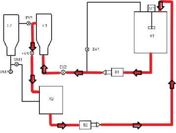
As already mentioned, the flow control of the product is made by four solenoid valves, which allow to choose the extraction form that the user wants.
As mentioned above, the use of solenoid valves allows several possible paths for the product, in the image below you can see these possible paths.
I. Route 1: This route aims at the direct recirculation of the product, it leaves the reservoir 1 and is pumped back to it. In this case only the solenoid valve 1 is open. II. Route 2: That is, the product is processed only in treatment vat 1, directed to
reservoir 2 and returned to reservoir 1.
III. Route 3 and 4: In this route the product is pumped into the treatment vat 1, when this one is full, the product will go to the treatment vat 2. In this case, both treatment vats can process the product if the user wishes it. When the process is complete, the user will open the hand valve 1 so that the product is directed to the reservoir 2 and finally pumped back to the reservoir 1 or to be drained out.
Being,
• Red line: Route 2 • Blue line: Route 3 and 4 • Green line: Route 1
4.2 Construction Cost
After construction it is possible to get the price of the whole process. Please note that this budget includes labor and adjacent cost to Terrofil's construction of the equipment.
Table 4-4: Budget for equipment construction.
Component/Designation Amount Unit Cost [€] Total Cost [€]
Solenoid Valves 4 265 1060 Pump 1 640 640 Electric Board 1 2340 2340 Door Ø 300 1 100 100 Acrylic Vat 1 1000 1000 Proof Tap 1 50 50 Casters 4 45 180 Junctions 1” 13 15.89 206
Stainless Steel AISI 316 Art.2039 thread 1”
Ferrule 24 2.9 70
Stainless Steel Reduction AISI 316 114.3x48.3mm 45.3 45.3
Machined Flange 1 209 209
Assembly and labor cost - - 3099
Ultrasound System 2 10325 20650

![Figure 3.12: Representation of the extraction line assembly in the ideal place.[13]](https://thumb-eu.123doks.com/thumbv2/123dok_br/17227563.786845/32.892.310.636.677.969/figure-representation-extraction-line-assembly-ideal-place.webp)