Introduction
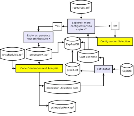
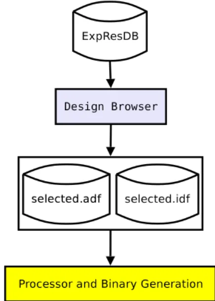
Codesign Environment Supporting Processor Customization
Transport Triggered Architectures
In line 5, the result of the addition is read from the output operand back into register r3. The result of the comparison is transferred to a boolean register, which is used in the conditional execution on the next line.
TTA-Based Codesign Environment
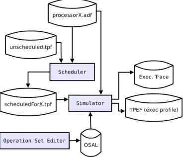
Profiling data consists of the number of times each instruction is issued in the simulated program. Therefore, one of the main requirements placed on the Simulator is high speed of simulation of parallel code. Activated operations and the operation latency are simulated in the second part of the simulation.
It is clear that the function, i.e. the behavior of the operation, the most important characteristic of the operation as seen by the programmer.

Requirements
Retargetability
The TCE Simulator should be able to simulate any TTA with any user-defined operating set type, without requiring the recompilation of the toolset. Given the simplicity of the architecture, simulating a TTA processor is not a complicated task as such. The resources of the simulated TTA processors are fully user-defined within the limits defined by TCE's TTA model.
Sequential programs that are not scheduled for any target processor must also be supported by the simulator.
Accuracy
The instruction cycle, in the case of TTA, is usually the length of a processor clock cycle. Since only the details that are visible to the programmer need to be simulated, a higher-level abstraction of the simulated program can be used instead. Furthermore, the contents of instruction memory are usually not accessible to the executed program itself.
Finally, since the encoding of the instructions can be fully defined by users, it is possible to produce several different binary representations of the same program.
Simulation Statistics and Traces
This level of detail is beyond the scope of the TCE simulator, especially since deadlock cycles are invisible to the program and visible only as additional clock cycles. Currently, the research algorithm does not use utilization data directly, but only through the results of the cost estimator. The bus trace lists the data contained in each machine bus in each simulated instruction cycle.
Execution time of simulated programs is one of the most interesting statistics from the simulator.
High Parallel Program Simulation Speed
Designs can be verified by comparing the bus trace generated by the TCE simulator to the bus trace generated by the HDL simulator. Execution time is the number of clock cycles required to execute a given program with given inputs. This data can be used to identify program "hot spots" so that optimization efforts can be focused on the parts of the program that benefit the most from optimization.
Program Debugging Capabilities
Connection to Hardware Simulation
In compiled simulation, the simulated instructions are translated into the native processor instructions of the simulation environment. The preprocessing of the simulated program model can be viewed analogously to the translation of instructions in the compiled simulation paradigm. To make the simulation as efficient as possible, only the properties of the processor visible to the programmer are modeled.
Before calling the advanceClock() function units, the memory model is signaled about the progress of the instruction cycle.
Operational Principles
Data Transport Simulation
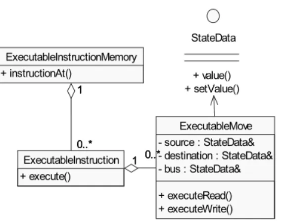
The simulation of the transports described by the TTA instruction can be reduced to a loop that copies data from parts of the source processor to buses and to parts of the destination processor as described at each instruction shift. In contrast, simulating data transfers with preprocessed instructions is straightforward, as all instruction processing is done before execution, and the write side effects are hidden within the class that models the target processor part (see Section 5.6 for details). For each transport, data is copied from source to bus and from bus to destination.
If the move has a guard expression and evaluates to false, the copy from the bus to the destination is ignored.
Processor State Simulation
Real time was used instead of CPU time because it gives a more realistic view of the speed, as it is the time perceived by users of Simulator. The version of the program used in the test was modified to be suitable for platforms without a 64-bit integer type. Due to the fact that sequential simulation speed is less critical than parallel simulation speed (see Section 3.4), the optimization effort is focused on parallel simulation.
The effectiveness of the simulation was benchmarked by timing the simulation times of the test programs.
Implementation
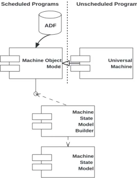
Processor Model
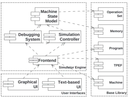
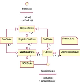
From the point of view of the simulated program, MSM looks like a set of machine parts that can be read from or written to. The machine state elements that enable reading and writing implement an interface called StateData. The parts of the simulated machine that need to operate when the simulated instruction cycle is advanced implement an interface called ClockedState.
The endClock() method signals to the function unit model that all transports of the instruction are simulated, which means that the data of the transports is written to its input port.
Program Model
Simulation Controller
The Breakpoint Manager module of the Debug System listens for new instruction execution events and stops the simulation before an instruction that has a set of breakpoints is executed. Runtime errors of the simulated program, such as a write to a memory location outside the bounds of the address space, are also reported as simulation events. These event handlers inform the user of the reason for the execution error, thus providing valuable information for debugging the simulated program.
Finally, the user interfaces of the Simulator can use the event handling mechanism to update their views when there is a change in simulation state, as indicated by the model-view-controller architecture [19].
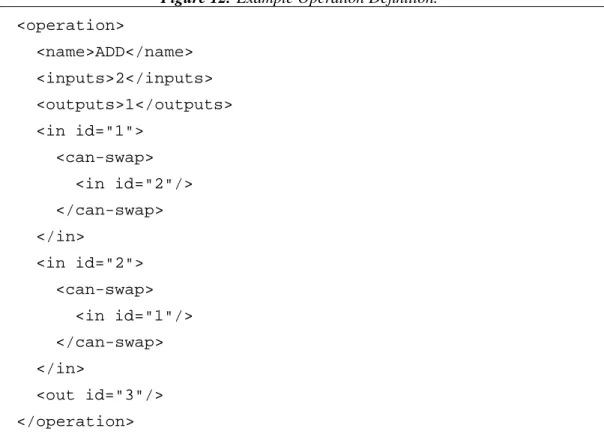
Operation Set Abstraction Layer
This set of macros is often called "operation behavior description language", even though it is only camouflage whose purpose is to hide the implementation of the behavior definition plug-in interface from TCE users. 14 used the macros to describe the behavior of operation ADD of the base operation set. In the example description of ADD operation, the first and second operands are treated as integers, summed, and the result of the summation is written to the third integer operand, which is an output operand.
The RETURN_READY statement simply signals the Simulator that all the results of the operation have been calculated.
Modeling Data Memory
The simulator uses a default Memory Model implementation called IdealSRAM for simulating data memory access in parallel simulation and an optimized implementation called SequentialMemory for sequential simulation. Clearly, no practical memory is capable of serving unlimited concurrent accesses, so such a memory model is overly optimistic. It is still safe to use an ideal memory model for program simulation since deadlock cycles caused by conflicting memory accesses are invisible to the simulated program.
The disadvantage of using a less accurate memory model is that the tracing cycles are not counted.

Simulation of Instruction Cycle
The function returns true if the last instruction of the first executed procedure was executed. In this test case, no additional code was inserted into the test program to produce output data for verification purposes, but the correctness of the simulation was verified using the debugging capabilities of the TCE Simulator. For example, a model implementation could simulate a cache by storing access history in a data structure similar to that of an actual hardware cache.
The code from the dynamic library will be used in place of the current simulation code.

Verification and Benchmarking
Sequential Simulation
According to the CHANGELOG file included in the modified Tremor distribution, the changes were made by J.A. Bezemer, the test program implemented and used a version of the dynamic memory allocation function malloc() that does not require operating system support. The input file was converted to a C char array which was concatenated in the test program.
The only input is cast to a char and written to the output stream stored in the state instance (referred to as STATE).

Parallel Simulation
For example, the simulation of addressable data memory units of arbitrary width is completely unnecessary in the case of sequential simulation, because the widths of the units used (minimum addressable unit an 8-bit byte, natural word an integer 32 -bit) are the same as in most current desktop processors. TCE Simulator can be converted to use the compiled simulation technique by replacing the Simulation Controller implementation with one that delegates the implementation of the simulation loop to the compiled program. The Simulator's architecture and design is highly modular and follows object-oriented design principles.
The state of the processor is maintained in an optimized object model, which avoids unnecessary simulation of inactive parts of the processor.
Future Extensions
Parallel Computation
In order to use multiple processors, existing programs may need to be modified to perform calculations in parallel, on multiple threads of execution. TCE Simulator is simulating a highly parallel processor architecture, so the simulation code is suitable for parallelization. Due to the independent functional units of TTA, it is possible to split the simulation of different functional units into multiple threads of execution.
The protocol for communicating with the simulation server may include commands for starting a new simulation and retrieving simulation results.
Computing Lock Cycles Generated by Control Unit
Connection to Hardware Simulation
Communication between the rest of the simulated system and the TTA simulated processor can be done by implementing a new memory model for the TCE Simulator. In the event that communication via a special operation is required, the OSAL operating model used to simulate the special operation would include code that uses a C to VHDL interface to communicate with the simulated system. The only required input to the TCE simulator from the system simulator would be the clock signal.
When the TCE simulator detects that the clock signal has changed, it simply executes the code that simulates a clock cycle.
Compiled Simulation
Simulator's accuracy is at the instruction cycle level and only the architecture of the TTA processor is simulated, i.e. Simulator only models the details that are visible to the programmer. In addition, the TTA concept was mainly described from the programmer's point of view, which is enough to understand the design of the Simulator. The design and implementation of the most important parts of the Simulator were described in more detail, less important details were left to a separate design document.
Source, destination and bus of the move are resolved, that is, corresponding state objects are found from the object model that maintains the simulation state of the processor.
Conclusions
Bibliography