In the first part of the dissertation, we present an extensive mathematical model to describe the packet scheduling of the data flow graph. We optimize the performance of the software switch by improving the packet scheduling and embedding of the dataflow-graph software switch.
Background
In this thesis we focus on the main data level components: the software switches. All of these software switches use both the dataflow graph abstraction and the DPDK library, but each has unique features.
Research Goals
For example, the robot motion control use case's delay-SLO requirement specifies latency requirements on a motion control traffic flow in the software switch's data flow graph. High-availability applications such as robot motion control or voice on a mobile gateway require the software switch to function safely even when a CP U error or software error occurs.
Dissertation Structure
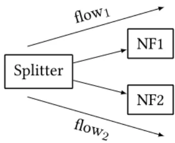
There are two major scheduling modes used in data flow graph processing that focus on efficiency and rate-proportional fairness: explicit scheduling and run-to-completion execution. In run-to-completion execution, the entire input batch is traced at once by the data flow graph, automatically by upstream modules.
Problem Formulation
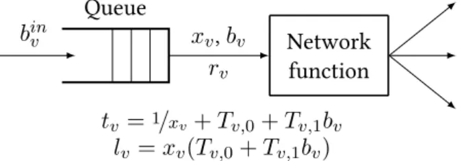
For ak-way splitter, the cost of an unbuffered execution overbatches including kpackets each would be 2k2, which buffering would reduce tok+k2; this gives approx. 2× batch processing gain at the expense of k×queue delay. We tackle two inherent deficiencies in high-speed packet processing reality: the lack of a sufficient abstraction to control module execution order in a run-to-completion dataflow graph, and the difficulty of controlling modules' queue backlogs in a way that processing occurs in as large batches as possible while each service chain receives enough resources to meet the SLO.
New Results
- Quantifying Batch-processing Gain
- System Model
- Optimal Explicit Data-Flow-Graph Batch-scheduling
- Optimal Run-To-Completion Data-Flow-Graph Batch-scheduling . 25
The optimal run-to-completion data-flow-graph batch scheduling problem is polynomial traceable and the optimal run-to-completion batch schedule is unique and well-defined. The optimal data-flow graph batch scheduling can be expressed in our model for both explicit and run-to-completion scheduling.
![Figure 2.4: Service-time Profile: Execution time [nsec] for different modules as the function of the input batch size, averaged over 10 runs at 100, 000 batches per second](https://thumb-eu.123doks.com/thumbv2/9dokorg/2497522.294290/25.892.202.676.199.522/figure-service-profile-execution-different-modules-function-averaged.webp)
Related Work
To our knowledge, this is the first time an equivalence between the two crucial data flow graph planning models has been shown. Note, however, that the assumptions are important to maintain equivalence; in particular, WFQ scheduling allows for lossy operation (if a module is not scheduled often enough to keep the backlog bounded, the input queue will overflow, leading to packet loss), while an RTC schedule is lossless in nature (we believe this is not actually a limitation, but an important feature for RTC); our result is the first to point to the equivalence between these two popular data flow graph planning modes. SDFGs) in which nodes represent processing components are arcs describing the control flow, implemented as FIFO queues. To allow implementation of more complex programs, the SDFG model was further generalized to cyclostatic data flow graphs [69] and dynamic data flow graphs [70] that allow for dynamic behaviors such as conditional branching and dynamic scheduling.
With these generalizations, dynamic data flow graphs tend to be used in DSP, stream/media processing [71], and machine learning [38]. Unlike our model presented in this chapter, this discrete model focuses only on the input queue, and therefore does not cover the details of batch scheduling of the software switch data flow graph.
Summary
To this end, we present a one-stage rolling horizon controller to implement optimal packet scheduling with SLO delay in a run-to-completion model. Next, we show the implementation of partial buffers in detail; the optimal packet scheduling of the data flow graph from execution to completion is based on the control of triggers on the input queues of the modules (see Section 2.3.5). Similarly, the open problem we tackle is the enforcement of latency SLOs in the run-to-completion data flow graph schedule.
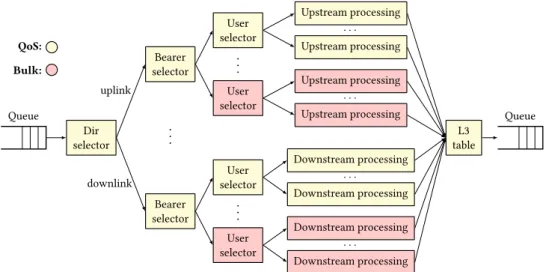
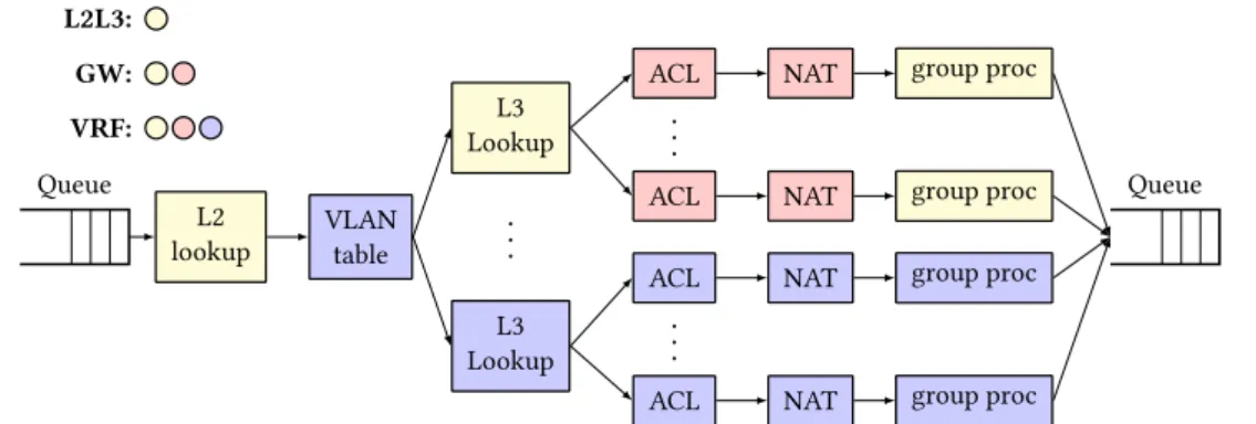
To model different use cases of L2/L3 (virtual) routing, we present the following data flow diagrams (see Figure 3.3): the L2/L3(n) pipeline implements a basic IP router, with L2 lookup, L3 longest prefix matching, and batch processing for next-hops; the GW(n) use case extends this pipeline to a full gateway with NAT and ACL processing for nnext-hop groups; and the VRF(m,n) pipeline implements virtual GW(n) instances preceded by an incoming VLAN separator. This enables us to move forward: implement performance guarantees such as Latency SLOs as well as optimize the scheduling performance of data flow graph sets.
Problem Formulation
New Results
- Fractional Buffer
- Inserting/Short-circuiting Buffers
- Feasibility-Recovery Method
- Pipeline Decomposition
- On-Off Control Algorithm
- Integration with BESS
- Evaluation
For this, you need to identify flowsf that may violate delay-SLO:t˜f ≥(1−δ)Df. The figure shows for each control period the value of the trigger at the ACL module in the upper branch (first VRF, first next hop), the total delay and delay-SLO of the flow delivered in the upper branch, and the normalized cumulative packet rate with the Null, Max and Projected Gradient algorithms. Meanwhile, when there is room to perform batch defragmentation, the controller quickly reaches the efficiency of the Max algorithm and delivers 2-3× the total throughput of the Null algorithm (note the log scale on Figure 3.7a/Rate).
The rest of the users generate bulk traffic at bearer-1 with no delay SLO set. It is easily the complexity of the underlying data flow graph that fundamentally determines the performance of the controller.
Related Work
Galleon adaptively controls the number of batches to process at a single poll to satisfy SLOs, while minimizing context switch overhead from the container environment of the NF runtime, and supports latency-SLO-sensitive scaling of NF chain instances. Contrary to our controller framework that works on common hardware, these works are bound to given NFV environment: they need a certain CP U feature, or a specific underlying network topology. Moreover, our controller framework extends previous work by providing a unique combination of dynamic internal batch defragmentation instead of applying clustering only to packet I/O, analytical techniques for controlling queue backlogs using a new abstraction, fractional buffers, and selective SLO enforcement against the granularity of individual flows that expands batch-sensitive traffic with bulk-flow-sensitive traffic.
Summary
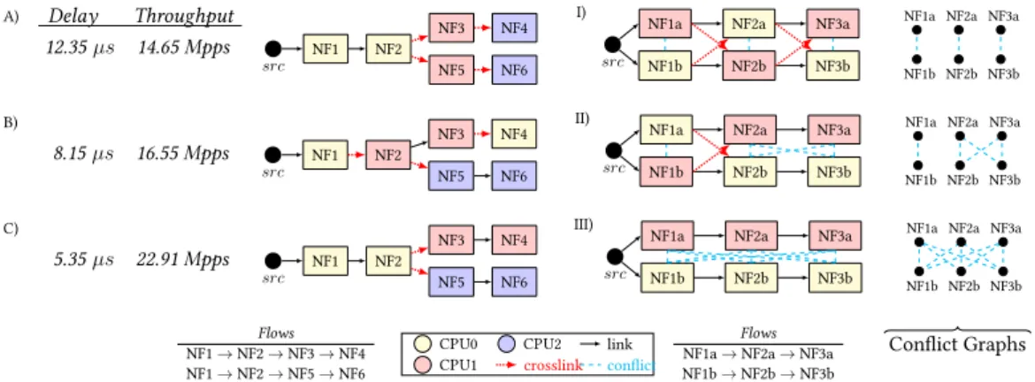
In this chapter, we focus on the embedding of the data flow graph in software switches. In this section, we first introduce motivation and goals for data-flow-graph embedding in software switches. The task of data-flow graph embedding in this context is about assigning each packet processing module in the data-flow graph to a worker (ie, the CPU core) in a way that guarantees 3 crucial goals: feasibility, efficiency, and robustness.
Since even a single CP U failure can lead to a service interruption by breaking the connectivity of the data flow graph, aresilient data flow graph embedding method will ensure that the critical packet. In the above versions of the data flow graph embedding problem, the main concern is to minimize the total number of intersections.
Problem Formulation
This approach is easy to extend to CP U failures by duplicating modules N-times and establishing a conflict between each pair of replicas. Duplicating the complete data flow graph over additional CP Us can achieve full resiliency to CP U failures. However, duplicating the data flow (sub)graphs involves the replication of incoming packets and the removal of outgoing packets, but the replication involves huge overhead, moreover, packet de-duplication is also a challenging technical problem [92, 93].
We note that packed/duplication is beyond the scope of this work, see [92, 93].). Even if a CP U stops, the packets of the high-availability flow (flow1) continue to be processed without interruption thanks to the careful nesting.
New Results
- Complexity Analysis
- Exact Algorithm
- Heuristic Approach
- Numerical Evaluation
- Case Study
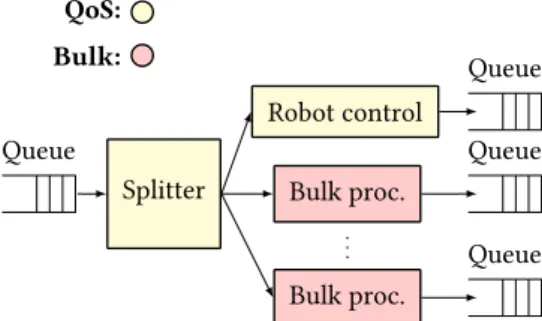
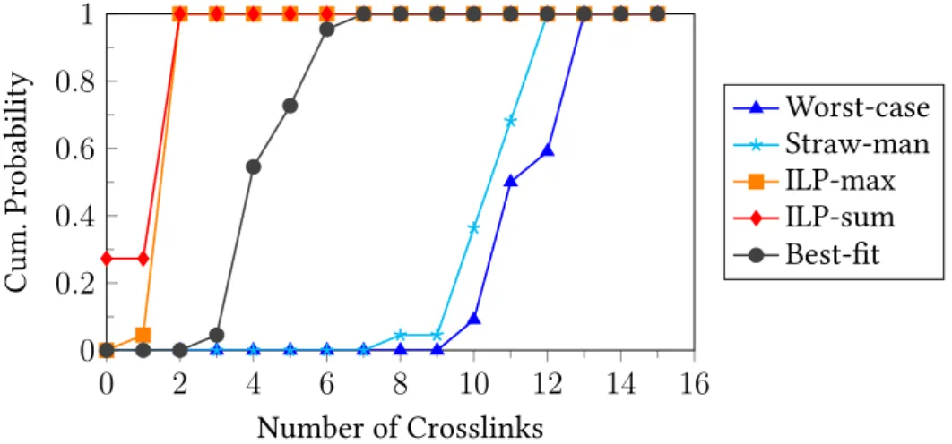
Finally, since the bin-packing instance does not account for minimizing the number of intersections (i.e., the number of intersections is set to ∞ in the minimization), the embedding problem is NP-hard for both the total (MinSumEmbed) and the maximum (MinMaxEmbed) objective functions. Worst-case embedding. The result produced by this algorithm will be used in our evaluations as a "heuristic worst-case", whereby we attempt to maximize the number of intersections in the embedding. In our evaluations, bearer0 (both uplink and downlink) represents high-availability mobile voice and multimedia traffic with firm resiliency requirements (QoS nodes in Figure 3.2); the rest of the carriers represent bulk traffic with no resiliency requirement.
Embedding a data flow graph with minimal transitions. In our first evaluations, we examine the performance of heuristics and ILPs without robustness constraints. Extensibility. Runtime is an important metric in this context, as the data flow graph may need to be remapped to the underlying hardware each time the processing logic changes (eg, each time a new user is enabled in the mobile gateway).
Related Work
Existing work focuses on embedding data flow graphs in the context of software switching and VNF chaining. If there is room for parallelism, a load balancer and join is inserted and the parallel paths are built from subgraphs of the dataflow graph. Alpine achieves this by carefully distributing the data flow graph across tasks and deriving scheduling policies that enforce SLO requirements while maximizing performance.
To our knowledge, there is no previous work that considers resiliency constraints in powerful embedding of data streams and graphs. Again, we can see that no previous work has been done on resiliency constraints on powerful embedding of data flow graphs in software switches.
Summary
In this dissertation, we are improving and extending the characteristics and performance features of the software switch by optimizing data flow group scheduling and data flow graph embedding (i.e., resource allocation). Using our model, we formulate the optimal scheduling of data flow groups with delay requirements for both scheduling modes (RTC and WFQ). Meanwhile, in Chapter 3 we relax the assumptions of our model and present a controller framework to achieve optimal dataflow cluster scheduling with delay SLOs on a real-life software switcher under real workloads.
Again, embedding data flow graphs is an important factor in software switch performance; remember, bad embedding results in unfeasible data-flow-graph batch-scheduling controller state. Reliable data flow graph embedding ensures that the critical flows are immune to CP U failures.
Application of Results
An efficient embedding minimizes the mapping of data flow graph arcs over CP Us, because inter-CP U-core connections incur a large performance fee. Inclusion objectives expressed as decision problems are NP-hard, so they do not scale well to real-life use cases. Our extensive numerical evaluation and real-life case study show that the best-fit heuristic provides the best approximation of optimal embedding in real-life use cases. in factory automation) require ultra-low latency and high availability for successful operation [4].
Our resilient data-flow-graph embedding ensures high availability, while data-flow-graph batch scheduling optimization delivers low latency. Outside of the telecom world, applications that use data flow graph representation, such as multimedia streaming [39], parallelization [110], big data machine learning [38] and more, can benefit from our results due to the generality of data flow graph representation.
Future Work
This enables strict latency SLOs to be enforced and ensures low latency from the start of a packet processing pipeline. Combining the dataflow graph embedding solution and the optimal dataflow graph batch scheduling controller with latency SLOs together can possibly enable real-time (soft) scheduling.
Theses Summary
The first control algorithm of the controller is a projected gradient control algorithm, presented in Section 3.3.3. Clicknp: Highly flexible and high performance network processing with reconfigurable hardware,” in Proceedings of the 2016 ACM SIGCOMM Conference, ser. Pfaff, "Revisiting the open vswitch data plane ten years later," in Proceedings of the 2021 ACM SIGCOMM 2021 Conference, ser.
Hardening: Achieving Effective Fault Tolerance for Network Function Virtualization-Based Services,” in Proceedings of the 14th International Conference on Emerging Network Experiments and Technologies, 2018, p. Raghavan, “Semi-automated protocol disambiguation and code generation,” in Proceedings of the 2021 ACM SIGCOMM 2021 Conference, ser.
![Figure 2.3: Maximum packet rate (in millions of packets per second) over network function micro-benchmarks in BESS [22] (marked with B) and in FastClick [9] (FC) when varying the input batch size.](https://thumb-eu.123doks.com/thumbv2/9dokorg/2497522.294290/21.892.128.750.283.645/figure-maximum-millions-packets-network-function-benchmarks-fastclick.webp)