However, CAREL and its subsidiaries/affiliates do not warrant that all features of the product and included software will meet the requirements of the final application, even if manufactured using state of the art technology. The lack of this design phase, as indicated in the user manual, may result in a malfunction of the end product for which CAREL cannot be held responsible. The end customer must use the product within the limits of the modes described in the product documentation.
All recommendations mentioned above are also valid for controllers, serial cards, programming keys or other accessories in the CAREL product range. CAREL therefore reserves the right to make changes and/or improvements to any of the products described in this document without prior notice. NOTE: To pay special attention to important topics, especially for the practical use of the various product functions.
INTRODUCTION
Main Characteristics
Parts and Accessories
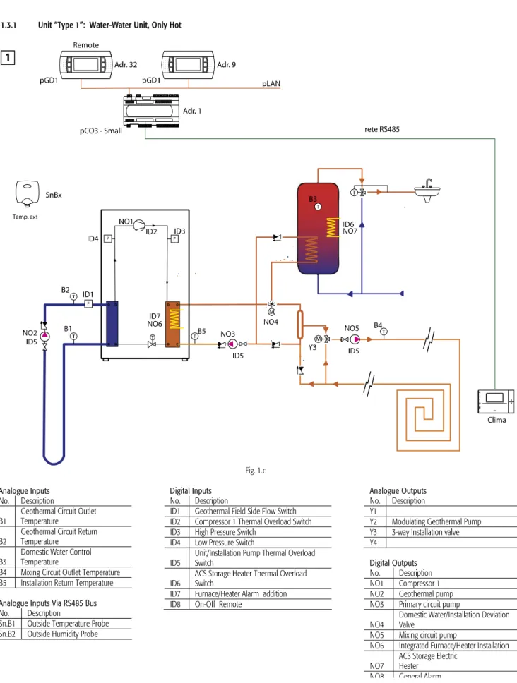
I/O Configurations - Unit Type (Default)
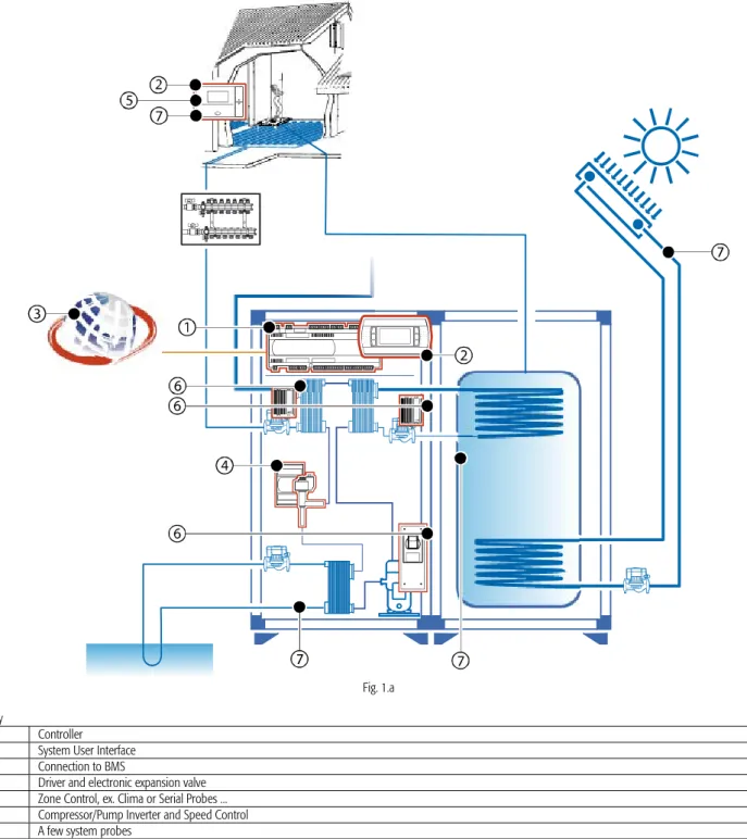
ID1 Geothermal Field Side Flow Switch ID2 Compressor 1 Thermal Overload Switch ID3 High Pressure Switch. Description NO1 Compressor 1 NO2 Geothermal pump NO3 Primary circuit pump NO4 Modulating service water pump NO5 Mixing circuit pump. NO3 Primary circuit pump NO4 Domestic water Circulation pump NO5 Mixing circuit Discharge pump NO6 Installation Integrated oven/heater NO7 ACS Storage Electric heater.
ID1 Geothermal Field Side Flow Switch ID2 Compressor 1 Thermal Overload Switch ID3 High Pressure Switch Comp. NO3 Primary Circulation Pump NO4 Domestic Water Circulation Pump NO5 Mixing Circuit Pump NO6 Installation Integrated Furnace/Heater NO7 ACS Storage Heater. ID1 Geothermal Field Side Flow Switch ID2 Compressor 1 Thermal Overload Switch ID3 High Pressure Switch Comp.
HARDWARE CHARACTERISTICS AND INSTALLATION
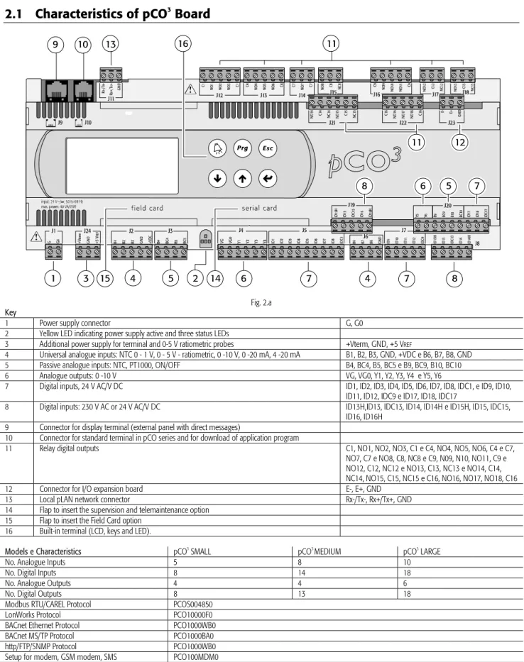
Characteristics of pCO 3 Board
Installation
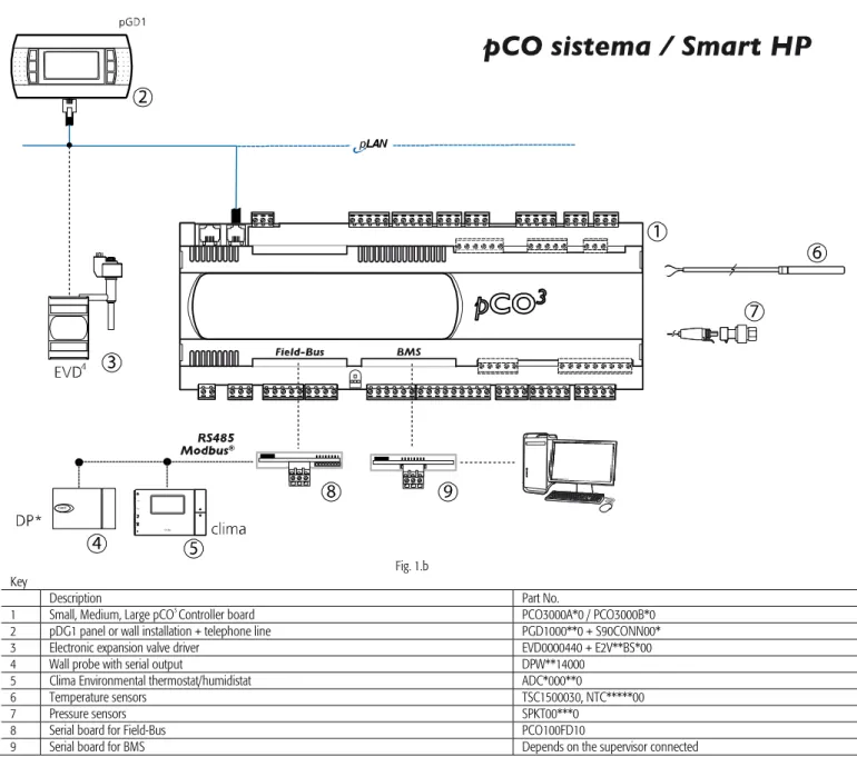
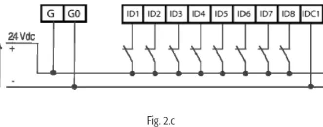
All active temperature and humidity probes in the DP*2 CAREL series configured as 0 - 1 V or 4 - 20 mA can be connected to the pCO board. The following figure shows one of the most common wiring diagrams for connecting the 24 VAC digital inputs. In any case, the inputs are only functionally isolated from the rest of the control.
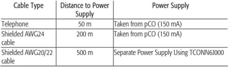
In any case, the inputs have double isolation compared to the rest of the control. The cross-section of the cables for the remote connection of the digital inputs can be found in the following table. The cable cross-section for the remote connection of the digital outputs can be found in the following table.
START UP
Note: For more information on installing and updating software on the pCO controller board, refer to the online help of the pCO Manager program.
SmartKey
First Start Up
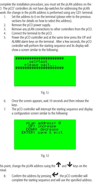
Warning: if during operation the terminal detects an inactive status of the pCO board displaying the output, it completely clears the screen and shows a message similar to the following. The pCO3 controllers do not have dip switches to address the pLAN network: the change in the pLAN address is performed using any GD1 terminal. Set the address to 0 on the terminal (please refer to the previous sections for details on how to select this address).
Turn on the pCO controller and simultaneously press the UP and ALARM alarm keys on the terminal. Confirm the address by pressing: the pCO controller will complete the start sequence and will use the specified address. Note: if the settings are not configured correctly, the text and images displayed on the screen will be incorrect and in the wrong order.
USER INTERFACE
Graphic terminal
Display
MENU DESCRIPTION
- A. On-Off/Mode
- B. Setpoint
- C. Time bands
- D. Inputs/Outputs
- E. Alarm Log
- F. Change Unit
- G. Service
- H. Manufacturer
After that, it is possible to select all the days of the week, by either copying the previous day, or setting each day independently. Consequently, the number of time slots is also reduced because the large inertia of the system is taken into account. From the main menu (D.), you can display, in sequence, both the type and the physical status of the inputs and outputs, both digital and analog.
Change language/unit of measurement: allows you to select one of the languages loaded in the application (Italian, English). Control Unit: allows you to set the set points for the solar panels (if present), the mixing circuit, the anti-freeze function and the heat pump unit (nominal and energy saving, both in "heating/cooling" mode and for domestic water heating). Config./Threshold: Allows you to set the threshold of working hours for the major moving components or components requiring periodic maintenance in the unit (depending on configuration).
Temperature control: in this section you will find all the parameters related to the temperature control that can be modified during installation or installation assistance, with the exception of those that are the responsibility of the manufacturer, which are located in the H.c. Unit configuration: allows you to select the basic characteristics of the unit/installation and the functionality of the individual devices. After that, a series of screens are displayed that define the salient features of the individual system components (e.g. type and number of compressors, etc.) from the configuration allowed by the hardware.
In this menu you can select the functionality and presence of the individually selectable I/Os. For the digital I/Os you can select the state of the device i.e. NO or NC logic. Manufacturer Parameters: This screen allows you to select the parameters that can be set by the manufacturer.
Default/Password: this allows you to select the CAREL default values (when you select CAREL all settings are cleared and the system returns to the default configuration shown in the following manual).
FUNCTIONS
- Compressor Management
- EVD400 Electronic Valve Management
- Antifreeze Function
- Control of the installation Water and the Geothermal Circuit
- Humidify and Dehumidify Management
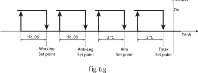
- Domestic Water Temperature Control and Anti-Legionnaire Function
- Solar Panel Management
- Temperature Compensation
- Management of the zones using the Serial probes or Clima
- Recovery Fans
In the primary circuit of the heating function mode, heaters in the heat exchanger or an oven (which receives a remote on/off control and operates with its own set point settings) can be used to integrate the system (digital output NO6 on the pCO3 board. In the cooling mode guarantees the outlet probe of the primary circuit antifreeze protection (please see the section dedicated to the Antifreeze function) for the unit's heat exchanger. The management of the room humidity control is carried out by the primary air handling system and carried out with the help of the readings of the serial probes or Clima present in the rooms.
Humidification and dehumidification control set points operate based on a mathematical average of the readings from the probes/Clima present in the installation and can be set by the end user directly in the Set Point menu (B). End-user settable point limits can be set during installation on the Gfc44 display. For dehumidification, in addition to activating the specific actuator, it is possible to set a safety compensation (selectable in Gfc31) for the outlet temperature of the installation in order to avoid reading the dew point of the rooms.
Continuous or thermostat operation of the domestic water pump is set using the Manufacturer Hc_23 branch. It operates at 35% (fixed) if the water temperature is above the set point, regardless of the choice made on screen Hc_23. For each individual panel, to control the pump functions based on the temperature difference between the panel probe and the lower part of the domestic water tank.
T low Temperature of the lower part of the domestic water tank If there are two panels (one facing east and the other facing west), the set point and the working difference are the same for both. The Gfc23 screen also allows you to set a warning threshold for the domestic water load. When the serial probes are connected, the scheduler/zone duty setpoint uses the average temperature of the activated probes for the respective zone/programmer.
If the device also performs cooling, serial probes or Clima with built-in humidity reading must be used to properly manage the installation (please see the relevant section) and a mixing valve for the temperature (which increases by an adjustable offset, on Gfc31) of the dew point temperature in the individual rooms, to avoid surface condensation.
PARAMETER TABLE
Inverted pump thermal overload switch logic (on unit type 1 or 2), geothermal pump thermal overload switch (on unit type 3, 4, 5 or 6). Invert the circuit breaker logic of the installation circuit (on unit type 4, 5 or 6); Mixing installation pump thermal overload switch (on unit type 3).
VARIABLES SENT TO THE SUPERVISOR
ALARMS
Alarm Management
Alarm Log
Alarm Table
ALB01 * Position: ID3 High pressure compressor 1 Manual Immediately YES Stop compressor(s), geothermal pump, primary circuit and house water circuit. Hc_03; Hc_04) YES Stop compressor(s), geothermal pump, primary circuit and house water circuit. ALB03 * Position: ID10 High pressure compressor 2 manual YES Stop the compressor(s), geothermal pump, primary circuit and house water circuit immediately.
ALD03 Driver MOP Timeout (check timeout) Manual Immediate YES ALD04 Driver Timeout LOP (check timeout) Manual Immediate YES ALD05 Driver Low SuperHeat (check timeout) Manual Immediate YES ALD06 Driver High SuperHeat (check timeout) Manual Immediate YES ALD07 Driver EEV not closed during Driver EEV turns OFF Manual Immediately YES. ALD13 Manager Auto setup Procedure not completed Manual Immediate YES ALP01 * Position: ID1 Water flow switch geothermal side From parameter. Hc_18; Hc_19) YES Stop the compressor(s), the geothermal pump, the primary circuit and the domestic water circuit.
ALP02 * Position: ID5 Goethermal system pump overload. unit manual immediately YES Stop compressor(s), geothermal pump, primary circuit and house water circuit. ALP03 * Position: ID6 Manual Pump System Overload (or Mix . Pump Overload) YES Immediately stop compressor(s), geothermal pump, primary circuit and internal water circuit. ALP04 * Position: ID11 DHW Pump Overload Manual Immediately YES Stop internal water circuit and recovery logic.
ALP05 * Position: ID12 Water flow switch system side Off parameter (Hc_17). Hc_15; Hc_16) YES Stop the compressor(s), geothermal pump, primary circuit, mixing circuit and sanitary water circuit. ALP06 Position: ID15 Pump mixing circuit overloaded Manual YES Stop the mixing circuit pump and close the 3-way valve ALP07 Position: ID17 Pump solar circuit 1 overloaded Manual Immediate. Warning signal ALU01 * Antifreeze ground heat exchanger Off parameter. Gfc36) Immediate YES Stop the compressor(s), geothermal pump, primary circuit and sanitary water circuit.
Gfc38) Immediately YES Stop the compressor(s), the geothermal pump, the primary circuit and the domestic water circuit.