GRUNDFOS DATA BOOKLET
MAGNA1
Circulator pumps
50 Hz
Table of co nte nts
MAGNA1
1. Product description 3
Main applications 3
Type key 4
Performance range, MAGNA1 5 Performance range, MAGNA1 D single-head
operation 6
Performance range, MAGNA1 D twin-head operation 6
2. Product range 7
Single-head pumps 7
Twin-head pumps 8
Pump selection 9
3. Functions 10
System applications 10
Selection of control mode 11
Control modes 12
Control panel 13
Overview of settings 14
4. Operating conditions 15
Pumped liquids 15
Electrical data 16
5. Construction 17
Sectional drawings 18
Material specification 18
6. Installation 19
Mechanical installation 19 Electrical installation 19
Cables 19
Connection diagrams 20
7. Accessories 21
Blanking flanges 21
Counter flanges 22
Adapter for various port-to-port lengths 25 8. Guide to performance curves 29
9. Curve conditions 30
Performance curves 30
10. Performance curves and technical data 31
11. Product numbers 130
MAGNA1 for the international market 130
Single-head pumps 130
Twin-head pumps 131
MAGNA1 for the German market 132
Single-head pumps 132
Twin-head pumps 133
12. Further product documentation 134
WebCAPS 134
WinCAPS 135
GO CAPS 136
Product description
3
MAGNA1 1
1. Product description
The Grundfos MAGNA1 circulator pumps are designed for circulating liquids in the following systems:
• heating systems
• air-conditioning and cooling systems
The pump range can also be used for the following systems:
• ground source heat pump systems
• solar-heating systems.
Duty range
Fig. 1 Single-head MAGNA1 pumps
Characteristic features
• Proportional-pressure control.
• Constant-pressure control.
• Constant-curve/constant-speed duty.
• No external motor protection required.
• Insulating shells supplied with single-head pumps for heating systems.
• Wide temperature range where the liquid temperature and the ambient temperature are independent of each other.
Benefits
• Simple installation.
• Low energy consumption. All MAGNA1 pumps comply with the EuP 2013 and 2015 requirements.
• Eight light fields for indication of pump setting.
• Low noise level.
• No maintenance and long life.
• The complete range is available for a maximum system pressure of 16 bar (PN 16).
Main applications
Heating systems
• Main pump
• mixing loops
• heating surfaces
• air-conditioning surfaces.
The MAGNA1 circulator pumps are designed for circulating liquids in heating systems with variable flows where it is desirable to optimise the setting of the pump duty point, thus reducing energy costs. To ensure correct operation, it is important that the sizing range of the system falls within the duty range of the pump.
Data MAGNA1 (N)
Single-head pumps
MAGNA1 D Twin-head pumps Maximum flow rate, Q 71 m3/h 110 m3/h
Maximum head, H 18 metres
Maximum system pressure 1.6 MPa (16 bar) Liquid temperature -10 °C to +110 °C
TM05 5862 4112 - TM05 5863 4112
Pro duct descriptio n
MAGNA1
1
Type key
Code Example MAGNA1 D 80 -120 (F) 360
Type range MAGNA1
D Twin-head pump
Nominal diameter (DN) of suction and discharge ports [mm]
Maximum head [dm]
F
Pipe connection Threaded Flange
Port-to-port length [mm]
Product description
5
MAGNA1 1
Performance range, MAGNA1
Fig. 2 Performance range, MAGNA1
TM05 6372 4612
2 3 4 5 6 7 8 1 01 5 2 03 0 4 0 5 0 6 0 7 0 Q [m³/h]
2
2
3
4
5
6
8 10
12
15
18 [m] H 112 3 4 5 6 7 8 9 1 0 10 Q [l/s]
15
20
30
40
50
60
70
80
90 100100
[kPa] p MAGNA1
50-180 40-180 65-150 50-15040-150100-120
80-12065-12050-12040-120 100-10080-10065-100 50-10040-100 100-8080-8065-80 50-80
40-80 100-6080-6065-6050-60 100-4080-4065-4050-40
40-60 40-40
32-100 32-80 32-60 32-40
25-120 25-100 25-80 25-60 25-40
32-120
1 1.5
Pro duct descriptio n
MAGNA1
1
Performance range, MAGNA1 D single-head operation
Fig. 3 Performance range, MAGNA1 D single-head operation
Performance range, MAGNA1 D twin-head operation
TM05 6373 461205 6374 4612
2 3 4 5 6 7 8 10 15 20 30 40 50 60 70
Q [m³/h]
2 2 3 4 5 6 8 10 12 15 18 [m]
H
1
1 2 3 4 5 6 7 8 9 1010 Q [l/s]
15 20 30 40 50 60 70 80 90 100 100 [kPa]
p
MAGNA1 D
50-180 40-180
65-150 50-150
40-150
100-120 80-120
65-120 50-120
40-120 32-120
100-100 80-100
65-100 50-100
40-100 32-100
100-80 80-80
65-80 50-80 40-80
32-80
100-60 80-60
65-60 50-60 40-60
32-60
100-40 80-40
65-40 50-40 40-40
32-40
1 1.5
2 3 4 5 6 7 8 10 12 15 20 30 40 50 60 70 80 100 120
Q [m³/h]
2 2 3 4 5 6 8 10 12 15 18 [m]
H
1
1 2 3 4 5 6 7 8 9 1010 20 Q [l/s]
15 20 30 40 50 60 70 80 90 100 100 [kPa]
p
MAGNA1 D
50-180 40-180
65-150
50-150 40-150
100- 80-120 120 65-120
50-12040-120 32-120
100-100 80-100
65-100 50-100 40-100 32-100
100-80 80-80
65-80 50-80 40-80 32-80
100-60 80-60
65-60 50-60 40-60
32-60
100-40 80-40
65-40 50-40
40-40 32-40
1 1.5
Product range
7
MAGNA1 2
2. Product range
Single-head pumps
Note: The product numbers of the various pump variants can be found on page 130.
Pump type Port-to-port length [mm]
Threaded pipe connection
Data sheet Cast iron Page
PN 6/10 PN 16
MAGNA1 25-40 180 ● ● 31
MAGNA1 25-60 180 ● ● 33
MAGNA1 25-80 180 ● ● 35
MAGNA1 25-100 180 ● ● 37
MAGNA1 25-120 180 ● ● 39
MAGNA1 32-40 180 ● ● 40
MAGNA1 32-60 180 ● ● 44
MAGNA1 32-80 180 ● ● 48
MAGNA1 32-100 180 ● ● 52
Pump type Port-to-port length [mm]
Flange connection
Data sheet Cast iron Page
PN 6 PN 10 PN 6/10 PN 16
MAGNA1 32-40 F 220 ● ● 54
MAGNA1 32-60 F 220 ● ● 58
MAGNA1 32-80 F 220 ● ● 62
MAGNA1 32-100 F 220 ● ● 66
MAGNA1 32-120 F 220 ● ● 68
MAGNA1 40-40 F 220 ● ● 70
MAGNA1 40-60 F 220 ● ● 72
MAGNA1 40-80 F 220 ● ● 74
MAGNA1 40-100 F 220 ● ● 76
MAGNA1 40-120 F 250 ● ● 78
MAGNA1 40-150 F 250 ● ● 80
MAGNA1 40-180 F 250 ● ● 82
MAGNA1 50-40 F 240 ● ● 84
MAGNA1 50-60 F 240 ● ● 86
MAGNA1 50-80 F 240 ● ● 88
MAGNA1 50-100 F 280 ● ● 90
MAGNA1 50-120 F 280 ● ● 92
MAGNA1 50-150 F 280 ● ● 94
MAGNA1 50-180 F 280 ● ● 96
MAGNA1 65-40 F 340 ● ● 98
MAGNA1 65-60 F 340 ● ● 100
MAGNA1 65-80 F 340 ● ● 102
MAGNA1 65-100 F 340 ● ● 104
MAGNA1 65-120 F 340 ● ● 106
MAGNA1 65-150 F 340 ● ● 108
MAGNA1 80-40 F 360 ● ● ● 110
MAGNA1 80-60 F 360 ● ● ● 112
MAGNA1 80-80 F 360 ● ● ● 114
MAGNA1 80-100 F 360 ● ● ● 116
MAGNA1 80-120 F 360 ● ● ● 118
MAGNA1 100-40 F 450 ● ● ● 120
MAGNA1 100-60 F 450 ● ● ● 122
MAGNA1 100-80 F 450 ● ● ● 124
MAGNA1 100-100 F 450 ● ● ● 126
MAGNA1 100-120 F 450 ● ● ● 128
Pro duct range
MAGNA1
2
Twin-head pumps
Note: The product numbers of the various pump variants can be found on page 130.
Pump type Port-to-port length [mm]
Threaded pipe connection
Data sheet Cast iron Page
PN 6/10 PN 16
MAGNA1 D 32-40 180 ● ● 42
MAGNA1 D 32-60 180 ● ● 46
MAGNA1 D 32-80 180 ● ● 50
MAGNA1 D 32-100 180 ● ● 53
Pump type Port-to-port length [mm]
Flange connection
Data sheet Cast iron Page
PN 6 PN 10 PN 6/10 PN 16
MAGNA1 D 32-40 F 220 ● ● 56
MAGNA1 D 32-60 F 220 ● ● 60
MAGNA1 D 32-80 F 220 ● ● 64
MAGNA1 D 32-100 F 220 ● ● 67
MAGNA1 D 32-120 F 220 ● ● 69
MAGNA1 D 40-40 F 220 ● ● 71
MAGNA1 D 40-60 F 220 ● ● 73
MAGNA1 D 40-80 F 220 ● ● 75
MAGNA1 D 40-100 F 220 ● ● 77
MAGNA1 D 40-120 F 250 ● ● 79
MAGNA1 D 40-150 F 250 ● ● 81
MAGNA1 D 40-180 F 250 ● ● 83
MAGNA1 D 50-40 F 240 ● ● 85
MAGNA1 D 50-60 F 240 ● ● 87
MAGNA1 D 50-80 F 240 ● ● 89
MAGNA1 D 50-100 F 280 ● ● 91
MAGNA1 D 50-120 F 280 ● ● 93
MAGNA1 D 50-150 F 280 ● ● 95
MAGNA1 D 50-180 F 280 ● ● 97
MAGNA1 D 65-40 F 340 ● ● 99
MAGNA1 D 65-60 F 340 ● ● 101
MAGNA1 D 65-80 F 340 ● ● 103
MAGNA1 D 65-100 F 340 ● ● 105
MAGNA1 D 65-120 F 340 ● ● 107
MAGNA1 D 65-150 F 340 ● ● 109
MAGNA1 D 80-40 F 360 ● ● ● 111
MAGNA1 D 80-60 F 360 ● ● ● 113
MAGNA1 D 80-80 F 360 ● ● ● 115
MAGNA1 D 80-100 F 360 ● ● ● 117
MAGNA1 D 80-120 F 360 ● ● ● 119
MAGNA1 D 100-40 F 450 ● ● ● 121
MAGNA1 D 100-60 F 450 ● ● ● 123
MAGNA1 D 100-80 F 450 ● ● ● 125
MAGNA1 D 100-100 F 450 ● ● ● 127
MAGNA1 D 100-120 F 450 ● ● ● 129
Product range
9
MAGNA1 2
Pump selection
Pump size
The selection of pump size should be based on the following:
• required maximum flow
• maximum pressure loss in the system.
Refer to the system characteristics to determine the duty point. See fig. 5.
Fig. 5 System characteristic
Operating conditions
It should be checked whether the operating conditions are fulfilled, i.e.
• liquid quality and temperature
• ambient conditions
• minimum inlet pressure
• maximum operating pressure.
Control modes
• Proportional-pressure control in systems with considerable pressure losses in relation to large flow variations.
• Constant-pressure control in systems with
insignificant pressure losses in relation to large flow variations.
• In constant-curve/constant-speed operation, the pump will run at a constant speed, independent of the actual flow demand in the system.
TM02 2040 3301
Q Duty point H
Functions
MAGNA1
3
3. Functions
System applications
Heating systems
TM01 0168 0697
• One- and two-pipe heating systems
• Main pumps
• Zone pumps
• Mixing loops
• Boiler shunt pumps
• Pumps for heating surfaces
• Calorifiers
• Underfloor-heating systems
• Solar-heating systems
• Ground source heat pump systems
• Heat recovery systems.
Air-conditioning and cooling systems
TM01 0170 0697
• Two-pipe air-conditioning systems
• Main pumps
• Zone pumps
• Pumps for refrigeration units
• Heat pump systems
• Ground source heat pump systems
• Heat recovery systems
• Air-conditioning surfaces.
M M
M
M M
Out In
M
M M
Fun ctions
11
MAGNA1 3
Selection of control mode
System application Select this control
mode In systems with relatively large pressure losses in the distribution pipes and in air-conditioning
and cooling systems.
• Two-pipe heating systems with thermostatic valves and – very long distribution pipes
– strongly throttled pipe balancing valves – differential-pressure regulators
– large pressure losses in those parts of the system through which the total quantity of water flows (for example boiler, heat exchanger and distribution pipe up to the first branching).
• Primary circuit pumps in systems with large pressure losses in the primary circuit.
• Air-conditioning systems with – heat exchangers (fan coils) – cooling ceilings
– cooling surfaces.
Proportional pressure
In systems with relatively small pressure losses in the distribution pipes.
• Two-pipe heating systems with thermostatic valves and – dimensioned for natural circulation
– small pressure losses in those parts of the system through which the total quantity of water flows (for example boiler, heat exchanger and distribution pipe up to the first branching) or
– modified to a high differential temperature between flow pipe and return pipe (for example district heating).
• Underfloor heating systems with thermostatic valves.
• One-pipe heating systems with thermostatic valves or pipe balancing valves.
• Primary circuit pumps in systems with small pressure losses in the primary circuit.
Constant pressure
The pump can also be set to operate according to the max. or min. curve, like an uncontrolled pump:
• The max. curve mode can be used in periods in which a maximum flow is required.
This operating mode is for instance suitable for hot-water priority.
• The min. curve mode can be used in periods in which a minimum flow is required.
This operating mode is for instance suitable for manual night setback.
Constant curve
Q H
Q H
Q H
Functions
MAGNA1
3
Control modes
Fig. 6 Selection of pump setting for system type
Factory setting: Intermediate proportional-pressure curve, referred to as PP2.
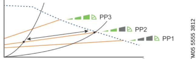
Proportional-pressure curve (PP1, PP2 or PP3)
Proportional-pressure control adjusts the pump performance to the actual heat demand in the system, but the pump performance follows the selected performance curve, PP1, PP2 or PP3. See fig. 7 where PP2 has been selected.
See Selection of control mode , page 11, for further information.
Fig. 7 Three proportional-pressure curves/settings
The selection of the right proportional-pressure setting depends on the characteristics of the heating system in question and the actual heat demand.
Constant-pressure curve (CP1, CP2 or CP3)
Constant-pressure control adjusts the pump
performance to the actual heat demand in the system, but the pump performance follows the selected performance curve, CP1, CP2 or CP3. See fig. 8 where CP1 has been selected.
See Selection of control mode , page 11, for further information.
Fig. 8 Three constant-pressure curves/settings
The selection of the right constant-pressure setting depends on the characteristics of the heating system
Constant curve/constant speed (I, II or III)
In constant-curve/constant-speed operation, the pump will run at a constant speed, independent of the actual flow demand in the system. The pump performance follows the selected performance curve, I, II or III.
See fig. 9 where II has been selected.
See Selection of control mode , page 11, for further information.
Fig. 9 Three constant curve/constant speed settings
The selection of the right
constant-curve/constant-speed setting depends on the characteristics of the heating system in question.
TM05 5554 3812TM05 5555 3812TM05 5556 3812
Q H
PP3
PP2 PP1
Q H
Q H
CP3
CP2
CP1
TM05 5557 3812
Q H
Fun ctions
13
MAGNA1 3
Control panel
Fig. 10 Control panel at first start-up
The control panel on the pump comprises the following:
Grundfos Eye
The Grundfos Eye is on when the power supply has been switched on. See fig. 10, pos. 1.
The Grundfos Eye is an indicator light providing information about the actual pump status.
The indicator light will flash in different sequences and provide information about the following:
• power on/off
• pump alarms.
Light fields indicating the pump setting
The pump has nine optional performance settings which can be selected with the push-button.
See fig. 10, pos. 3.
The pump setting is indicated by eight light fields in the display. See fig. 10, pos. 2.
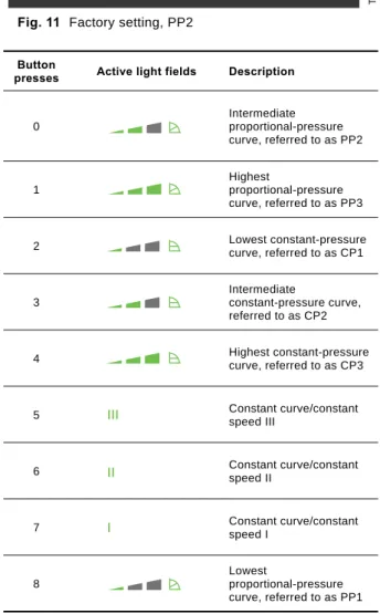
Fig. 11 Factory setting, PP2
TM05 5552 3812
Pos. Description
1 Grundfos Eye operating status.
See section Grundfos Eye.
2 Eight light fields indicating the pump setting.
See section Light fields indicating the pump setting.
3 Push-button for selection of pump setting.
1 2
3 TM
05 5553 3812
Button
presses Active light fields Description
0
Intermediate proportional-pressure curve, referred to as PP2
1
Highest
proportional-pressure curve, referred to as PP3
2 Lowest constant-pressure
curve, referred to as CP1
3
Intermediate
constant-pressure curve, referred to as CP2
4 Highest constant-pressure
curve, referred to as CP3
5 Constant curve/constant
speed III
6 Constant curve/constant
speed II
7 Constant curve/constant
speed I
8
Lowest
proportional-pressure curve, referred to as PP1
Functions
MAGNA1
3
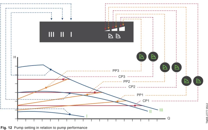
Overview of settings
Fig. 12 Pump setting in relation to pump performance
TM05 2777 0512
II III I
H
PP3 CP3
CP2 PP1
CP1 PP2
Q
Setting Pump curve Function
PP1
Lowest
proportional-pressure curve
The duty point of the pump will move up or down on the lowest proportional-pressure curve, depending on the heat demand. See fig. 12.
The head (pressure) is reduced at falling heat demand and increased at rising heat demand.
PP2
Intermediate proportional-pressure curve
The duty point of the pump will move up or down on the intermediate proportional-pressure curve, depending on the heat demand. See fig. 12.
The head (pressure) is reduced at falling heat demand and increased at rising heat demand.
PP3
Highest
proportional-pressure curve
The duty point of the pump will move up or down on the highest proportional-pressure curve, depending on the heat demand. See fig. 12.
The head (pressure) is reduced at falling heat demand and increased at rising heat demand.
CP1 Lowest
constant-pressure curve
The duty point of the pump will move out or in on the lowest constant-pressure curve, depending on the heat demand in the system. See fig. 12.
The head (pressure) is kept constant, irrespective of the heat demand.
CP2 Intermediate
constant-pressure curve
The duty point of the pump will move out or in on the intermediate constant-pressure curve, depending on the heat demand in the system. See fig. 12.
The head (pressure) is kept constant, irrespective of the heat demand.
CP3 Highest
constant-pressure curve
The duty point of the pump will move out or in on the highest constant-pressure curve, depending on the heat demand in the system. See fig. 12.
The head (pressure) is kept constant, irrespective of the heat demand.
III Speed III
The pump runs on a constant curve which means that it runs at a constant speed.
In speed III, the pump is set to run on the max. curve under all operating conditions. See fig. 12.
Quick venting of the pump can be obtained by setting the pump to speed III for a short period.
II Speed II
The pump runs on a constant curve which means that it runs at a constant speed.
In speed II, the pump is set to run on the intermediate curve under all operating conditions.
See fig. 12.
I Speed I The pump runs on a constant curve which means that it runs at a constant speed.
In speed I, the pump is set to run on the min. curve under all operating conditions. See fig. 12.
Operating conditions
15
MAGNA1 4
4. Operating conditions
General recommendations
Liquid temperature
-10 to +110 °C.
Ambient conditions
Maximum operating pressure
PN 6: 6 bar / 0.6 MPa PN 10: 10 bar / 1.0 MPa PN 16: 16 bar / 1.6 MPa.
Minimum inlet pressure
The following relative minimum inlet pressure must be available at the pump inlet during operation to avoid cavitation noise and damage to the pump bearings.
Note: The values in the table below apply to single-head pumps and twin-head pumps in single-head operation.
In the case of twin-head operation, the required relative inlet pressure must be increased by 0.1 bar / 0.01 MPa compared to the stated values for
single-head pumps or twin-head pumps in single-head operation.
Note: The actual inlet pressure plus pump pressure against a closed valve must be lower than the maximum permissible system pressure.
The relative minimum inlet pressures apply to pumps installed up to 300 metres above sea level. For altitudes above 300 metres, the required relative inlet pressure must be increased by 0.01 bar / 0.001 MPa per 100 metres altitude. The MAGNA1 pump is only approved for an altitude of 2000 metres above sea level.
Pumped liquids
The pump is suitable for thin, clean, non-aggressive and non-explosive liquids, not containing solid particles or fibres that may attack the pump mechanically or chemically.
In heating systems, the water should meet the requirements of accepted standards on water quality in heating systems, for example the German standard VDI 2035.
Do not use the pump for flammable liquids, such as diesel oil and petrol.
Do not use the pump for aggressive liquids, such as acids and seawater.
If the pump is not used during periods of frost, necessary steps must be taken to prevent frost bursts.
Additives with a density and/or kinematic viscosity higher than those/that of water will reduce the hydraulic performance.
Do not use additives that in any way can/will disturb the functionality of the pump.
Whether a pump is suitable for a particular liquid depends on a number of factors of which the most important are lime content, pH value, temperature, content of solvents and oils.
The pump can be used for pumping water/glycol mixtures up to 50 %. See section General recommendations .
The pumping of glycol mixtures will reduce the hydraulic performance.
Water in heating
systems Water quality according to local standards such as the German standard VDI 2035 Water containing glycol Maximum viscosity = 15 mm2/s
(~ 50 % glycol at +2 °C)
Ambient temperature during
operation 0 to +40 °C
Ambient temperature during
storage and transport -30 to +55 °C
Relative air humidity Max. 95 %
Single-head pumps DN
Liquid temperature
75 °C 95 °C 110 °C
Inlet pressure [bar] / [MPa]
25-40/60/80/100/120 0.10 / 0.01 0.35 / 0.035 1.0 / 0.10 32-40/60/80/100 0.10 / 0.01 0.35 / 0.035 1.0 / 0.10 32-120 0.90 / 0.09 1.30 / 0.13 1.9 / 0.19 40-40/60 0.10 / 0.01 0.35 / 0.035 1.0 / 0.10 40-80/100 0.10 / 0.01 0.50 / 0.05 1.0 / 0.10 40-120/150/180 0.10 / 0.01 0.50 / 0.05 1.0 / 0.10 50-40/60/80 0.10 / 0.01 0.40 / 0.04 1.0 / 0.10 50-100 0.10 / 0.01 0.50 / 0.05 1.0 / 0.10 50-120 0.10 / 0.01 0.50 / 0.05 1.0 / 0.10 50-150/180 0.70 / 0.07 1.20 / 0.12 1.7 / 0.17 65-40/60/80/100 0.70 / 0.07 1.20 / 0.12 1.7 / 0.17 65-120 0.70 / 0.07 1.20 / 0.12 1.7 / 0.17 65-150 0.70 / 0.07 1.20 / 0.12 1.7 / 0.17 80-40/60/80/100/120 0.50 / 0.05 1.00 / 0.10 1.5 / 0.15 100-40/60/80/100/120 0.70 / 0.07 1.20 / 0.12 1.7 / 0.17
Operatin g cond itions
MAGNA1
4
Electrical data
Sound pressure level
Pump type MAGNA1 (D)
Enclosure class IPX4D (EN 60529).
Insulation class F.
Supply voltage 1 x 230 V ± 10 % 50/60 Hz, PE.
Leakage current Ileakage < 3.5 mA.
The leakage current is measured in accordance with EN 60335-1.
EMC EN 55014-1:2006, EN 55014-2:1998, EN 61800-3-3:2008 and EN 61000-3-2:2006.
Pump type MAGNA1 (D)
Sound pressure level ≤43 dB(A)
Construction
17
MAGNA1 5
5. Construction
The MAGNA1 is of the canned-rotor type, i.e. pump and motor form an integral unit without shaft seal and with only two gaskets for sealing. The bearings are lubricated by the pumped liquid.
The pump is characterised by the following:
• controller integrated in the control box
• control panel on the control box
• twin-head versions
• no external motor protection required
• insulating shells supplied with single-head pumps for heating systems.
Motor and electronic controller
The MAGNA1 incorporates a 4-pole synchronous, permanent-magnet motor (PM motor). This motor type is characterised by higher efficiency than a
conventional asynchronous squirrel-cage motor.
The pump speed is controlled by an integrated frequency converter.
Pump connections
Threaded pipe connections according to ISO 228-1.
Flange dimensions according to EN 1092-2.
Surface treatment
The pump housing and pump head are electrocoated to improve the corrosion resistance.
Electrocoating includes:
• alkaline cleaning
• pretreatment with zinc phosphate coating
• cathodic electrocoating (epoxy)
• curing of paint film at 200 to 250 °C.
Co nst ruct ion
MAGNA1
5
Sectional drawings
Fig. 13 Flanged version with PPS-composite rotor can Fig. 14 Threaded version with stainless-steel rotor can
Material specification
See figs 13 and 14.
Rotor can materials
MAGNA1 25-40/60/80/100 (PN 6/10) and MAGNA1 32-40/60/80 (PN 6/10) have stainless-steel rotor can.
All other versions have PPS-composite rotor can. See below table.
TM05 2319 3012 TM05 4962 4112
Pos. Component Material EN
1 Outer bearing ring Aluminium oxide
2 Control box Polycarbonate
3 Stator housing Aluminium
O-rings/gaskets EPDM
4 Thrust bearing Aluminium oxide/carbon
5 Bearing plate Stainless steel EN 1.4301
6 Neck ring Stainless steel EN 1.4301
7 Impeller PES
8 Pump housing Cast iron EN 1561 EN-GJL-250
9 Rotor can PPS or stainless steel
10 Shaft Stainless steel EN 1.4404
Pump type Maximum system pressure
PN 6 / 0.6 MPa PN 10 / 1.0 MPa PN 16 / 1.6 MPa
MAGNA1 25-40/60/80/100 Stainless-steel rotor can
PPS-composite rotor can
MAGNA1 25-120 PPS-composite rotor can
MAGNA1 32-40/60/80 Stainless-steel rotor can
MAGNA1 32-100/120
PPS-composite rotor can MAGNA1 40-40/60/80/100/120/150/180
MAGNA1 50-40/60/80/100/120/150/180 MAGNA1 65-40/60/80/100/120/150 MAGNA1 80-40/60/80/100/120 MAGNA1 100-40/60/80/100/120
Inst allation
19
MAGNA1 6
6. Installation
Mechanical installation
The MAGNA1 is designed for indoor installation.
The pump must be installed with horizontal motor shaft.
The pump may be installed in horizontal as well as vertical pipes.
Fig. 15 Installation positions
Arrows on the pump housing indicate the liquid flow direction through the pump.
The control box must be in horizontal position with the Grundfos logo in vertical position. See fig. 15.
This is described in the installation and operating instructions.
The pump must be installed in such a way that it is not stressed by the pipework.
The pump may be suspended direct in the pipes, provided that the pipework can support the pump.
Twin-head pumps are prepared for installation on a mounting bracket or base plate.
To ensure adequate cooling of motor and electronics, the following must be observed:
• Position the pump in such a way that sufficient cooling is ensured.
• The ambient temperature must not exceed +40 °C.
Insulating shells
The insulating shells supplied with single-head MAGNA1 pumps are for heating systems and should be fitted as part of the installation.
Insulating shells for pumps for air-conditioning and cooling systems are available as an accessory.
See section Insulating kits for air-conditioning and cooling systems , page 21.
Note: Insulating shells are not available for twin-head pumps.
Electrical installation
The electrical connection and protection should be carried out in accordance with local regulations.
• The pump must be connected to an external mains switch.
• The pump must always be correctly earthed.
• The pump requires no external motor protection.
• The pump incorporates thermal protection against slow overloading and blocking.
• When switched on via the power supply, the pump will start pumping after approx. 5 seconds.
Note: The number of starts and stops via the power supply must not exceed four times per hour.
The pump mains connection must be made as shown in fig. 16 or 17, page 20.
Cables
• All cables used must be connected in accordance with local regulations.
Additional protection
If the pump is connected to an electric installation where an earth leakage circuit breaker (ELCB) is used as an additional protection, this circuit breaker must trip when earth fault currents with DC content (pulsating DC) occur.
The earth leakage circuit breaker must be marked with the first or both of the symbols shown below:
TM05 5518 3812
Symbol Description
High-sensitivity ELCB, type A, according to IEC 60775
High-sensitivity ELCB, type B, according to IEC 60775
Inst allation
MAGNA1
6
Connection diagrams
Fig. 16 Example of terminal connection, 1 x 230 V ± 10 %, 50/60 Hz, PE
Fig. 17 Example of ALPHA plug connection, 1 x 230 V ± 10 %, 50/60 Hz, PE
TM03 2397 3712TM05 5277 3712
External switch
Fuse (min. 10 A, time lag) ELCB
External switch Fuse
(min. 10 A, time lag) ELCB
Acc essories
21
MAGNA1 7
7. Accessories
Insulating kits for air-conditioning and cooling systems
Single-head pumps for air-conditioning and cooling systems can be fitted with insulating shells. A kit consists of two shells made of polyurethane (PUR) and a self-adhesive seal to ensure tight assembly.
Fig. 18 Fitting the insulating shells to a MAGNA1 pump
Blanking flanges
A blanking flange is used to blank off the opening when one of the pumps of a twin-head pump is removed for service to enable uninterrupted operation of the other pump.
Fig. 19 Position of blanking flange
TM05 5529 3812
Pump type Product number
MAGNA1 25-40/60/80/100/120 98354534
MAGNA1 32-40/60/80/100/120 98354535
MAGNA1 32-40/60/80/100 F 98354536
MAGNA1 32-120 F 98063287
MAGNA1 40-40/60 98354537
MAGNA1 40-80/100 F 98063288
MAGNA1 40-120/150/180 F 98145675
MAGNA1 50-40/60/80 F 98063289
MAGNA1 50-100/120/150/180 F 98145676 MAGNA1 65-40/60/80/100/120/150 F 96913593 MAGNA1 80-40/60/80/100/120 F 98134265 MAGNA1 100-40/60/80/100/120 F 96913589
TM05 5525 3812
Pump type Product number
MAGNA1 25-40/60/80/100/120 MAGNA1 32-40/60/80/100 (F) MAGNA1 40-40/60 F
98159373 MAGNA1 32-120 F
MAGNA1 40-/80/100/120/150/180 F MAGNA1 50-40/60/80/100/120/150/180 F MAGNA1 65-40/60/80/100/120/150 F MAGNA1 80-40/60/80/100/120 F MAGNA1 100-40/60/80/100/120 F
98159372
Accessories
MAGNA1
7
Counter flanges
Cast-iron pumps
A counter-flange kit consists of two stainless-steel flanges, two gaskets of asbestos-free material IT 200 and the required number of bolts and nuts.
Counter flange Pump type Description Rated pressure
(EN 1092-2) Pipework
connection Product number
TM03 0478 5204
MAGNA1 DN 32
Threaded 10 bar Rp 1 1/4 539703
For welding 10 bar 32 mm,
nominal 539704
Threaded 16 bar Rp 1 1/4 539703
For welding 16 bar 32 mm,
nominal 539704
TM03 0479 5204
MAGNA1 DN 40
Threaded 10 bar Rp 1 1/2 539701
For welding 10 bar 40 mm,
nominal 539702
Threaded 16 bar Rp 1 1/2 539701
For welding 16 bar 40 mm,
nominal 539702
TM03 0480 5204
MAGNA1 DN 50
Threaded 10 bar Rp 2 549801
For welding 10 bar 50 mm,
nominal 549802
Threaded 16 bar Rp 2 549801
For welding 16 bar 50 mm,
nominal 549802
TM03 0481 5204
MAGNA1 DN 65
Threaded 10 bar Rp 2 1/2 559801
For welding 10 bar 65 mm,
nominal 559802
Threaded 16 bar Rp 2 1/2 559801
For welding 16 bar 65 mm,
nominal 559802
5204
MAGNA1 DN 80
Threaded 6 bar Rp 3 569902
For welding 6 bar 80 mm,
nominal 569901
Threaded 10 bar Rp 3 569802
For welding 10 bar 80 mm,
nominal 569801
Threaded 16 bar Rp 3 569802
ø19
ø140 ø100ø78 Rp 1¼
Threaded For welding
ø19
ø150ø110ø88 Rp 1½
Threaded For welding
ø19
ø165ø125 ø102 Rp 2
Threaded For welding
ø19
ø185ø145 ø122 Rp 2½
Threaded For welding
ø19
ø200 ø160 ø138 Rp 3
Threaded For welding
Acc essories
23
MAGNA1 7
TM03 0483 5204
MAGNA1 DN 100
Threaded 6 bar Rp 4 579901
For welding 6 bar 100 mm,
nominal 579902
Threaded 10 bar Rp 4 579801
For welding 10 bar 100 mm,
nominal 579802
Threaded 16 bar Rp 4 579801
For welding 16 bar 100 mm,
nominal 579802 Counter flange Pump type Description Rated pressure
(EN 1092-2) Pipework
connection Product number
ø19
ø220 ø180 ø158 Rp 4
Threaded For welding
Accessories
MAGNA1
7
Stainless-steel pumps
A counter-flange kit consists of two bronze flanges, two gaskets of asbestos-free material IT 200 and the required number of bolts and nuts.
Counter flange Pump type Description Rated pressure
(EN 1092-2) Pipework
connection Product number
TM03 0478 5204
MAGNA1 DN 32
Threaded 10 bar Rp 1 1/4 96427029
For welding 10 bar 32 mm,
nominal 96427030
Threaded 16 bar Rp 1 1/4 96427029
For welding 16 bar 32 mm,
nominal 96427030
TM03 0479 5204
MAGNA1 DN 40
Threaded 10 bar Rp 1 1/2 539711
For welding 10 bar 40 mm,
nominal 539712
Threaded 16 bar Rp 1 1/2 539711
For welding 16 bar 40 mm,
nominal 539712
TM03 0480 5204 MAGNA1 DN 50
Threaded 10 bar Rp 2 549811
For welding 10 bar 50 mm,
nominal 549812
TM03 0481 5204 MAGNA1 DN 65
Threaded 10 bar Rp 2 1/2 559811
For welding 10 bar 65 mm,
nominal 559812
TM03 0482 5204
MAGNA1 DN 80
Threaded 6 bar Rp 3 96405735
For welding 6 bar 80 mm,
nominal 569911
Threaded 10 bar Rp 3 569812
For welding 10 bar 80 mm,
nominal 569811
TM03 0485 5204 MAGNA1 DN 100
Threaded 6 bar Rp 4 96405737
Threaded 10 bar Rp 4 96405738
ø19
ø140 ø100ø78 Rp 1¼
Threaded For welding
ø19
ø150ø110ø88 Rp 1½
Threaded For welding
ø19
ø165ø125 ø102 Rp 2
Threaded For welding
ø19
ø185ø145 ø122 Rp 2½
Threaded For welding
ø19
ø200 ø160 ø138 Rp 3
Threaded For welding
Threaded
ø19
ø220 ø180 ø158 Rp 4
Threaded For welding
Acc essories
25
MAGNA1 7
Adapter for various port-to-port lengths
DN Type Height
[mm]
Diameter
[mm] Pitch circle diameter
[mm] Adapter Product number
PN 6 PN 10 PN 6 PN 10 PN 6 PN 10
40
A40-30 1 x 30 - - - -
TM05 4372 2212 96281076 96608515
A40-70 1 x 70 - - 100 110
TM05 4373 2212 539921 539721
50
A50-10 1 x 10 90 102 - 125
TM05 4374 2212 549921 549821
A50-20 1 x 20 90 102 - -
TM05 4375 2212
549922 549822
A50-40 1 x 40 - - - -
TM05 4376 2212
96281077 96608516
A50-50 1 x 50 90 102 - -
TM05 4377 2212
549923 549823
A50-60 1 x 60 - - 110 125
TM05 4378 2212 549924 549824
Accessories
MAGNA1
7
65
A65-10 1 x 10 110 122 - -
TM05 4379 2212 559921 559821
A65-25 1 x 25 110 122 - -
TM05 4380 2212 559922 559822
A65-160 1 x 160 - - 130 145
TM05 4381 2212
559923 559823
DN Type Height
[mm]
Diameter
[mm] Pitch circle diameter
[mm] Adapter Product number
PN 6 PN 10 PN 6 PN 10 PN 6 PN 10
Acc essories
27
MAGNA1 7
80
A80-10 1 x 10 127 138 150 160
TM05 4382 2212 569921 569821
A80-15 1 x 15 127 138 - -
TM05 4383 2212 569922 569822
A80-20 1 x 20 127 138 - -
TM05 4384 2212 569923 569823
A80-25 1 x 25 127 138 - -
TM05 4385 2212 569924 569824
A80-40 1 x 40 127 138 - -
TM05 4386 2212 569925 569825
A80-50 1 x 50 127 138 - -
TM05 4387 2212 569926 569826
A80-140 1 x 140 - - 150 160
TM05 4388 2212 569927 569827
DN Type Height
[mm]
Diameter
[mm] Pitch circle diameter
[mm] Adapter Product number
PN 6 PN 10 PN 6 PN 10 PN 6 PN 10
Accessories
MAGNA1
7
100 A100-50 2 x 25 - - - -
TM05 4389 2212 96545610 96545610
DN Type Height
[mm]
Diameter
[mm] Pitch circle diameter
[mm] Adapter Product number
PN 6 PN 10 PN 6 PN 10 PN 6 PN 10
Guide to performan ce curves
29
MAGNA1 8
8. Guide to performance curves
Each pump setting has its own performance curve (Q/H curve). A power curve (P1 curve) belongs to each Q/H curve. The power curve shows the pump power consumption (P1) in Watt at a given Q/H curve.
The P1 value corresponds to the value that can be read from the pump display. See fig. 20.
Fig. 20 Performance curves in relation to pump setting
TM05 2778 4112
Q Q
P1
III II
I
II III I
H
PP3 CP3
CP2 PP1
CP1 PP2
Setting Pump curve
PP1 Lowest proportional-pressure curve PP2 Intermediate proportional-pressure curve PP3 Highest proportional-pressure curve CP1 Lowest constant-pressure curve CP2 Intermediate constant-pressure curve CP3 Highest constant-pressure curve III Constant-curve duty, fixed speed III II Constant-curve duty, fixed speed II I Constant-curve duty, fixed speed I
Cu rve cond itions
MAGNA1
9
9. Curve conditions
Performance curves
The guidelines below apply to the performance curves on page
• Test liquid: airless water.
• The curves apply to a density of ρ = 998.2 kg/m
3and a liquid temperature of +20 °C.
• All curves show average values and should not be used as guarantee curves. If a specific minimum performance is required, individual measurements must be made.
• The curves apply to a kinematic viscosity of
= 1.004 mm
2/s (1.004 cSt).
• Reference supply voltage: 1 x 230 V, 50 Hz.
• Curves obtained according to EN 16297.
Symbols used on the following pages
Fig. 21 Energy efficiency index (EEI)
The MAGNA1 is energy-optimised and complies with the EuP Directive (Commission Regulation (EC) No 641/2009) which will be effective as from 1 January 2013.
For MAGNA1 pumps, the energy efficiency index (EEI) is ≤ 0.23.
Fig. 22 Old energy label
From 1 January 2013, the old A to G energy label will be replaced by the new energy efficiency index (EEI).
Only the best of today’s A-labelled circulator pumps will meet the new requirements.
Figure 23 shows the energy consumption index for a typical circulator pump compared to the various EEI limits.
Fig. 23 Energy consumption index
With an energy efficiency index (EEI) equal to the EuP 2015, you can achieve significant energy savings compared to a typical circulator pump and thus a remarkably fast return on investment. This means, of course, that the MAGNA1 meets the standards of the EuP legislation.
For more information about the new energy directive, please visit:
TM05 2682 0412TM05 3936 1712 TM05 5860 4112TM05 2683 0412
Index
10 0 20 30 40 50 80
60 90
70 100
Typical circulator
pump
EuP 2013
EuP 2015
MAGNA1
labelled
labelled EEI = 0.27 EEI = 0.23 EEI = 0.23
Performance curves and technical dat a
31
10
10. Performance curves and technical data
MAGNA1 25-40 1 x 230 V, 50/60 Hz
For product numbers, see page 130.
TM05 6316 4711
0.0 0.5 1.0 1.5 2.0 2.5 3.0 3.5 4.0 4.5 5.0 5.5 6.0 Q [m³/h]
0 1 2 3 4 [m]
H
0.0 0.2 0.4 0.6 0.8 1.0 1.2 1.4 1.6 Q [l/s]
III I II
0.0 0.5 1.0 1.5 2.0 2.5 3.0 3.5 4.0 4.5 5.0 5.5 6.0 Q [m³/h]
0 10 20 30 40 50 60 [W]
P1
III
II I
PP1 CP1 PP2
CP2 CP3
PP3
Speed P1 [W] I1/1 [A]
Min. 9 0.09
Max. 56 0.45
The pump incorporates overload protection.
Net weight [kg] Gross weight [kg] Ship. vol. [m3]
4.4 5.4 0.012
Connections: See Counter flanges, page 22.
System pressure: Max. 1.0 MPa (10 bar).
Also available as max. 1.6 MPa (16 bar).
Liquid temperature: -10 to +110 °C (TF 110).
Specific EEI: 0.22.
TM05 5142 3312
Pump type Dimensions [mm] (inch)
L1 L5 L6 B1 B2 B4 B6 B7 H1 H2 H3 H4 D1 G
MAGNA1 25-40 180 158 190 58 111 69 90 113 54 142 196 71 25 1 1/2
Performance curves and te ch nical dat a
10
MAGNA1 25-40 1 x 230 V, 50/60 Hz
For product numbers, see page 130.
TM05 6317 4711
0.0 0.5 1.0 1.5 2.0 2.5 3.0 3.5 4.0 4.5 5.0 5.5 Q [m³/h]
0 1 2 3 4 [m]H
0.0 0.2 0.4 0.6 0.8 1.0 1.2 1.4 1.6 Q [l/s]
III I II
0.0 0.5 1.0 1.5 2.0 2.5 3.0 3.5 4.0 4.5 5.0 5.5 Q [m³/h]
0 10 20 30 40 50 [W]P1
III
II I
PP1 CP1 PP2
CP2 CP3
PP3
Speed P1 [W] I1/1 [A]
Min. 8 0.08
Max. 51 0.41
The pump incorporates overload protection.
Net weight [kg] Gross weight [kg] Ship. vol. [m3]
4.4 5.4 0.012
Connections: See Counter flanges, page 22.
System pressure: Max. 1.6 MPa (16 bar).
Also available as max. 1.0 MPa (10 bar).
Liquid temperature: -10 to +110 °C (TF 110).
Specific EEI: 0.21.
TM05 5142 3312
Pump type Dimensions [mm] (inch)
L1 L5 L6 B1 B2 B4 B6 B7 H1 H2 H3 H4 D1 G
MAGNA1 25-40 180 158 190 58 111 69 90 113 54 142 196 71 25 1 1/2
Performance curves and technical dat a
33
10
MAGNA1 25-60 1 x 230 V, 50/60 Hz
For product numbers, see page 130.
TM05 6318 4712
0.0 0.5 1.0 1.5 2.0 2.5 3.0 3.5 4.0 4.5 5.0 5.5 6.0 6.5 7.0Q [m³/h]
0 1 2 3 4 5 6 [m]H
0.0 0.2 0.4 0.6 0.8 1.0 1.2 1.4 1.6 1.8 2.0Q [l/s]
II III I
0.0 0.5 1.0 1.5 2.0 2.5 3.0 3.5 4.0 4.5 5.0 5.5 6.0 6.5 7.0Q [m³/h]
0 20 40 60 80 100 [W]P1
III
II
I
PP1 CP1 PP2
CP2 CP3
PP3
Speed P1 [W] I1/1 [A]
Min. 9 0.09
Max. 92 0.74
The pump incorporates overload protection.
Net weight [kg] Gross weight [kg] Ship. vol. [m3]
4.4 5.4 0.012
Connections: See Counter flanges, page 22.
System pressure: Max. 1.0 MPa (10 bar).
Also available as max. 1.6 MPa (16 bar).
Liquid temperature: -10 to +110 °C (TF 110).
Specific EEI: 0.22.
TM05 5142 3312
Pump type Dimensions [mm] (inch)
L1 L5 L6 B1 B2 B4 B6 B7 H1 H2 H3 H4 D1 G
MAGNA1 25-60 180 158 190 58 111 69 90 113 54 142 196 71 25 1 1/2
Performance curves and te ch nical dat a
10
MAGNA1 25-60 1 x 230 V, 50/60 Hz
For product numbers, see page 130.
TM05 6319 4712
0.0 0.5 1.0 1.5 2.0 2.5 3.0 3.5 4.0 4.5 5.0 5.5 6.0 6.5 7.0Q [m³/h]
1 2 3 4 5 6 [m]H
0.0 0.2 0.4 0.6 0.8 1.0 1.2 1.4 1.6 1.8 2.0Q [l/s]
III I II
0.0 0.5 1.0 1.5 2.0 2.5 3.0 3.5 4.0 4.5 5.0 5.5 6.0 6.5 7.0Q [m³/h]
0 20 40 60 80 100 [W]P1
III
II I
0
PP1 CP1 PP2
CP2 CP3
PP3
Speed P1 [W] I1/1 [A]
Min. 8 0.08
Max. 87 0.7
The pump incorporates overload protection.
Net weight [kg] Gross weight [kg] Ship. vol. [m3]
4.4 5.4 0.012
Connections: See Counter flanges, page 22.
System pressure: Max. 1.6 MPa (16 bar).
Also available as max. 1.0 MPa (10 bar).
Liquid temperature: -10 to +110 °C (TF 110).
Specific EEI: 0.21.
TM05 5142 3312
Pump type Dimensions [mm] (inch)
L1 L5 L6 B1 B2 B4 B6 B7 H1 H2 H3 H4 D1 G
MAGNA1 25-60 180 158 190 58 111 69 90 113 54 142 196 71 25 1 1/2
Performance curves and technical dat a
35
10
MAGNA1 25-80 1 x 230 V, 50/60 Hz
For product numbers, see page 130.
TM05 6320 4712
0.0 0.5 1.0 1.5 2.0 2.5 3.0 3.5 4.0 4.5 5.0 5.5 6.0 6.5 7.0 7.5 Q [m³/h]
0 1 2 3 4 5 6 7 8 [m]
H
0.0 0.2 0.4 0.6 0.8 1.0 1.2 1.4 1.6 1.8 2.0 2.2 Q [l/s]
II III I
0.0 0.5 1.0 1.5 2.0 2.5 3.0 3.5 4.0 4.5 5.0 5.5 6.0 6.5 7.0 7.5 Q [m³/h]
0 20 40 60 80 100 120 [W]
P1
III
II
I
PP1 CP1 PP2
CP2 CP3
PP3
Speed P1 [W] I1/1 [A]
Min. 9 0.09
Max. 128 1.03
The pump incorporates overload protection.
Net weight [kg] Gross weight [kg] Ship. vol. [m3]
4.4 5.4 0.012
Connections: See Counter flanges, page 22.
System pressure: Max. 1.0 MPa (10 bar).
Also available as max. 1.6 MPa (16 bar).
Liquid temperature: -10 to +110 °C (TF 110).
Specific EEI: 0.22.
TM05 5142 3312
Pump type Dimensions [mm] (inch)
L1 L5 L6 B1 B2 B4 B6 B7 H1 H2 H3 H4 D1 G
MAGNA1 25-80 180 158 190 58 111 69 90 113 54 142 196 71 25 1 1/2
Performance curves and te ch nical dat a
10
MAGNA1 25-80 1 x 230 V, 50/60 Hz
For product numbers, see page 130.
TM05 6321 4712
0.0 0.5 1.0 1.5 2.0 2.5 3.0 3.5 4.0 4.5 5.0 5.5 6.0 6.5 7.0 7.5 Q [m³/h]
0 1 2 3 4 5 6 7 8 [m]
H
0.0 0.2 0.4 0.6 0.8 1.0 1.2 1.4 1.6 1.8 2.0 2.2 Q [l/s]
II III I
0.0 0.5 1.0 1.5 2.0 2.5 3.0 3.5 4.0 4.5 5.0 5.5 6.0 6.5 7.0 7.5 Q [m³/h]
0 20 40 60 80 100 120 [W]
P1
III
II
I
PP1 CP1 PP2
CP2 CP3
PP3
Speed P1 [W] I1/1 [A]
Min. 8 0.08
Max. 119 0.96
The pump incorporates overload protection.
Net weight [kg] Gross weight [kg] Ship. vol. [m3]
4.4 5.4 0.012
Connections: See Counter flanges, page 22.
System pressure: Max. 1.6 MPa (16 bar).
Also available as max. 1.0 MPa (10 bar).
Liquid temperature: -10 to +110 °C (TF 110).
Specific EEI: 0.21.
TM05 5142 3312
Pump type Dimensions [mm] (inch)
L1 L5 L6 B1 B2 B4 B6 B7 H1 H2 H3 H4 D1 G
MAGNA1 25-80 180 158 190 58 111 69 90 113 54 142 196 71 25 1 1/2
Performance curves and technical dat a
37
10
MAGNA1 25-100 1 x 230 V, 50/60 Hz
For product numbers, see page 130.
TM05 6322 4712
0.0 0.5 1.0 1.5 2.0 2.5 3.0 3.5 4.0 4.5 5.0 5.5 6.0 6.5 7.0 7.5 8.0 8.5 Q [m³/h]
0 2 4 6 8 10 [m]H
0.0 0.2 0.4 0.6 0.8 1.0 1.2 1.4 1.6 1.8 2.0 2.2 2.4 Q [l/s]
III II
I
0.0 0.5 1.0 1.5 2.0 2.5 3.0 3.5 4.0 4.5 5.0 5.5 6.0 6.5 7.0 7.5 8.0 8.5 Q [m³/h]
0 40 80 120 160 [W]P1
III
II
I
PP1 CP1 PP2
CP2 CP3
PP3
Speed P1 [W] I1/1 [A]
Min. 9 0.09
Max. 176 1.42
The pump incorporates overload protection.
Net weight [kg] Gross weight [kg] Ship. vol. [m3]
4.4 5.4 0.012
Connections: See Counter flanges, page 22.
System pressure: Max. 1.0 MPa (10 bar).
Also available as max. 1.6 MPa (16 bar).
Liquid temperature: -10 to +110 °C (TF 110).
Specific EEI: 0.22.
TM05 5142 3312
Pump type Dimensions [mm] (inch)
L1 L5 L6 B1 B2 B4 B6 B7 H1 H2 H3 H4 D1 G
MAGNA1 25-100 180 158 190 58 111 69 90 113 54 142 196 71 25 1 1/2
Performance curves and te ch nical dat a
10
MAGNA1 25-100 1 x 230 V, 50/60 Hz
For product numbers, see page 130.
TM05 6323 4712
0.0 0.5 1.0 1.5 2.0 2.5 3.0 3.5 4.0 4.5 5.0 5.5 6.0 6.5 7.0 7.5 8.0 8.5 Q [m³/h]
0 2 4 6 8 10 [m]
H
0.0 0.2 0.4 0.6 0.8 1.0 1.2 1.4 1.6 1.8 2.0 2.2 2.4 Q [l/s]
III II
I
0.0 0.5 1.0 1.5 2.0 2.5 3.0 3.5 4.0 4.5 5.0 5.5 6.0 6.5 7.0 7.5 8.0 8.5 Q [m³/h]
0 40 80 120 160 [W]
P1
III II
I
PP1 CP1 PP2
CP2 CP3
PP3
Speed P1 [W] I1/1 [A]
Min. 8 0.08
Max. 158 1.28
The pump incorporates overload protection.
Net weight [kg] Gross weight [kg] Ship. vol. [m3]
4.4 5.4 0.012
Connections: See Counter flanges, page 22.
System pressure: Max. 1.6 MPa (16 bar).
Also available as max. 1.0 MPa (10 bar).
Liquid temperature: -10 to +110 °C (TF 110).
Specific EEI: 0.21.
TM05 5142 3312
Pump type Dimensions [mm] (inch)
L1 L5 L6 B1 B2 B4 B6 B7 H1 H2 H3 H4 D1 G
MAGNA1 25-100 180 158 190 58 111 69 90 113 54 142 196 71 25 1 1/2
Performance curves and technical dat a
39
10
MAGNA1 25-120 1 x 230 V, 50/60 Hz
For product numbers, see page 130.
TM05 6324 4712
0.0 0.5 1.0 1.5 2.0 2.5 3.0 3.5 4.0 4.5 5.0 5.5 6.0 6.5 7.0 7.5 8.0 8.5 9.0 Q [m³/h]
0 2 4 6 8 10 12 [m]
H
0.0 0.2 0.4 0.6 0.8 1.0 1.2 1.4 1.6 1.8 2.0 2.2 2.4 2.6 Q [l/s]
III I II
0.0 0.5 1.0 1.5 2.0 2.5 3.0 3.5 4.0 4.5 5.0 5.5 6.0 6.5 7.0 7.5 8.0 8.5 9.0 Q [m³/h]
0 40 80 120 160 200 [W]
P1
III
II
I
PP1 CP1 PP2
CP2 CP3
PP3
Speed P1 [W] I1/1 [A]
Min. 8 0.08
Max. 188 1.51
The pump incorporates overload protection.
Net weight [kg] Gross weight [kg] Ship. vol. [m3]
4.4 5.4 0.012
Connections: See Counter flanges, page 22.
System pressure: Max. 1.0 MPa (10 bar).
Also available as max. 1.6 MPa (16 bar).
Liquid temperature: -10 to +110 °C (TF 110).
Specific EEI: 0.21.
TM05 5142 3312
Pump type Dimensions [mm] (inch)
L1 L5 L6 B1 B2 B4 B6 B7 H1 H2 H3 H4 D1 G
MAGNA1 25-120 180 158 190 58 111 69 90 113 54 142 196 71 25 1 1/2
Performance curves and te ch nical dat a
10
MAGNA1 32-40 1 x 230 V, 50/60 Hz
For product numbers, see page 130.
TM05 6325 4712
0.0 0.5 1.0 1.5 2.0 2.5 3.0 3.5 4.0 4.5 5.0 5.5 6.0 6.5 7.0 Q [m³/h]
0 1 2 3 4 [m]
H
0.0 0.2 0.4 0.6 0.8 1.0 1.2 1.4 1.6 1.8 2.0 Q [l/s]
II III I
0.0 0.5 1.0 1.5 2.0 2.5 3.0 3.5 4.0 4.5 5.0 5.5 6.0 6.5 7.0 Q [m³/h]
0 20 40 60 80 [W]
P1
III II
I
PP1 CP1 PP2
CP2 CP3
PP3
Speed P1 [W] I1/1 [A]
Min. 9 0.09
Max. 73 0.59
The pump incorporates overload protection.
Net weight [kg] Gross weight [kg] Ship. vol. [m3]
4.4 5.4 0.012
Connections: See Counter flanges, page 22.
System pressure: Max. 1.0 MPa (10 bar).
Also available as max. 1.6 MPa (16 bar).
Liquid temperature: -10 to +110 °C (TF 110).
Specific EEI: 0.22.
TM05 5142 3312
Pump type Dimensions [mm] (inch)
L1 L5 L6 B1 B2 B4 B6 B7 H1 H2 H3 H4 D1 G
MAGNA1 32-40 180 158 190 58 111 69 90 113 54 142 196 71 32 2
Performance curves and technical dat a
41
10
MAGNA1 32-40 1 x 230 V, 50/60 Hz
For product numbers, see page 130.
TM05 6326 4712
0.0 0.5 1.0 1.5 2.0 2.5 3.0 3.5 4.0 4.5 5.0 5.5 6.0 6.5 7.0 Q [m³/h]
0 1 2 3 4 [m]
H
0.0 0.2 0.4 0.6 0.8 1.0 1.2 1.4 1.6 1.8 2.0 Q [l/s]
II III I
0.0 0.5 1.0 1.5 2.0 2.5 3.0 3.5 4.0 4.5 5.0 5.5 6.0 6.5 7.0 Q [m³/h]
0 20 40 60 80 [W]
P1
III II
I
PP1 CP1 PP2
CP2 CP3
PP3
Speed P1 [W] I1/1 [A]
Min. 8 0.08
Max. 69 0.56
The pump incorporates overload protection.
Net weight [kg] Gross weight [kg] Ship. vol. [m3]
4.4 5.4 0.012
Connections: See Counter flanges, page 22.
System pressure: Max. 1.6 MPa (16 bar).
Also available as max. 1.0 MPa (10 bar).
Liquid temperature: -10 to +110 °C (TF 110).
Specific EEI: 0.21.
TM05 5142 3312
Pump type Dimensions [mm] (inch)
L1 L5 L6 B1 B2 B4 B6 B7 H1 H2 H3 H4 D1 G
MAGNA1 32-40 180 158 190 58 111 69 90 113 54 142 196 71 32 2
Performance curves and te ch nical dat a
10
MAGNA1 D 32-40 1 x 230 V, 50/60 Hz
TM05 6363 4712
0 1 2 3 4 5 6 7 8 9 10 Q [m³/h]
0 1 2 3 4 [m]H
0.0 0.5 1.0 1.5 2.0 2.5 3.0Q [l/s]
II III I
0 1 2 3 4 5 6 7 8 9 10 Q [m³/h]
0 40 80 120 160 [W]P1
III II I
CP1 - 2 - 3 PP1 - 2 - 3
2 x III
2 x III
Speed P1 [W] I1/1 [A]
Min. 9 0.09
Max. 73 0.59
The pump incorporates overload protection.
Net weight [kg] Gross weight [kg] Ship. vol. [m3]
12.4 13.4 0.045
Connections: See Counter flanges, page 22.
System pressure: Max. 1.0 MPa (10 bar).
Also available as max. 1.6 MPa (16 bar).
Liquid temperature: -10 to +110 °C (TF 110).
Specific EEI: 0.23.
TM05 5201 3412
Pump type Dimensions [mm] (inch)
L1 L5 L7 B1 B3 B4 B5 H1 H2 H3 D1 G M3
Performance curves and technical dat a
43
10
MAGNA1 D 32-40 1 x 230 V, 50/60 Hz
For product numbers, see page 130.
TM05 6364 4712
0 1 2 3 4 5 6 7 8 9 10 11 Q [m³/h]
0 1 2 3 4 [m]H
0.0 0.5 1.0 1.5 2.0 2.5 3.0 Q [l/s]
II III I
0 1 2 3 4 5 6 7 8 9 10 11 Q [m³/h]
0 40 80 120 160 [W]P1
III II I
CP1 - 2 - 3 PP1 - 2 - 3
2 x III
2 x III
Speed P1 [W] I1/1 [A]
Min. 8 0.08
Max. 69 0.56
The pump incorporates overload protection.
Net weight [kg] Gross weight [kg] Ship. vol. [m3]
12.4 13.4 0.045
Connections: See Counter flanges, page 22.
System pressure: Max. 1.6 MPa (16 bar).
Also available as max. 1.0 MPa (10 bar).
Liquid temperature: -10 to +110 °C (TF 110).
Specific EEI: 0.22.
TM05 5201 3412
Pump type Dimensions [mm] (inch)
L1 L5 L7 B1 B3 B4 B5 H1 H2 H3 D1 G M3
MAGNA1 D 32-40 180 158 35 58 400 179 221 54 142 196 32 2 1/4
Performance curves and te ch nical dat a
10
MAGNA1 32-60 1 x 230 V, 50/60 Hz
For product numbers, see page 130.
TM05 6327 4712
0.0 0.5 1.0 1.5 2.0 2.5 3.0 3.5 4.0 4.5 5.0 5.5 6.0 6.5 7.0 7.5 8.0 8.5 Q [m³/h]
1 3 4 5 6 7 [m]
H
0.0 0.2 0.4 0.6 0.8 1.0 1.2 1.4 1.6 1.8 2.0 2.2 2.4 Q [l/s]
II III I
0.0 0.5 1.0 1.5 2.0 2.5 3.0 3.5 4.0 4.5 5.0 5.5 6.0 6.5 7.0 7.5 8.0 8.5 Q [m³/h]
0 20 40 60 80 100 120 [W]
P1
III II
I 0
2
CP1 PP1 CP2
PP2 PP3
CP3
Speed P1 [W] I1/1 [A]
Min. 9 0.09
Max. 111 0.9
The pump incorporates overload protection.
Net weight [kg] Gross weight [kg] Ship. vol. [m3]
4.4 5.4 0.012
Connections: See Counter flanges, page 22.
System pressure: Max. 1.0 MPa (10 bar).
Also available as max. 1.6 MPa (16 bar).
Liquid temperature: -10 to +110 °C (TF 110).
Specific EEI: 0.22.
TM05 5142 3312
Pump type Dimensions [mm] (inch)
L1 L5 L6 B1 B2 B4 B6 B7 H1 H2 H3 H4 D1 G
MAGNA1 32-60 180 158 190 58 111 69 90 113 54 142 196 71 32 2