CAREL and its subsidiaries/affiliates make no warranty that all aspects of the product and the software incorporated into the product will meet the requirements of the final application, even if the product is built to the state of the art techniques. The CAREL product is a state-of-the-art product whose operation is specified in the technical documentation supplied with the product or can be downloaded, even before purchase, from the website www. The end customer may only use the product in the manner described in the documentation related to the product itself.
In any case, the product should be used and stored in environments that respect the temperature and humidity range specified in the manual. In any case, the product should be used and stored in environments that respect the temperature and humidity range specified in the manual. Do not attempt to open the device in any way other than that specified in the manual.
Do not use the product in application environments other than those specified in the technique. All the above suggestions are also valid for the control, serial unit, programming key or however for any other accessory in CAREL's product portfolio.
General description
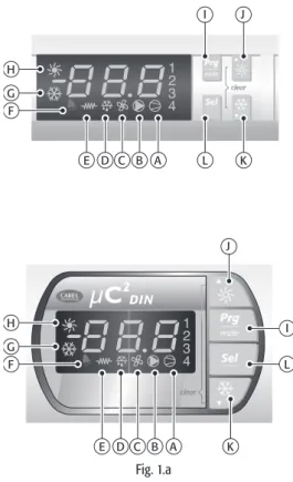
User interface
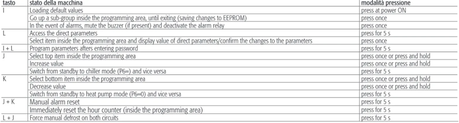
Go up the subgroup within the programming area, to exit (save changes to EEPROM) press once. In case of alarms, silence the buzzer (if present) and deactivate the alarm relay by pressing once. Select an item within the program area and display the value of direct parameters/confirm parameter changes press once. The keypad is used to set the operating values of the unit (see Parameters/Alarms - Keyboard Combinations).
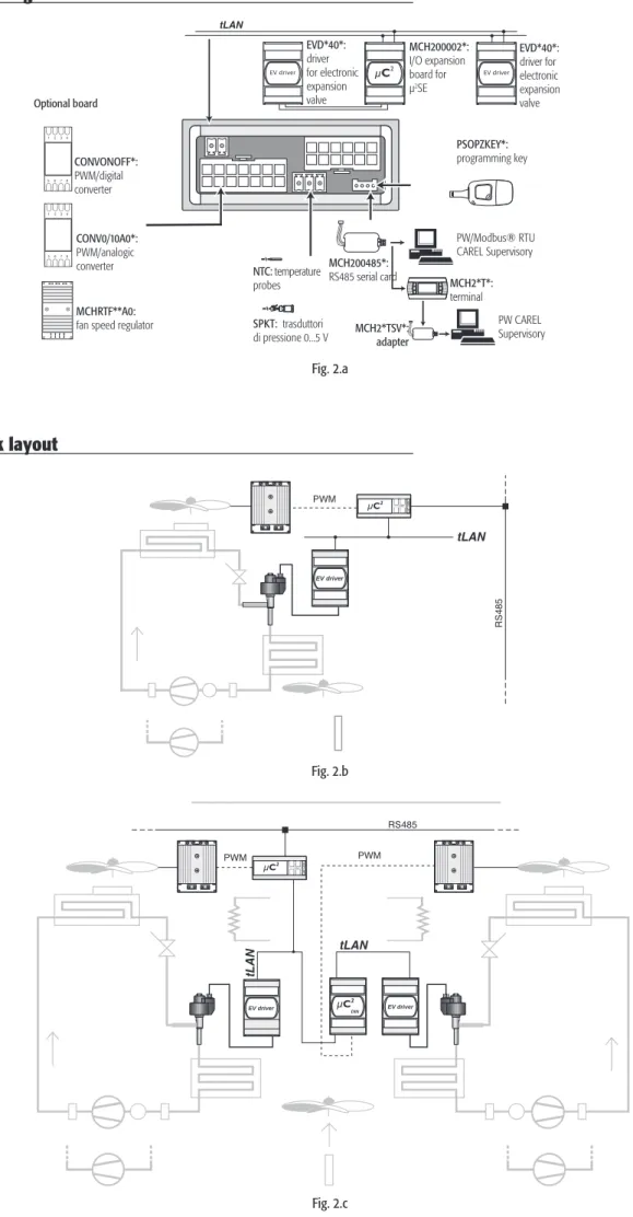
CONNeCTIONS 9
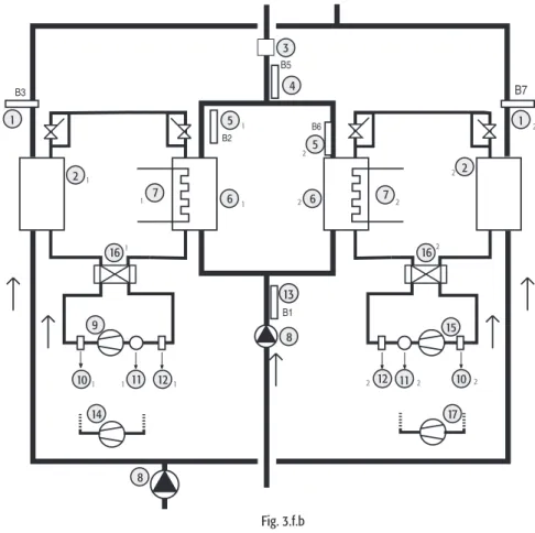
Network layout
APPlICATIONS 10
- AIR/AIR heat pump
- AIR/WATER chiller
- AIR/WATER heat pump
- WATER/WATER chiller
- WATER/WATER heat pump with reversal on gas
- WATER/WATER heat pump with reversal on water circuit
- Air-cooled condensing unit without reverse cycle
- Reverse-cycle air-cooled condensing unit
- Water-cooled condensing unit without reverse cycle
- Reverse-cycle water-cooled condensing unit
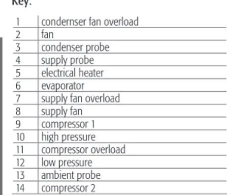
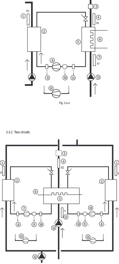
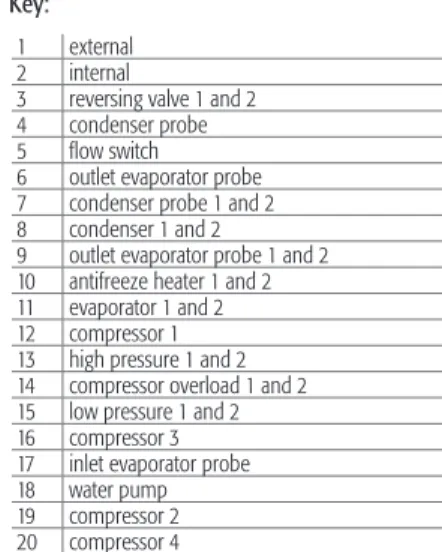
3 condenser probe 4 supply probe 5 electric heater 6 evaporator 7 supply fan overload 8 supply fan 9 compressor 1 10 high pressure 11 compressor overload 12 low pressure 13 ambient probe 14 compressor 2 15 reversing valve. 7 antifreeze heater 8 inlet evaporator probe 9 compressor 1 10 high pressure 11 compressor overload 12 low pressure 13 water pump 14 compressor 2. 6 antifreeze heater 7 inlet evaporator probe 8 compressor 1 9 high pressure 10 compressor overload 11 low pressure 12 water pump 13 compressor 2.
4 evaporator outlet probe 5 antifreeze heater 6 check valve 7 evaporator inlet probe 8 compressor 1 9 high pressure 10 compressor overload 11 low pressure 12 water pump 13 compressor 2. 5 evaporator outlet probe 6 antifreeze heater 7 evaporator 8 condenser 9 condenser probe 10 compressor 1 11 high pressure 12 compressor overload 13 low pressure 14 water pump 15 compressor 2. 1 condenser probe 2 condenser 3 antifreeze heater 4 compressor 1 5 high pressure 6 compressor overload 7 low pressure 8 compressor 2 9 check valve.
For each level, only access to parameters of the same or lower level can be set. Accessible with password 11 "Super User", allows configuration of Super User, User and Direct parameters. Accessible with password 22, it allows the configuration of parameters that can normally be set by the user (user parameters) and direct parameters, which in turn refer to options.
Accessible without a password, it is used to read the probe measurements and any data by any user, without compromising the operation of the unit.

PARAMeTeRS 25
Menu structure
Parameter tables
1= depending on the compressor (in parallel operation mode) 2= depending on the compressors in ON/OFF control 3= depending on the compressors in speed control mode. 5= water_water heat pump with reversal on gas circuit 6= water_water heat pump with reversal on water circuit 7= condensing unit. 2= Inversion valve normally open and capacity control valve normally closed 3= Inversion valve normally closed and capacity control valve normally open.

DeSCRIPTION Of The PARAMeTeRS 32
Expansion card
This unit enables the µC2 to control the second refrigerant circuit on chillers, heat pumps and condensing units with up to 4 hermetic compressors.
EVD4*: Electronic expansion valve driver
Fan speed control board (code MCHRTF*)
Fan ON/OFF control board (code CONVONOFF0)
Minimum and maximum fan speed calculation
Programming key (code PSOPZKEYA0)
RS485 serial options
Remote terminal for µC 2
This version has been designed to mount on a drilling template plate measuring 127 x 69mm with 2 4mm diameter round holes as shown in the picture. The wall mount version of the terminal requires the back of the A enclosure to be attached (Figure 7.n.b) with a standard 3-module switch box. Connect the RS485 serial line leaving the "RJ12 Power supply" to the supervisor input on µC2 using a shielded twisted pair.
Make the connection between the power supply "RJ12 Power supply" and the terminal using the telephone cable (code S90CONN002 l = 80 cm) provided. To install the remote terminal, no configuration is required on the μC2, as the terminal works with any serial address assigned to parameter H10. However, check that the µC2 is equipped with the serial interface FCSER00000 (DIN rail version) or MCH2004850 (panel version).
After about 4 s, the main screen will appear with symbols representing the status of the µC2 (Figure 7.p.b). In the event that the RS485 connection is not made correctly or the controller is turned off, the terminal will clear the screen and display the message “OFFLINE” (Figure 7.p.c). To connect the µC2 to the remote terminal MC2000TX00 while maintaining the possibility of connection to the supervisory network, the serial adapter (optional) MCH200TSV0 must be used, as shown in fig.
Unplug the telephone connector, open the cover on the 15-pin pin strip with a small pair of nippers and insert the adapter (pin strip to 4-pin plug) in the orientation shown in Fig 7.m (pin 1 on the left from the side of the triangle). Connect the RS485 network to the inverter and set the parameter H10 (serial address) of the µC2 to the desired value. C Switch off buzzer or alarm relay, if alarm active, press 1x Manual reset of alarms that are no longer active, press 5 s B Enter parameter programming mode after entering the password, press 1x A Return to a higher subgroup in the programming environment until.
Change from standby to cooling mode (P6= 0) and vice versa Press for 5 s. E Access to direct parameters: selection (as for button on µC2) Press for 5 s. Select item in the programming environment and show direct parameter values/confirm the changes of the parameter Press once F Select bottom point in the programming environment Press once or hold. Switch from standby to heat pump mode (P6= 0) and vice versa Press for 5 s D+F Instantly reset the hour counter (inside the programming environment Press for 5 s.
DIMeNSIONS 61
Software updates