In addition, the CE mark guarantees that our equipment fully complies with the requirements of the European Machinery Directive in terms of safety. EN378 Refrigeration systems and heat pumps - Safety and environmental requirements EN12735 Copper and copper alloys - Round seamless copper pipes for air conditioning. UNI EN 12735 Seamless copper pipes, round for air conditioning and refrigeration UNI EN 14276 Pressure equipment for refrigeration systems and heat pumps.
General warnings
Preservation of the documentation
Warnings regarding safety and
Product identifi cation
Description and choice of unit
Set-ups available
Confi gurator
Description of components
Cooling circuit
Hydraulic circuit
Frame and fan
Control and safety components
Electronic modu control adjustment
Accessories
Pumps kit (accessory)
The Aermec sound power value is determined based on measurements made in accordance with the ISO 9614-2 standard.
Technical data
Operational limits
Project data
Yield and absorptions different
Ethylene glycol solutions
How to interpret glycol curves
Pressure drops
Plate heat exchanger and fi lter
Electric resistance pressure drop
Total pressure drops
Sound data
Calibration of safety and control
Selection and place of installation
Positioning
Minimum technical spaces (mm)
Hydraulic circuit
Hydraulic circuit recommended
Loading the system
Emptying the system
Position of hydraulic connections
Electric connections
- Recommended electric cable section
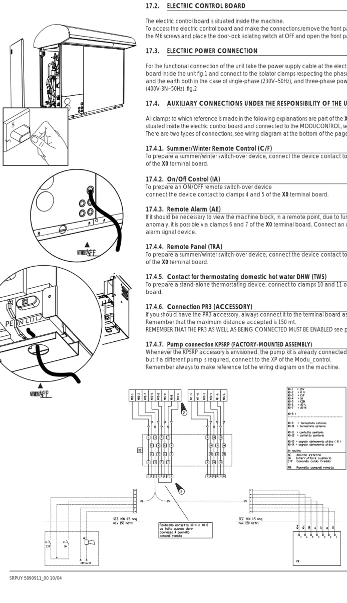
- Electric control board
- Electric power connection
- Auxiliary connections under the
To functionally connect the unit, take the power cable on the electrical control panel inside the unit, fig. 1, and connect it with the disconnecting terminals, taking into account the phase, neutral and ground, both in the case of single-phase (230V~ 50Hz) and three-phase power supply (400V-3N~50Hz). To prepare the summer/winter switching device, connect the contact of the device to terminals 3 and 5 of the connection board X0. If, due to malfunctions, it is necessary to view the machine block at a remote point, this is possible via terminals 6 and 7 of the connection board X0.
To prepare a summer/winter switch device, connect the device contact to terminals 8 and 9 of the X0 terminal board. Whenever the KPSRP accessory is provided, the pump kit is already connected to the plant, but if another pump is required, connect it to Modu_control's XP. The intervention of this alarm determines the compressor block and not the pump block, which remains active together with the ignition of the resistor if installed.
Check the tightening of the screws of the compressors and the electrical box, as well as the outer casing of the unit. We recommend that you provide a hardware book (not included, but the responsibility of the user) that allows monitoring of interventions on the device. Use the date to record the date, type of intervention performed (routine maintenance, inspections or repairs), description of the intervention, actions taken.
It provides that the disposal of the unit is carried out in accordance with the standards in force in various countries. Some parameters in the moducontrol table should be set appropriately based on the type of system in which. The display shows the index of the USER parameter and a three-character string that identifies it.
The screen shows the index of the INSTALLER parameter and a string of three characters that identifies it. This parameter indicates the standby time for reversal of the 3-way bypass valve on the DHW production system. Remove the bracket attached to the base of the compressor before closing the front panel.
Electric resistances
Electric resistances selection
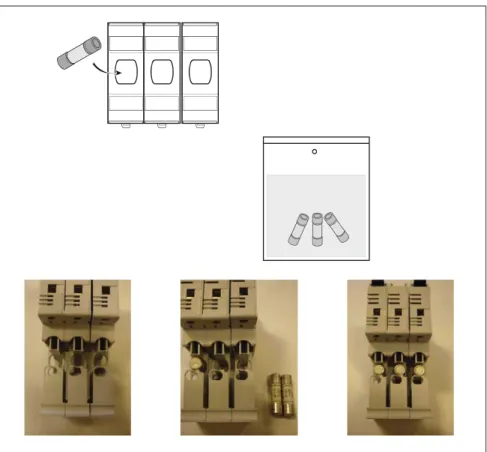
For the desired configuration of the integrating electrical resistors, insert the fuses into the clamps placed inside the electrical box of the SRP, as indicated in TAB.
Control and commissioning
Preparation for commissioning
Machine commissioning
Season changeover
Functioning features
Set point in heating mode
Compressor start-up delay
Circulation pump
Anti-freeze alarm
Water fl ow rate alarm
Maintenance
Extraordinary maintenance
Under normal conditions, they do not require technical assistance related to refrigerant gas control. Over time, gas leakage can be generated from the joints, causing refrigerant to escape and discharge the circuit, causing the appliance to malfunction. In these cases, the leakage points must be detected, repaired and the gas circuit must be refilled in accordance with the law of 28. December 1993 No. 549.
Empty and dry the entire cooling circuit using a vacuum pump connected to the low and high pressure outlet until 10 Pa is read on the vacuum gauge. Connect the refrigerant gas cylinder or a charge cylinder to the plug on the low pressure line. Operating conditions that are different from the nominal conditions can create values that are very different.
The sealing test or the search for leaks must only be carried out with R407C refrigerant gas, check with a suitable leak detector. In the cooling circuit, it is forbidden to use oxygen or acetylene or other flammable or toxic gases, because they cause explosions or poisoning. In this way, it will be easy to organize the interventions appropriately, making research and prevention of possible machine breakdowns easier.
It is forbidden to REFILL the circuit with a refrigerant gas different from the one specified.
List of controls for the guided
Radiant panels (floor, etc..) Set the parameter StC (index 3 USER menu) to the value 35 °C Fan coils or. Other applications Set the parameter StC (index 3 USER menu) to the value of 55 °C. 2) Is the external panel accessory installed (PR3). Seasonal control enabled from PR3. ON/OFF control enabled from PR3. 3) Is DHW production provided.
Presumed Set the ASA parameter (index A INSTALLER MENU) with the value (1). 4) Is a 3-way diverter valve provided in the DHW production circuit. This parameter provides the ID of the digital terminal (marked on the PCB with TRA code) to which the room thermostat used to disable compressors and integrative resistors must be connected. For further information on the operations that can be performed with user and installer parameters, refer to the unit's user manual.
Dimensions and hydraulic connections .30
Srp external installation
NOTE The lower side panel has two identical water IN/OUT (closed by polyethylene caps) and 5 holes for electrical connections. The cable gland can be eyed according to customer's choice which are used for electrical connection and the cables can also be threaded. For a more secure and hermetic connection, preferably remove the cable glands and replace them with suitable cable glands (user responsibility).
NOTE The COVE is delivered separate from the machine body and installation is the responsibility of the installer, or whoever is in charge.
Dhw storage tanks
DATI TECNICI: - CAPACITA' NOMINALE = 300 l - SUPERFICIE DI SCAMBIO = 3,8 m^2 - PRESSIONE MASSIMA DI ESERCIZIO SERBATOIO = 1,0 MPa (10 bar) - TEMPERATURA MASSIMA DI ESERCIZIO SERBATOIO = 95 °C - MASSIMA TEMPERATURA DI ESERCIZIO 1 6 bar) - TEMPERATURA MASSIMA DI ESERCIZIO DEL SERBATOIO = 110 °C -VERNICIATURA LIQUIDA IN UNA MANO CON METODO "FLOW COATING" SECONDO NORMA DIN 4753 ("BLU") -ISOLAMENTO: SCHIUMATURA POLIURETANICA DIRETTA IN COFC SCHIUMATURA IN PVC: RAL 9016 SPESSORE 0,35 mm COLLAUDO: - VERIFICA TENUTA SCAMBIATORE : CON ARIA A 6 bar (100%) - CONTROLLO TENUTA SERBATOIO: RIEMPIMENTO SERBATOIO CON ARIA A 6 bar E SUCCESSIVA DECOMPOSIZIONE IN ACQUA PER AUMENTO DOC %) PRODOTTO FINITO A TENUTA: RIEMPIMENTO SERBATOIO CON ARIA A 6 bar E SUCCESSIVA Immersione IN ACQUA PER EVIDENZIARE EVENTUALI PERDITE COMPONENTI MONTATI (100%) DIMENSIONI SERBATOIO IMBALLATO: 710X710X1755mm TOT. DATI TECNICI: - CAPACITA' NOMINALE = 400 l - SUPERFICIE DI SCAMBIO = 4,5 m^2 - PRESSIONE MASSIMA DI ESERCIZIO SERBATOIO = 1,0 MPa (10 bar) - TEMPERATURA MASSIMA DI ESERCIZIO SERBATOIO = 95 °C, C.A. 6 bar) -TEMPERATURA MASSIMA DI ESERCIZIO SULLA VASCA = 110 °C -VERNICIATURA LIQUIDA IN UNA MANO CON METODO "FLOW COATING" SECONDO NORME DIN 4753 ("BLU") -ISOLAMENTO: SCHIUMATURA POLIURETANICA DIRETTA IN COFC SCHIUMATURA IN PVC: RAL 9016 SPESSORE 0,35 mm COLLAUDO: - CONTROLLO TENUTA SCAMBIATORE: CON ARIA A 6 bar (100%) - VERIFICA TENUTA SERBATOIO: RIEMPIMENTO SERBATOIO CON ARIA A 6 bar E SUCCESSIVA DECOMPOSIZIONE IN ACQUA PER AUMENTARE DOC %) PRODOTTO FINITO SICUREZZA: RIEMPIMENTO DEL SERBATOIO CON ARIA A 6 bar E SUCCESSIVA IMMERSIONE IN ACQUA PER EVIDENZIARE EVENTUALI COMPONENTI MONTATI (100%) DIMENSIONI SERBATOIO IMBALLATO: 790X790X1700mm TOT. DATI TECNICI: - CAPACITA' NOMINALE = 500 l - SUPERFICIE DI SCAMBIO = 5,5 m^2 - PRESSIONE MASSIMA DI ESERCIZIO SERBATOIO = 1,0 MPa (10 bar) - TEMPERATURA MASSIMA DI ESERCIZIO SERBATOIO = 95 °C, C.A. 6 bar) -TEMPERATURA MASSIMA DI ESERCIZIO SULLA VASCA = 110 °C -VERNICIATURA LIQUIDA IN UNA MANO CON METODO "FLOW COATING" SECONDO NORME DIN 4753 ("BLU") -ISOLAMENTO: SCHIUMATURA POLIURETANICA DIRETTA IN COFC SCHIUMATURA IN PVC: RAL 9016 SPESSORE 0,35 mm COLLAUDO: - CONTROLLO TENUTA SCAMBIATORE: CON ARIA A 6 bar (100%) - VERIFICA TENUTA SERBATOIO: RIEMPIMENTO SERBATOIO CON ARIA A 6 bar E SUCCESSIVA DECOMPOSIZIONE IN ACQUA PER AUMENTARE DOC %) PRODOTTO FINITO SICUREZZA: RIEMPIMENTO DEL SERBATOIO CON ARIA A 6 bar E SUCCESSIVA IMMERSIONE IN ACQUA PER EVIDENZIARE EVENTUALI PERDITE COMPONENTI MONTATI (100%) DIMENSIONI SERBATOIO IMBALLATO: 790X790X1970 mm TOT.
System storage tanks
External installation
Internal installation
Installation accessories