After the air conditioner stops operating, turn off the power switch and pull out the power plug. Before working on electrical parts, discharge the capacitor. lt;Precautions during repair>. When repairing or inspecting a circuit must be done without turning off the power, be very careful not to touch live parts.
It may cause an explosion, explosion or fire when the device is used, serviced or disposed of. Correct refrigerant is specified in the manuals and on the specifications supplied with our products. We will not be held responsible for mechanical failures, system failures, device crashes or accidents caused by failure to follow instructions.
Connecting the following models to the outdoor units of the MUZ-EF∙VG/H series enables low power consumption control in standby mode. The following models can be connected to the MUZ-EF∙VG/H series after they have been connected to the MXZ series once and have been working, for example for relocation. In this case, the outdoor units of the MUZ-EF∙VG/H series will not work without a step.
REFRIGERANT SYSTEM DIAGRAM7
8-1. TIMER SHORT MODE
SERVICE FUNCTIONS8
8-2. HOW TO SET REMOTE CONTROLLER EXCLUSIVELY FOR A PARTICULAR INDOOR UNIT A maximum of 4 indoor units with wireless remote controllers can be used in a room
8-3. AUTO RESTART FUNCTION
Operation
NOTE
Before starting to set up the Wi-Fi interface, make sure that the router supports the WPA2-AES encryption setting. The end user must read and accept the Wi-Fi service terms and conditions before using this Wi-Fi interface. A router may be required to complete the connection of this Wi-Fi adapter to the Wi-Fi service.
This Wi-Fi interface will not begin transmitting any operational data from the system until the end user registers and accepts the Wi-Fi service terms and conditions. This Wi-Fi interface must not be installed and connected to any Mitsubishi Electric system that must provide critical application cooling or heating. At the time of relocation or disposal, restore the Wi-Fi interface to the factory default.
Wi-Fi interface introduction
WIRELESS REMOTE CONTROLLER
MICROPROCESSOR CONTROL9
INDOOR UNIT DISPLAY SECTION
9-2. DRY ( ) OPERATION
Coil frost prevention
9-4. HEAT ( ) OPERATION
Cold air prevention control
High pressure protection
Defrosting
9-1. COOL ( ) OPERATION
Low outside temperature operation
Indoor fan speed control
If the room temperature is higher than the set temperature, operation starts in COOL mode. If the room temperature is equal to or lower than the set temperature, operation starts in HEAT mode. COOL mode changes to HEAT mode when about 15 minutes have passed with the room temperature 1°C below the set temperature.
The HEATING mode changes to the COOLING mode after approximately 15 minutes have passed with the room temperature 1°C above the set temperature. When trying to operate 2 or more indoor units simultaneously with one outdoor unit, one for cooling and the other for heating, the operation mode of the indoor unit that operates first is selected. Other indoor units cannot work and the operation indicator light flashes as shown in the figure below.
Standard position confirmation is performed in the following cases: a) When the operation starts or ends (including timer operation). In VANE AUTO mode, the microprocessor automatically determines the angle of the vane to make the optimal distribution of room temperature. NOTE: When 2 or more indoor units are used with multiple outdoor units, even if any indoor unit turns off the thermostat, this control does not work on the indoor unit.
In the following cases, the horizontal vane returns to the closed position. a) When the STOP/OPERATE (OFF/ON) button is pressed. During COOL or DRY operation with blade angle at angle 4 or 5, when the cumulative compressor operation time exceeds 1 hour, the blade angle will automatically change to angle 1 to prevent misting. At first, the current time display on the TIME MONITOR flashes “0:00”, so set the current time correctly with the CLOCK SET button.
How to set the current time (a) Press the CLOCK setting button. b) Press the TIME SET ( and ) buttons to set the current time. Each time the FORWARD ( ) button is pressed, the set time increases by 1 minute, and each time the BACKWARD ( ) button is pressed, the set time decreases by 1 minute. Each time the FORWARD button ( ) is pressed, the set time increases by 10 minutes: each time the BACKWARD button ( ) is pressed, the set time decreases by 10 minutes.
To release the timer
Set the time of the timer with the TIME SET ( and ) buttons. a) During operation, press the OFF TIMER button ( ).
PROGRAM TIMER
9-8. WEEKLY TIMER OPERATION
- How to set the weekly timer
- Checking weekly timer setting
- How to cancel operation
- Take care of the following during servicing
- Troubleshooting procedure
- How to replace batteries
When setting the timer for more than one day of the week or one number, the button should not be pressed for each setting. Press the button to enter the weekly timer setting mode and press and hold the button for 5 seconds to clear all the weekly timer settings. When the weekly timer is ON, the day of the week will be lit, the timer setting is complete.
When all days of the week are selected to view settings and another setting is included among them, is displayed. In case of trial operation or emergency operation, use the EMERGENCY OPERATION switch on the right side of the indoor unit. Emergency operation is available if the remote control is missing or broken, or the batteries in the remote control are dead.
During test run or emergency operation, the horizontal vane operates in VANE AUTO ( ) mode. Emergency operation continues until the EMERGENCY OPERATION switch is pressed once or twice or the device receives a signal from the remote control. When the system is shut down, the compressor will not restart for 3 minutes as the 3 minute delay function kicks in to protect the compressor from overload.
TROUBLESHOOTING10
10-2. FAILURE MODE RECALL FUNCTION Outline of the function
Flow chart of failure mode recall function for the indoor/outdoor unit
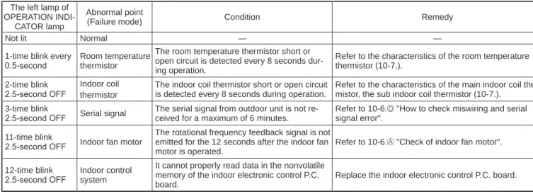
Table of indoor unit failure mode recall function The left lamp of
10-3. INSTRUCTION OF TROUBLESHOOTING
Check of the unit
Check of Wi-Fi interface (MSZ-EF∙VGKW/B/S)
10-4. TROUBLESHOOTING CHECK TABLE
10-5. TROUBLE CRITERION OF MAIN PARTS
A Check of indoor fan motor 10-6. TROUBLESHOOTING FLOW
B Check of remote controller and indoor electronic control P.C. board Check if the remote controller is exclusive for this air conditioner
C Check of indoor P.C. board and indoor fan motor
Connect the tester to the connecting wire of the fan motor connector and "-" to the connecting wire, otherwise the resistance cannot be measured properly.
D How to check miswiring and serial signal error
Is there any misconnection, poor contact or wire disconnection of the indoor/outdoor connecting wire. No (On or off). board or external electronic control P.C. Be careful of the residual voltage of the smoothing capacitor. Is there 10 to 20 V DC amplitude between internal terminal block S2 and S3. lt;Serial signal confirmation>.
If there is any fault of the indoor/outdoor connecting wire:. such as the damage of the wire, intermediate connection and/or poor contact with the terminal block, replace the indoor/.
E Electromagnetic noise enters into TV sets or radios
Indoor electronic control P.C. board
Receiver P.C. board
Switch P.C. board
10-7. TEST POINT DIAGRAM AND VOLTAGE
Removing the panel
DISASSEMBLY INSTRUCTIONS11
OPERATING PROCEDURE PHOTOS/FIGURES
Remove the indoor electrical box
- Removing the nozzle assembly
- Removing the horizontal vane motor
- Removing the indoor fan motor, the indoor coil thermistor and the line flow fan
- Removing the Wi-Fi interface
- Removing the nozzle assembly
- Removing the horizontal vane motor
- Removing the indoor fan motor, the indoor coil thermistor and the line flow fan
When attaching the line flow fan, screw the line flow fan so that there is a 4 mm gap between the right end of the line flow fan and the right wall of the box air passage (Figure 1). Screw from the line flow fan Photo 8. Screws from the left side of the heat exchanger Water section. Screws of the engine bed Power wire from. the top right side of the heat exchanger Figure 1. NOTE: Turn power OFF before disassembling.
When attaching the line flow fan, screw the line flow fan so that there is a 4 mm gap between the right end of the line flow fan and the right wall of the box air passage (Figure 1).
Fixing the indoor coil thermistor
Holder shapeClip shape
Position and procedure for mounting the clip-shape part