Liebert HPC--L
Air Cooled Chillers with Double Screw Compressors
Precision Cooling for Business--Critical Continuity
PRODUCT DOCUMENTATION
LiebertHPC--L--PD--273510--14.02.2008
Liebert HPC-- L
Liebert HPC---L---PD---273510---14.02.2008
Liebert HPC---L
The water chiller market has met in the latest years stricter and stricter challenges due to the indus- trial society evolution and to technological developments, even if it is experiencing a full maturity phase.
To meet the most different requirements, depending on the several application places, the modern water chiller must thus be highly flexible, so as to suit to the surrounding environment.
Here comes Liebert HPC---L, the innovative range of air---cooled water chillers by Emerson Net- work Power , covering a power range from 700 to 1600 kW.
Over 60 models, 4 sound emission versions, one chiller and one freecooling configurations, two types of environment---friendly refrigerants, a wide range of options and accessories --- such as economizer and electronic expansion valve, just to name two --- Liebert HPC---L can be a leader in the chiller world, both in its natural position for brand belonging --- the technological market --- and in other sectors such as high power commercial and industrial sectors.
Besides its high flexibility Liebert HPC---L --- loyal to the tradition by Emerson Network Power --- is featured by efficiencies among the highest on the market, which are more and more needed to face the challenges of energy saving and environment protection of today, as well as by the low- est sound emissions in its category, above all in the Quiet version.
Structure sturdiness and high reliability complete the features of the whole range.
Liebert HPC---L
Solutions Committed to your Business
Liebert HPC-- L
Liebert HPC---L
Contents
1 Features and Benefits
2 Model Number Description
3 Operating Range
4 Technical Data
5 Mechanical Specifications
6 Controls
7 Cooling Capacity Performance
8
Hydraulic Features and Performance Adjustment Factors
9 Sound Levels
10 Electrical Data
11 Application Considerations
12 Dimensional Data
13 Refrigerant Circuit
14 Hydraulic Circuit
The product conforms to European Union directives 98/37/CE (89/392/CEE; 91/368/CEE; 93/68/CEE), 89/336/CEE;
73/23/CEE; 97/23/CE.
Units are supplied complete with a test certificate and conformity declaration and control component list.
Liebert HPC--L units are CE marked as they comply with the European directives concerning mechanical, electrical, electromagnetic and pressure equipment safety.
The Quality Management System of Emerson Network Power S.r.l. High Performance
Air Conditioning has been approved by Lloyd's Register
Quality Assurance to the quality management system
standard ISO 9001:2000
1 Features and Benefits
1 -- 1
Liebert HPC---L---PD---273510---14.02.2008
Features and Benefits
Integration with Indoor Air Conditioners Supersaver System
A special working mode can be set up in combination withEmerson Network Power HPACindoor units to obtain the ”Supersaver’ system, that enhances the energy saving capabilities and thus optimises the SEER (Seasonal Energy Efficiency Ratio) of the system.
The information on the cooling needs of the air conditioners is available to theLiebert HPC ---Lunits, that will manage their resources (compressors and free cooling) in the most efficient way in order to save ad- ditional energy.
This solution does not require any modification, mechanical or electrical thus avoiding additional com- ponents and regulation algorithms in the units which could undermine the reliability of the system.
@ Connectivity
When the room units are equipped with the same type of control systemEmerson Network Power(Mi- croface and Hiromatic Evolution), it is possible to maximise the energy savings and improve the total op- eration management.
The solution is @connectivity, which is a highly sophisticated way to let the system components (the Air--- - Conditioners as well as theLiebert HPC ---Lunits, Chiller and Freecooling executions) talk to each other.
The @connectivity plug---in allows the setting of different working modes for different situations, such as:
D higher water temperature in low load operation (energy saving);
D lower water temperature for dehumidification (better performance);
D special ”night” Setpoint (energy saving & noise reduction);
D lower water temperature if one or more Air Conditioners fail (keep capacity in emergency situ- ations);
D . . . and much more!
To add @connectivity function to your system, it is simply necessary:
To build up an Hironet connection between the room units and theLiebert HPC ---Lunits. The network can be only 1 (if the distance and the number of units allow this) or it can be split in several networks.
Each Hironet needs to be connected to one Hirolink.
Hirolink can be connected directly to the computer where @connectivity is installed. As alternative it can be connected, with a special interface, via your company network (Local Area Network).
On @connectivity it is possible to define the rules that you want your system to respect.
It will be then up to the web capabilities to allow the view and control of your system from any PC of your Local area network (provided that @connectivity PC is connected on the LAN) or even.
If you have a connection to Internet and your system is open to external access, you will have the possibil- ity to browse and control your system via Internet.
Features and Benefits
Reliability and Low Environmental Impact Reliability
TheLiebert HPC ---Lseries is equipped with two semi---hermetic screw compressors which rep- resent state---of---the---art technology in this sec- tor. They have been designed and optimised for air---cooled water chillers within air conditioning applications.
The high volumetric efficiency ensures excellent performance of theLiebert HPC ---L units, not only at full load operation but with partial loads too, thanks to the continuous capacity control and to the sliding valves, modifying the delivery gas
outlet clearance. Extremely low noise operation and the absence of vibrations aid the installation of the unit in city sites requiring strict noise limits. The wide operating range, bearing lubrication, component oversizing, absence of vibrations and few moving parts, together with the resistance to liquid slugging and compressor electronic control integrated with the machine microprocessor enhance the well--- - known characteristics of operating reliability and long life typical of this compressors type.
Liebert HPC ---Lwith two independent refrigerating circuits, two electric boards with independent sup- plies (each one interlocked with its own refrigerating circuit), two microprocessor boards --- each one in- stalled on its electric control board and even operating independently of each other --- features the highe- st inner redundancy and thus the highest system reliability.
AllLiebert HPC ---Lunits are run tested at the factory before shipment.
Fewer moving parts
Unlike reciprocating compressors, screw compressors do not have pistons, connecting rods, suction and discharge valves or a mechan- ical oil pump. Fewer moving parts lead to greater reliability and a longer life.
High outdoor temperature
The oversizing of heat axchangers and the wide operating range of the screw compressors permit the use of Liebert HPC ---L units in high temperature environments as well, up to 46ûC at 100% full load.
In the version with R407C, only, the
device HTD (High Temperature Device), keeping the oil temperature within a safe range, allows each compressor to operate up to its limits without affecting either its reliability or its internal components (bearings).
In all versions, both with R407C and R134a, if the limits are exceeded, the microprocessor reduces the load of the compressor to 50%, thus allowing continuous operation.
Continuous capacity control
Precise and stable control of the supply water temperature over the complete range of operating condi- tions is granting by the continuous capacity control. As the demand for load increases or decreases the compressor sliding valves modulate the capacity to match the required cooling load. This leads to a drastic reduction of cycling rates in comparison with a step capacity control and therefore, higher reliabil- ity.
80,000 70,000 60,000 50,000 40,000 30,000 20,000 10,000 0
-6 -4 -2 0 2 4 6 8 10 12 14 16 18 20 22 24 26 28 30 32 Outdoor temperature (oC)
AnnualPowerconsumption(kWh)
VENICE
HAMBURG 80,000
70,000 60,000 50,000 40,000 30,000 20,000 10,000 0
Outdoor temperature (oC)
-18 -16 -14 -12 -10 -8 -6 -4 -2 0 2 4 6 8 10 12 14 16 18 20 22 24 26 28 30 32
AnnualPowerconsumption(kWh)
Annual energy consumption (Chiller)
Annual energy consumption, chiller plus free cooling module
Features and Benefits
1 -- 3
Liebert HPC---L---PD---273510---14.02.2008
Resistance to liquid slugging
The robust design of the screw compressors can bear/withstand liquid coolant quantities in suction that would severely damage the valves, the connecting rods and the cylinders of the reciprocating compres- sors.
Start---up management
The specific features ofLiebert HPC ---Lscrew compressors and the integrated microprocessor control functions permit unloaded start---up management, with pressure equalisation, thus reducing stress and enhancing the overall reliability.
Unequalled efficiency and energy saving
The use of semi---hermetic screw compressors of the latest generation; shell and tube evaporators selec- ted for R134a and R407C application; aerodynamic profiled blade fans with high efficiency nozzles and continuous speed regulation; large surface W---shaped condenser coils ensure the achievement of un- equalled efficiency figures.
Freecooling module
The execution with built---in free cooling module, allows Liebert HPC ---Lto take advantage of low outdoor air temperatures in the wa- ter cooling process in order to save energy, by avoiding compressors running,besidesincreasingsignifi- cantly the compressor life.
A three---way valve arrangement permits the coolant to be diverted via the additional heat exchangers before being fed into the cooling evaporator.
This means that even if the outside ambient temperature is not low enough to provide the complete cooling load, a significant contribu- tion to the running costs of the sy- stem can be made whenever the ambient temperatures falls below the coolant inlet temperature.
Reduced space requirements in comparison with a conventional chiller plus a dry---cooler, are ob- tained through the freecooling exe- cution’s compact design and the reduction of the compressors working hours offers exceptional saving both in the long and short term.
The different strategies adopted by the proprietary microprocessor control in managing the various com- ponents, fans --- compressors --- regulation valves, and operating modes, mechanical and/or free cool- ing, together with the compressors’ continuous partialisation ensure typical energy savings greater than 30%.
For specific applications and requirements, where the glycol mixture can’t be used and circulated inside the building,Emerson Network Powerhas developed a dedicated Freecooling version, defined as “No Glycol, Freecooling”, that border the glycol fluid inside the external unit only.
In the No Glycol Freecooling version, a plate heat exchanger is positioned between the glycol fluid of the freecooling coils and the water of the evaporator preventing from the circulation of the glycol in the user hydraulic circuit. The parts and components of the chiller exposed to the external environment involved by the water flow are protected from potential frost by insulation, the heat load of the user circuit and by
Features and Benefits
the electrical heating driven by the microprocessor control.
The plate exchanger oversizing, the optimized flow between such exchangers thanks to the use of high efficiency pumps, the operating logics managed by the microprocessor control with the same strategies of increased efficiency and reliability research of the standard freecooling versions enable a min. de- crease in the freecooling performance while advantageously recovering energy in this No Glycol version freecooling version, too.
The graph below compares the cooling performance of the two freecooling solutions for the machine model FL4092; Z.E.T. means “Zero Equivalent Temperature”, namely the temperature of external air at which the nominal mechanical cooling capacity (i.e. developed in standard summer operating condi- tions) is obtained from the freecooling system (winter cooling capacity with compressors off).
0 200 400 600 800 1000 1200 1400
-7,5 -5 -2,5 0 2,5 5 7,5 10 12,5 15 17,5
Z.E.T.
Freecooling capacity Freecooling No Glycol capacity
Freecoolingcapacity(kW)
External air (_C)
Freecooling performance comparison (FL4 092)
Features and Benefits
1 -- 5
Liebert HPC---L---PD---273510---14.02.2008
Seasonal efficiency
The freecooling execution finds its best application in combination with the Supersaver system which regulates the coolant temperatures according to the variation of the thermal load, increasing the num- bers of hours during which free cooling is possible.
The percentage of energy saving can thus be greater than 35%.
Annual power consumption. Comparison among the systems:
120
100
40
60
40
20
0
Energyconsumption(MWh)
Jan Feb Mar Apr May Jun Jul Aug Sep Oct Nov Dec
Traditional Chiller Freecooling execution
- Freecooling execution + Supersaver
Economiser circuit
The operation with economizer is a convenient and efficient method to increase the cooling capacity and the COP. This device is particular- ly advisable for the conditioning applications where the condensing temperatures are high or medium.
By this operation system, the liquid refrigerant is cooled by a heat exchanger (sub---cooler).
When a sub---cooler is used, some of the refri- gerant mass (ECO flow rate) is separated from the condenser mass after the condenser (4).
This ECO mass is thus expanded at an inter- mediate pressure (t ms). The ECO mass eva- porates inside the sub---cooler and enters the compressor through the economizer opening.
The evaporator mass flow rate is sub---cooled by the exchanger at a lower liquid temperature (4u). The intermediate pressure at the econo- mizer changes depending on the type of com- pressor, on the operating conditions (evapora- tions and condensation temperatures) and on the ECO flow rate. The additional sub---cooling of the liquid involves a significant increase of the cooling capacity. From certain operating conditions, the electric absorption by the com- pressor increases less proportionally than the cooling capacity (improving the machine effi- ciency), as the compression process occurs at a better efficiency level due to the positive con- tribution of the fresh gas portion sucked throu-
Chiller Load
User Load
Fluctuation with steps capacity control
Outletwater temperature (°C)
%Coolingcapacity
Time 100
75
98 76 5
98 76 5 100 75
Time
Outletwater temperature (°C)
%Coolingcapacity Chiller Load User Load
100
75
98 76 5
Stability with stepless capacity control 98 76 5 100 75
Features and Benefits
gh the ECO opening.
A further feature of the economizer circuit in theLiebert HPC ---Lunits is the slide valve for choking the compressor, equipped with an integrated economizer channel; this ensure the above described bene- fits, due to the additional sub---cooling, independently of the machine load conditions and thus of the position of the slide valve for the compressor choking.
Efficient control and adjustment
The different strategies of the micropro- cessor control by Emerson Network Powerfor the compressors --- capacity adjustment valves with continuous mod- ulation and different operating modes (economizer, expansion with electronic valve) --- ensure energy saving typically over 20%.
The cooling capacity can be changed and modulated continuously thanks to the microprocessor control of the cho- king slide valve for the compressor capa- city. Each unit is equipped with a variable power control without limits from 100%
up to 25%. This modulation enables the compressor to perfectly meet the buil- ding---cooling load without any change in the outlet temperature from the evapora- tor. This change in the cooled water tem- perature is avoided only thanks to a ste- pless control, such as the one offered by Emerson Network Power. Indeed, with a step capacity control with partial loads, each power step would be too high or too low when compared to the building--- - cooling load, so loosing water tempera- ture control.
Thus, the energy costs for the chiller are decreased, above all under conditions of partial load featuring the chiller operation most of the time.
Seasonal efficiency: IPLV---ESEER efficiency ratios
Liebert HPC ---Lfeatures excellent performance under partial loads. The loads of the air conditioning sy- stems in the standard operating conditions are remarkably lower than the max. rated load conditions for the chiller selection.
Thus, chillers seldom work under full load. TheLiebert HPC ---Lchillers can offer significant operation savings.
The operation of the chillers under partial load is usually associated with reduced air temperatures in the condenser and reduced room temperatures.
With the operation under partial load, the heat to be disposed is less than the one under full load. Further, the operation under partial load is typically associated with reduced outdoor temperatures that enable the best performance of the unit.
The operation under partial load associated with reduced room temperatures ensures better performan- ce and efficiency by the chiller. IPLV (Integrated Part Load Value) is a method for measuring the total chil- ler performance in a defined range of operating conditions under partial load. This method has been stu- died by ARI and is included in the standard ARI 550/590---98. As most of the conditioning systems operate for most of the time at a load lower than the max. rated one, IPLV is an excellent method to com- pare the chiller efficiency under similar conditions.
Features and Benefits
1 -- 7
Liebert HPC---L---PD---273510---14.02.2008
The formula to calculate IPLV is:
IPLV = 0.01A + 0.42B + 0.45C + 0.12D Where:
A= EER at 100%, load point at 35.0°C condenser air inlet B= EER at 75%, load point at 26.7°C
C= EER at 50%, load point at 18.3°C D= EER at 25%, load point at 12.8°C
An alternative seasonal efficiency ratio has been defined for Europe, which is more suitable for the load conditions, the outdoor air temperatures and the building principles typical of European countries. It is defined by the acronym ESEER (European Seasonal Energy Efficiency Ratio), as specified here below:
ESEER = 0.03A + 0.33B + 0.41C + 0.23D Where:
A= EER at 100%, load point at 35°C condenser air inlet B= EER at 75%, load point at 30.0°C
C= EER at 50%, load point at 25.0°C D= EER at 25%, load point at 20.0°C
Such ratios are really useful to calculate the energy consumption, when the load distribution required by the chiller in one year of operation follows the same percentage subdivisions considered in the above mentioned formulas.
Absorbed energy = Required energy / Efficiency ratio Tab. 1a --- Efficiency ratios
HPC---L
Model Size EER IPLV ESEER Model Size EER IPLV ESEER
CA7
081 2.67 4.20 3.70
CA4
069 3.31 4.33 3.99
087 2.59 4.10 3.60 075 3.22 4.45 4.06
093 2.57 3.97 3.51 081 3.16 4.58 4.15
100 2.49 4.01 3.53 087 3.08 4.39 3.96
107 2.62 4.20 3.71 093 3.04 4.09 3.75
115 2.54 4.06 3.57 100 3.00 4.26 3.85
122 2.67 4.03 3.59 107 3.15 4.46 4.04
131 2.85 4.18 3.75 --- --- --- ---
140 2.78 4.24 3.78 --- --- --- ---
CB7
081 2.59 4.27 3.72
CB4
069 3.28 4.49 4.09
087 2.49 4.12 3.59 075 3.18 4.59 4.15
093 2.48 4.01 3.51 081 3.09 4.73 4.23
100 2.38 4.07 3.54 087 3.00 4.46 4.02
107 2.52 4.24 3.73 093 2.97 4.19 3.80
115 2.44 4.09 3.57 100 3.93 4.35 3.92
122 2.58 4.07 3.60 107 3.10 4.61 4.14
131 2.79 4.28 3.82 --- --- --- ---
140 2.71 4.33 3.84 --- --- --- ---
CL7
080 2.77 4.40 3.88
CL4
068 3.29 4.56 4.16
086 2.68 4.27 3.77 074 3.17 4.67 4.20
092 2.79 4.29 3.82 080 3.28 4.82 4.36
099 2.70 4.35 3.85 086 3.19 4.58 4.15
106 2.62 4.43 3.88 092 3.29 4.40 4.05
114 2.54 4.24 3.72 099 3.26 4.58 4.18
121 2.81 4.34 3.85 106 3.24 4.81 4.33
130 2.72 4.37 3.86 --- --- --- ---
139 2.63 4.40 3.88 --- --- --- ---
CQ7
080 2.46 4.31 3.71
CQ4
068 3.05 4.59 4.13
086 2.36 4.14 3.57 074 2.89 4.63 4.15
092 2.49 4.21 3.66 080 3.03 4.88 4.35
099 2.38 4.25 3.67 086 2.93 4.57 4.13
106 2.26 4.31 3.70 092 3.07 4.46 4.05
114 2.17 4.09 3.49 099 3.00 4.60 4.16
121 2.50 4.22 3.67 106 2.95 4.79 4.29
EER(Energy Efficiency Ratio) IPLV(Integrated Part Load Value)
ESEER(European Seasonal Energy Efficiency Ratio)
Features and Benefits
Low sound emission
TheLiebert HPC ---Lseries is characterised by unrivalled low sound emissions, in particular the models of the version Quiet.
A sound---proofed compressors enclosure, ”Muffler”---type pulsation dampers integrated in the com- pressor oil separator, compressor fastening on insulating/anti---vibration supports, inlet and outlet hoses, fans and speed adjusters specifically designed to reduce sound emission lead to these superior results.
All units are equipped with a modulating fans speed control; controlled by a special algorithm which, while optimising the compressors management, enables to keep the fan speed always to the minimum.
Even lower sound emission levels can be obtained with the EC fans (with integrated electronic switching motor), above all in low speed operation.
B- Base version L- Low noise version Q- Quiet version
Models
Liebert HPC-Lseries sound emissions at 1 m distance
068 074 080 086 092 099 106 114 121 130 139
069 075 081 087 093 100 107 115 122 131 140
85
80
75
70
65
60
55
dB(A)
B- FC Base version L- FC Low noise version Q- FC Quiet version
Tab. 1b --- Sound levels
Models HPC---L (Chiller) HPC---L (Freecooling)
“B”version “L”version “Q”version “B”version “L”version “Q”version
068 --- 069 79.5 73.0 65.0 80.0 73.0 65.5
074 --- 075 79.5 73.0 65.0 80.0 73.0 65.5
080 --- 081 79.5 73.5 65.5 80.0 73.0 65.5
086 --- 087 79.5 73.5 65.5 80.0 74.0 66.0
092 --- 093 80.0 74.0 66.0 80.0 74.0 66.0
099 --- 100 80.0 74.0 66.0 81.0 74.0 66.0
106 --- 107 80.5 74.0 66.0 81.0 74.0 66.0
114 --- 115 80.5 74.0 66.0 81.0 75.0 67.0
121 --- 122 81.0 75.0 67.0 81.0 75.0 67.0
130 --- 131 82.0 75.0 --- --- --- ---
139 --- 140 82.0 75.0 --- --- --- ---
The unit sound level in the version ”B” and in the version ”L” is lowered by 3 dB(A) in standard operating conditions with water 12/7ûC at the evaporator and outdoor air less than 30ûC by special suitable meas- ures, such as:
D better sound insulation of the compressor compartment;
D automatic fan speed reduction with standard adjustment with phase cutoff (TRIAC) for the ”B” ver- sions;
D automatic fan speed reduction with inverter adjustment for the ”L” versions.
2 Model Number Description
2 -- 1
Liebert HPC---L---PD---273510---14.02.2008
Model Number Description
Model Nomenclature / Digit Numbers
1 2 3 4 5 6 7 8 9 10 11 12 13 14 15 16 17 18
B 4 0 6
C 9
Cooling Capacity
Cooling capacity (x 10 = kW) Refrigerant
4= R134a 7= R407C Versions
A= Efficiency ”class A”
B= Base L= Low noise Q= Quiet Specification
C= Air cooled Chiller
Liebert HPC---L
Digits 1, 2, 3, 4, 5, 6 --- Base unit Base unit main features
D Structure and bearing base in galvanized steel sheet sections, with powder---painting and suitable thickness
D Two indipendent refrigeration circuits
D Semihermetic screw compressors with continuous capacity control
D Shell & Tube evaporators with direct expansion and independent circuit on the refrigerant side for each compressor
D Axial fans with modulating speed control
D Condensing coils with copper pipes and aluminum fins
D International approval 97/23 EC --- PED
D Microface board / Display control interlocked to each electric board
D Double electric panel CE compliant and complete with safety equipments, fan motors protection, fuses and protection thermal relays for compressors, power supply 400 V / 3 Ph / 50 Hz (RST + PE)
D Main switch on each electric board
D Antiscratch plastic film packaging
D Colour Ral 7032 “Grey”
Digit 7 --- Electronic expansion valve (EEV) 0= Standard mechanic valve
1= Electronic valve
Digit 8 --- Compressor suction shut---off valve 0= None
1= With shut---off valve
Digit 9 --- Refrigerant gauges 0= None
1= With HP/LP gauges
Digit 10 --- Economiser (ECO) / Liquid injection 0= No ECO / no liquid injection
1= With ECO
2= With liquid injection
Digit 11 --- Fan speed control 1= TRIAC control
2= Inverter control 3= EC---Fan
Digit 12 --- Pumps group / Hydraulic Kit 0= No pumps / no hydraulic Kit
1= No pumps / with hydraulic Kit
2= 2 standard head pumps / with hydraulic Kit 3= 2 high head pumps / with hydraulic Kit
4= 2 pumps (1 with inverter), standard head / with hyd. Kit 5= 2 pumps (1 with inverter), high head / with hyd. Kit Digit 13 --- 20 % heat recovery
0= None
1= 20 % heat recovery
Digit 14 --- Electric panel options 0= None
1= With electric heaters 2= With energy meter
3= With electric heaters and energy meter Digit 15 --- Evaporator electric heaters 0= None
1= With electric heaters only evaporator
2= With evaporator electric heaters, pumps and pipes Digit 16 --- Compressor power factor capacitors 0= None
1= With compressor power factor capacitors
Digit 17 --- Condensing coil filter / Protection grid 0= None
1= With condensing coil filter 2= With protection grids
3= With condensing coil filters and protection grids Digit 18 --- Special requests
0= None X= As Specified
Model Number Description
Model Nomenclature / Digit Numbers
1 2 3 4 5 6 7 8 9 10 11 12 13 14 15 16 17 18
B 4 0 6
F 9
Cooling Capacity
Cooling capacity (x 10 = kW) Refrigerant
4= R134a 7= R407C Versions
A= Efficiency ”class A”
B= Base L= Low noise Q= Quiet Specification
F= Freecooling Chiller
Liebert HPC---L
Digits 1, 2, 3, 4, 5, 6 --- Base unit Base unit main features
D Structure and bearing base in galvanized steel sheet sections, with powder---painting and suitable thickness
D Two indipendent refrigeration circuits
D Semihermetic screw compressors with continuous capacity control
D Shell & Tube evaporators with direct expansion and independent circuit on the refrigerant side for each compressor
D Axial fans with modulating speed control
D Freecooling coils with copper pipes and aluminum fins
D Condensing coils with copper pipes and aluminum fins
D International approval 97/23 EC --- PED
D Microface board / Display control interlocked to each electric board
D Double electric panel CE compliant and complete with safety equipments, fan motors protection, fuses and protection thermal relays for compressors, power supply 400 V / 3 Ph / 50 Hz (RST + PE)
D Main switch on each electric board
D Antiscratch plastic film packaging
D Colour Ral 7032 “Grey”
Digit 7 --- Electronic expansion valve (EEV) 0= Standard mechanic valve
1= Electronic valve
Digit 8 --- Compressor suction shut---off valve 0= None
1= With shut---off valve
Digit 9 --- Refrigerant gauges 0= None
1= With HP/LP gauges
Digit 10 --- Economiser (ECO) / Liquid injection 0= No ECO / no liquid injection
1= With ECO
2= With liquid injection
Digit 11 --- Fan speed control 1= TRIAC control
2= Inverter control 3= EC---Fan
Digit 12 --- Pumps group / Hydraulic Kit Complete freecooling version
0= No pumps / no hydraulic Kit 1= No pumps / with hydraulic Kit
2= 2 standard head pumps / with hydraulic Kit 3= 2 high head pumps / with hydraulic Kit
4= 2 pumps (1 with inverter), standard head / with hyd. Kit 5= 2 pumps (1 with inverter), high head / with hyd. Kit No---glycol freecooling version
A= No pumps / no hydraulic Kit B= No pumps / with hydraulic Kit
C= 2 standard head pumps / with hydraulic Kit D= 2 high head pumps / with hydraulic Kit
E= 2 pumps (1 with inverter), standard headF/ with hyd. Kit F= 2 pumps (1 with inverter), high head / with hyd. Kit Digit 13 --- 20 % heat recovery
0= None
1= 20 % heat recovery
Digit 14 --- Electric panel options 0= None
1= With electric heaters 2= With energy meter
3= With electric heaters and energy meter Digit 15 --- Evaporator electric heaters 0= None
1= With electric heaters only evaporator
2= With evaporator electric heaters, pumps and pipes Digit 16 --- Compressor power factor capacitors 0= None
1= With compressor power factor capacitors
Digit 17 --- Condensing coil filter / Protection grid 0= None
1= With condensing coil filter 2= With protection grids
3= With condensing coil filters and protection grids Digit 18 --- Special requests
0= None X= As Specified
3 Operating Range
3 -- 1
Liebert HPC---L---PD---273510---14.02.2008
Operating Range
Working Limits
Minimum temperature of outdoor air entering condenser coils (with standard operating unit):
---25ûC for freecooling models;
---10ûC for Chiller models.
Maximum outdoor air temperature is in relation to each model, as indicated in the following tables. In any case outdoor temperatures over 46ûC are not admitted; such limits are determined by electrical and electronic components fitted on units. Maximum flow rates are indicated in the following tables.
Higher flow values may cause corrosions and vibrations inside the shell and tube heat exchanger.
The Minimum water flow allowed corresponds to a maximum temperature difference of 8ûC. More extreme operating conditions would active safety devices and the unit would be stopped.
Outlet water temperature from 4 to 15ûC.
The maximum allowed water return temperature when the unit is in full operation is 20 ûC; return temperatures in excess of 20ûC are allowed only during start---up.
The maximum glycol percentage permitted is 50% (35% with standard pump sets fitted)
The minimum glycol percentage necessary is in relation to the minimum ambient air temperature conditions referred to the place of installation.
The maximum hydraulic working pressure is 6 Barg (Safety valve setting is 5 Barg with the optional hydraulic kit).
Nominal power supply tolerance: 400V+/---10%; max. voltage drop: 3%.
See operation range Table in which each model’s limits are indicated; for different values ask your agent.
Unit storage conditions:
D Between ---20ûC and + 45ûC for all models.
Operating Range
Tab. 3a --- Operating range --- HPC ---L R407C
Models: CA7 081 087 093 100 107 115 122 131 140
Operating range
Max. outdoor temperature(1) Max. outdoor temperature(2) Max. water flow
°C
°C m3/h
41.0 44.5 234
41/39 44.5/42.5
234
39.5 43.0 234
39.5/37.5 43/41
234
39.5 43.0 258
39.5/37.5 43/41
258
40.0 43.5 316
43/38 46.5/38
316
38.0 38.0 316 Safety devices settings
High pressure switch(1) High pressure switch(2) High pressure safety valve Low pressure switch Low pressure safety valve
bar bar bar bar bar
24 26 29 2.8 17.3
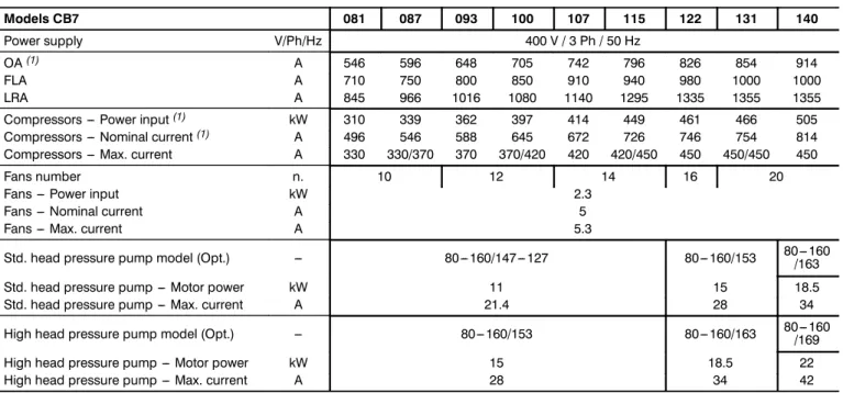
Models: CB7 081 087 093 100 107 115 122 131 140
Operating range
Max. outdoor temperature(1) Max. outdoor temperature(2) Max. water flow
°C
°C m3/h
40.0 43.5 234
40/38 43.5/41.5
234
38.5 42.0 234
38.5/36.5 42/40
234
38.5 42.0 258
38.5/36.5 42/40
258
39.0 42.5 316
42.5/37 46/37
316
37.0 37.0 316 Safety devices settings
High pressure switch(1) High pressure switch(2) High pressure safety valve Low pressure switch Low pressure safety valve
bar bar bar bar bar
24 26 29 2.8 17.3
Models: CL7 080 086 092 099 106 114 121 130 139
Operating range
Max. outdoor temperature(1) Max. outdoor temperature(2) Max. water flow
°C
°C m3/h
42.0 45.5 234
42/40 45.5/43.5
234
42.0 45.5 234
42/40 45.5/43.5
234
39.0 42.5 258
39/37 42.5/40.5
258
41.0 44.5 316
41.0/35.5 44.5/35.5
316
35.5 35.5 316 Safety devices settings
High pressure switch(1) High pressure switch(2) High pressure safety valve Low pressure switch Low pressure safety valve
bar bar bar bar bar
24 26 29 2.8 17.3
Models: CQ7 080 086 092 099 106 114 121
Operating range
Max. outdoor temperature(1) Max. outdoor temperature(2) Max. water flow
°C
°C m3/h
38 41.5 234
38/36 41.5/39.5
234
38 41.5
234
38/36 41.5/39.5
234
35 38.5 258
35/33 38.5/36.5
258
37 40.5 316 Safety devices settings
High pressure switch(1) High pressure switch(2) High pressure safety valve Low pressure switch Low pressure safety valve
bar bar bar bar bar
24 26 29 2.8 17.3
(1) --- With nominal air flow; water outlet temperature 7ûC; full load; R407C refrigerant; standard version and with economiser option.
(2) --- With nominal air flow; water outlet temperature 7ûC; full load; R407C refrigerant; version with liquid injection option.
Notes:
The units are equipped with automatic capacity reduction system to avoid the machine lock before reaching the indicated outdoor air temperature max. limits.
In the units with economizer option, such device is disabled before reaching the indicated outdoor air temperature max. limits.
In the units with asymmetrical compressors, the indicated outdoor air temperature max. limit are referred to each refrigerating circuit.
Operating Range
3 -- 3
Liebert HPC---L---PD---273510---14.02.2008
Tab. 3b --- Operating range --- HPC ---L R134a
Models: CA4 069 075 081 087 093 100 107
Operating range
Max. outdoor temperature(1) Max. water flow
°C
m3/h 52.5
170 52.5/49.5
170 49.5
230 49.5/47
230 49.0
230 49/46
230 48.5
256 Safety devices settings
High pressure switch(1) High pressure safety valve Low pressure switch Low pressure safety valve
bar bar bar bar
18 20 1.1 12
Models: CB4 069 075 081 087 093 100 107
Operating range
Max. outdoor temperature(1) Max. water flow
°C
m3/h 51.5
170 51.5/48
170 48.0
230 48/45.5
230 47.5
230 47.5/44.5
230 47.5
256 Safety devices settings
High pressure switch(1) High pressure safety valve Low pressure switch Low pressure safety valve
bar bar bar bar
18 20 1.1 12
Models: CL4 068 074 080 086 092 099 106
Operating range
Max. outdoor temperature(1) Max. water flow
°C
m3/h 51.0
170 51/48
170 50.5
230 50.5/48
230 51.5
230 51.5/48.5
230 48.5
256 Safety devices settings
High pressure switch(1) High pressure safety valve Low pressure switch Low pressure safety valve
bar bar bar bar
18 20 1.1 12
Models: CQ4 068 074 080 086 092 099 106
Operating range
Max. outdoor temperature(1) Max. water flow
°C m3/h
47.5 170
47.5/44.5 170
46.5 230
46.5/44.5 230
48.0 230
48/45 230
44.5 256 Safety devices settings
High pressure switch(1) High pressure safety valve Low pressure switch Low pressure safety valve
bar bar bar bar
18 20 1.1 12
(1) --- With nominal air flow; water outlet temperature 7ûC; full load; R134a refrigerant; standard version and with economiser option.
For indicated temperatures over 46ûC, the limits are to be referred to special units in tropicalized version.
Notes:
The units are equipped with automatic capacity reduction system to avoid the machine lock before reaching the indicated outdoor air temperature max. limits.
In the units with economizer option, such device is disabled before reaching the indicated outdoor air temperature max. limits.
In the units with asymmetrical compressors, the indicated outdoor air temperature max. limit are referred to each refrigerating circuit.
Operating Range
Tab. 3c --- Operating range --- HPC ---L with freecooling R407C
Models: FA7 081 087 093 100 107 115 122
Operating range
Max. outdoor temperature(1) Max. outdoor temperature(2) Max. water flow
°C
°C m3/h
38.541.5 234
38,5/36 41,5/39 234
36.039.0 234
41/38,5 44/41,5 234
38.541.5 258
38,5/36 41,5/39 258
36.039.0 316 Safety devices settings
High pressure switch(1) High pressure switch(2) High pressure safety valve Low pressure switch Low pressure safety valve
barbar barbar bar
2426 2.829 17.3
Models: FB7 081 087 093 100 107 115 122
Operating range
Max. outdoor temperature(1) Max. outdoor temperature(2) Max. water flow
°C
°C m3/h
37.540.5 234
37,5/35 40,5/38 234
35.038.0 234
40/37,5 43/40,5 234
37.540.5 258
37,5/35 40,5/38 258
35.038.0 316 Safety devices settings
High pressure switch(1) High pressure switch(2) High pressure safety valve Low pressure switch Low pressure safety valve
barbar barbar bar
2426 2.829 17.3
Models: FL7 080 086 092 099 106 114 121
Operating range
Max. outdoor temperature(1) Max. outdoor temperature(2) Max. water flow
°C
°C m3/h
36.038.5 234
41/38,5 43,5/41 234
38.541.0 234
38,5/36 41/38,5 234
36.038.5 258
40/37,5 42,5/40 258
37.540.0 316 Safety devices settings
High pressure switch(1) High pressure switch(2) High pressure safety valve Low pressure switch Low pressure safety valve
barbar barbar bar
2426 2.829 17.3
Models: FQ7 080 086 092 099 106 114 121
Operating range
Max. outdoor temperature(2) Max. water flow
°C
m3/h 35.0
234 39,5/37
234 37.0
234 37/35
234 35.0
258 38,5/36
258 36.0
316 Safety devices settings
High pressure switch(1) High pressure switch(2) High pressure safety valve Low pressure switch Low pressure safety valve
barbar barbar bar
2426 2.829 17.3
(1) --- With nominal air flow; fluid outlet temperature 10°C; full load; R407C refrigerant; standard version and with economiser option.
(2) --- With nominal air flow; fluid outlet temperature 10°C; full load; R407C refrigerant; version with liquid injection option.
Notes:
The units are equipped with automatic capacity reduction system to avoid the machine lock before reaching the indicated outdoor air temperature max. limits.
In the units with economizer option, such device is disabled before reaching the indicated outdoor air temperature max. limits.
In the units with asymmetrical compressors, the indicated outdoor air temperature max. limit are referred to each refrigerating circuit.
Operating Range
3 -- 5
Liebert HPC---L---PD---273510---14.02.2008
Tab. 3d --- Operating range --- HPC ---L with freecooling R134a
Models: FA4 069 075 081 087 093 100 107
Operating range
Max. outdoor temperature(1) Max. water flow
°C
m3/h 49.0
170 49/46,5
170 46.5
230 46,5/44
230 44.0
230 50/47,5
230 47.5
256 Safety devices settings
High pressure switch(1) High pressure safety valve Low pressure switch Low pressure safety valve
barbar barbar
1820 1.112
Models: FB4 069 075 081 087 093 100 107
Operating range
Max. outdoor temperature(1) Max. water flow
°C
m3/h 48.0
170 48/45,5
170 45.5
230 45,5/43
230 43.0
230 49/46,5
230 46.5
256 Safety devices settings
High pressure switch(1) High pressure safety valve Low pressure switch Low pressure safety valve
barbar barbar
1820 1.112
Models: FL4 068 074 080 086 092 099 106
Operating range
Max. outdoor temperature(1) Max. water flow
°C
m3/h 46.0
170 46/43,5
170 43.5
230 50/47,5
230 47.5
230 47,5/44,5
230 44.5
256 Safety devices settings
High pressure switch(1) High pressure safety valve Low pressure switch Low pressure safety valve
barbar barbar
1820 1.112
Models: FQ4 068 074 080 086 092 099 106
Operating range
Max. outdoor temperature(1) Max. water flow
°C
m3/h 42.0
170 42/39,5
170 39.5
230 46/43,5
230 43.5
230 43,5/40,5
230 40.5
256 Safety devices settings
High pressure switch(1) High pressure safety valve Low pressure switch Low pressure safety valve
barbar barbar
1820 1.112
(1) --- With nominal air flow; fluid outlet temperature 10°C; full load; R134a refrigerant; standard version and with economiser option.
For indicated temperatures over 46ûC, the limits are to be referred to special units in tropicalized version.
Notes:
The units are equipped with automatic capacity reduction system to avoid the machine lock before reaching the indicated outdoor air temperature max. limits.
In the units with economizer option, such device is disabled before reaching the indicated outdoor air temperature max. limits.
In the units with asymmetrical compressors, the indicated outdoor air temperature max. limit are referred to each refrigerating circuit.