Great care must be taken when installing the unit to prevent damage to the control panels and refrigerant piping. Water heads are interchangeable (end to end) so water connections can be made at both ends of the unit.

Mounting/Lifting Weights
Pressure Drop Curves
Relief Valves
When valves are joined together, common piping must follow the rules set forth in the following paragraph for common piping. According to ASHRAE Standard 15, the pipe size cannot be smaller than the outlet size of the relief valve. The discharge from more than one relief valve may enter a common header, the area of which may not be less than the sum of the areas of the connected pipes.
Electrical Data
Power Wiring
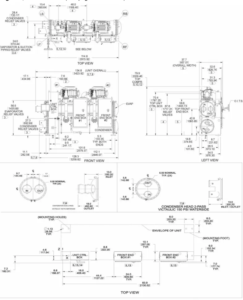
WMC 145S, Single Compressor
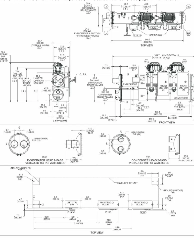
WMC 145D, 150D Dual Compressors
A circuit breaker is provided in each circuit after the power block or molded case disconnect switch.
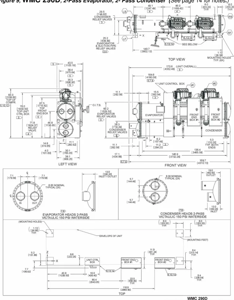
WMC250D and 290D Dual Compressor
Total Unit – 2 Compressors per Unit (RLA Per Compressor). Table 11, Single Point and Multipoint Connection. Multi-Point Connection Single-Point Connection RLA. Per Compressor) Disconnect Switch only Power Block Disconnect Switch. Optional customer supplied 115 VAC, 25-VA maximum coil rated, chilled water pump relays (ep1 & 2) can be wired as shown. A customer supplied 115 VAC 25 VA maximum coil rated, condenser water pump relays (CP1 & 2) must be wired as shown.
Use with On-Site Generators
An external 4-20mA chilled water reset signal is connected to terminals 71 and 51 on the unit controller; the load limit is connected to terminals 71 and 58 on the unit controller. An external 4-20mA chilled water reset signal is connected to terminals 71 and 51 on the unit controller; the load limit is connected to terminals 71 and 58 on the unit controller. The actual setting can be viewed on the user interface panel on the Setpoint/Timer screen.
System Pumps
A start signal can be given at any time after the stop signal, as the three-minute start-to-start timer will be in effect. Chiller Control Power: For proper operation on standby power, the chiller control power must remain as factory wired from a unit mounted transformer. Do not supply chiller control power from an external power source because the chiller may not sense a power loss and perform a normal shutdown sequence.
VFD Line Harmonics
Increase the capacity (lower the impedance) of the bus or cables from the source to the PCC. The harmonic filter is an option for field mounting and wiring outside the power panel. EMI is actually any frequency of electrical noise, while RFI is a specific subset of electrical noise in the EMI spectrum.
Multiple Chiller Setup
Chiller A
Chiller B
Operator Interface Touch Screen (OITS) Settings
For parallel operation with multiple chillers, the MicroTech II controllers are connected to a communications network and step and control compressor load between chillers. For example, if all are set to "1", auto lead/lag will apply. If any chiller is in a twin compressor group, it will be staged and loaded according to the setup instructions.
Prestart System Checklist
When the Delta-T above the set point reaches the Step Delta-T, the next chiller to start will receive a start signal and start its pumps if they are set to be controlled by the MicroTech II® controller.
Operation
Operator Responsibilities
Compressor Operation
Operating Limits
It is important to have adequate water volume in the system to provide an opportunity for the chiller to sense a change in load, adjust to the change, and stabilize. System water volume is the total amount of water in the evaporator, air handling products and associated piping. For process applications where the cooling load can change rapidly, additional system water volume is needed.
Control
If the water volume is too low, operational problems can occur, including rapid compressor changeovers, rapid loading and unloading of compressors, erratic chiller refrigerant flow, improper motor cooling, shortened equipment life, and other undesirable consequences. Some things the designer should consider when considering water volume are the minimum cooling load, the minimum capacity of the chiller during the low load period, and the desired cycle time for the compressors. Assuming there are no sudden load changes and that the chiller has reasonable outages, a rule of thumb of "gallons of water volume equals two to three times the chilled water gpm flow rate" is often used.
Building Automation Systems
BACnet/IP Ethernet 10 Base-T 10 Megabits/sec Color Graphics SBC Reference ED 15057: BACnet PICS BACnet MSTP RS485 (TBD) pCO2 Unit Controller Reference ED 15057: BACnet PICS. NOTE: For additional information on the protocol data available through the BACnet or LonTalk communication modules, refer to McQuay ED 15062, MicroTech II Chiller Unit Controller Protocol Information. Modbus - When selected, the identity number and baud can also be changed to suit the application.
Capacity Control System
Surge and Stall
Normal Unit Startup/Shutdown
Remote SWITCH Selecting SWITCH in SP3 will place the unit under control of a remote switch that must be wired to the controller. BAS Input The BAS is field connected to a communication module that is factory installed in the unit controller. A fourth switch located on the outer left of the unit's control panel and labeled EMERGENCY STOP stops the compressor immediately.
Annual Unit Startup/Shutdown
When these buttons are pressed, the unit will cycle through its normal start or stop sequence, both compressors will be stopped, and normal dual compressor start procedure will be in effect. COMPRESSOR a switch for each compressor on the unit, performs an immediate shutdown without the normal shutdown cycle.
Maintenance
Pressure/Temperature Chart
Routine Maintenance
Pump interlocks and flow switches should be checked to make sure they interrupt the control circuit when turned off. Permanent or cleanable filters in the air handling equipment must be cleaned in accordance with the manufacturer's instructions; disposable filters must be replaced. It must be recognized that atmospheric air contains many contaminants that increase the need for proper water treatment.
Repair of System
In this case, the unit should be leak tested to determine the location of the leak. In case of loss of the entire refrigerant charge, the unit must be checked for leaks before charging the entire system. This can be done by charging enough refrigerant into the system to build the pressure to about 10 psig (69 kPa) and adding enough dry nitrogen to bring the pressure to a maximum of 125 psig (860 kPa). Leak test with an electronic leak detector. Halide leak detectors do not function with R-134a. Water flow through the containers must be maintained any time coolant is added to or removed from the system. Do not use oxygen or a mixture of a refrigerant and air to build up pressure, as an explosion may occur, causing serious personal injury. If any leaks are found in welded or soldered joints, or it is necessary to replace a gasket, relieve the test pressure in the system before proceeding. Solder is required for copper joints. After any necessary repairs have been made, the system must be evacuated as described in the next section. After determining that there are no refrigerant leaks, the system should be evacuated using a vacuum pump with a capacity that will reduce the vacuum to at least 1000 microns of mercury. A mercury manometer or an electronic or other type of micron gauge must be connected to the far end of the vacuum pump. For readings below 1000 microns, an electronic or other micron gauge should be used. The triple evacuation method is recommended and is particularly useful if the vacuum pump cannot achieve the desired 1 millimeter vacuum. The system is only evacuated after about 29 inches of mercury. Dry nitrogen is then added to the system to bring the pressure to zero pounds. Then the system is evacuated again to about 29 inches of mercury. This is repeated three times. The first subtraction will remove about 90% of the non-condensables, the second about 90% of what remains from the first subtraction and, after the third, only 1/10-1% non-condensables will remain. McQuay water coolers are leak tested at the factory and shipped with the correct charge of coolant as indicated on the unit's nameplate. In the event that the refrigerant charge has been lost due to shipping damage, the system should be charged as follows after the leaks have been repaired and the system evacuated. Connect the coolant drum to the gauge port on the liquid line shut-off valve and clean the fill line between the coolant cylinder and the valve. Then open the valve to the middle position. Turn on both the cooling tower water pump and chilled water pump and circulate water through the condenser and the chiller. It may be necessary to manually close the condenser pump starter.). If the system is under a vacuum, stand up the refrigerant drum with the connector, and open the drum and break the vacuum with refrigerant gas to a saturated pressure above freezing. With a system gas pressure higher than the equivalent of a freezing temperature, the charging cylinder reverses and elevates the drum above the condenser. With the drum in this position, valves open, water. pumps are operating, liquid refrigerant will flow into the condenser. About 75% of the total requirement estimated for the unit can be charged in this way. After 75% of the required charge has entered the condenser, reconnect the refrigerant drum and charge line to the service valve at the bottom of the evaporator. Clean the connection line again, stand up the drum with the connection and place the service valve in the open position. IMPORTANT: At this point, the charging procedure must be interrupted and pre-start checks performed before attempting to complete the cooling. compressor should not be switched on at this time. Preliminary check must be completed first.).
Maintenance Schedule
Service Programs
Operator Schools
Limited Warranty