TECHNICAL & SERVICE MANUAL
utilized
R410A
CONTENTS
1. SAFETY PRECAUTION ...2
2. OVERVIEW OF UNITS ...5
3. SPECIFICATIONS ...9
4. DATA ...10
5. OUTLINES AND DIMENSIONS ...18
6. WIRING DIAGRAM ...19
Note:• This service manual describes technical data of the outdoor units only.
No. OCH675
REVISED EDITION-D SPLIT-TYPE, HEAT PUMP AIR CONDITIONERS
June 2019
OCH675 REVISED EDITION-C is void.
Revision:
• PUMY-P200YKM2R1 and PUMY-P200YKM2R1-BS have neen added.
• Some descriptions have been modified in REVISED EDITION-D.
<Outdoor unit>
[Model Name]
PUMY-P200YKM2
PUMY-P200YKM2 PUMY-P200YKM2R1 PUMY-P200YKM2-BS PUMY-P200YKM2R1-BS
[Service Ref.]
Salt proof model
PUMY-P200YKM2-BS
Cautions for units utilizing refrigerant R410A
1-1. CAUTIONS RELATED TO NEW REFRIGERANT
1 SAFETY PRECAUTION
Use new refrigerant pipes.
Avoid using thin pipes.
Use a vacuum pump with a reverse flow check valve.
Vacuum pump oil may flow back into refrigerant cycle and that can cause deterioration of refrigerant oil, etc.
Handle tools with care.
If dirt, dust or moisture enters into refrigerant cycle, that can cause deterioration of refrigerant oil or malfunction of compressor.
Do not use a charging cylinder.
If a charging cylinder is used, the composition of refrigera- nt will change and the efficiency will be lowered.
Use the specified refrigerant only.
Never use any refrigerant other than that specified.
Doing so may cause a burst, an explosion, or fire when the unit is being used, serviced, or disposed of.
Correct refrigerant is specified in the manuals and on the spec labels provided with our products.
We will not be held responsible for mechanical failure, system malfunction, unit breakdown or accidents caused by failure to follow the instructions.
Ventilate the room if refrigerant leaks during operation. If refrigerant comes into contact with a flame, poisonous gases will be released.
Use the following tools specifically designed for use with R410A refrigerant.
The following tools are necessary to use R410A refrigerant.
Tools for R410A Gauge manifold Flare tool
Charge hose Size adjustment gauge
Gas leak detector Vacuum pump adaptor Torque wrench Electronic refrigerant
charging scale
Make sure that the inside and outside of
refrigerant piping is clean and it has no contaminants such as sulfur, oxides, dirt, shaving particles, etc., which are hazard to refrigerant cycle.
In addition, use pipes with specified thickness.
Contamination inside refrigerant piping can cause deterio- ration of refrigerant oil, etc.
Store the piping indoors, and keep both ends of the piping sealed until just before brazing.
(Leave elbow joints, etc. in their packaging.)
If dirt, dust or moisture enters into refrigerant cycle, that can cause deterioration of refrigerant oil or malfunction of compressor.The refrigerant oil applied to flare and flange connections must be ester oil, ether oil or alkylbenzene oil in a small amount.
If large amount of mineral oil enters, that can cause deterioration of refrigerant oil, etc.
Charge refrigerant from liquid phase of gas cylinder.
If the refrigerant is charged from gas phase, composition change may occur in refrigerant and the efficiency will be lowered.
Do not use refrigerant other than R410A.
If other refrigerant (R22, etc.) is used, chlorine in refrigerant can cause deterioration of refrigerant oil, etc.
Precautions during the repair service
• Do not perform the work involving the electric parts with wet hands.
• Do not pour water into the electric parts.
• Do not touch the refrigerant.
• Do not touch the hot or cold areas in the refrigerating cycle.
• When the repair or the inspection of the circuit needs to be done without turning off the power, exercise great caution not to touch the live parts.
Preparation before the repair service
• Prepare the proper tools.
• Prepare the proper protectors.
• Provide adequate ventilation.
• After stopping the operation of the air conditioner, turn off the power-supply breaker.
• Discharge the condenser before the work involving the electric parts.
Electronic weighing scale
Unit
[3] Service tools
Use the below service tools as exclusive tools for R410A refrigerant.
(1) Perform service after recovering the refrigerant left in unit completely.
(2) Do not release refrigerant in the air.
(3) After completing service, charge the cycle with specified amount of refrigerant.
(4) If moisture or foreign matter might have entered the refrigerant piping during service, ensure to remove them.
[2] Additional refrigerant charge
When charging directly from cylinder
(1) Check that cylinder for R410A on the market is a syphon type.
(2) Charging should be performed with the cylinder of syphon stood vertically. (Refrigerant is charged from liquid phase.)
1-2. PRECAUTIONS FOR SALT PROOF TYPE "-BS" MODEL
No. Tool name Specifications
1 Gauge manifold · Only for R410A
· Use the existing fitting specifications. (UNF1/2)
· Use high-tension side pressure of 5.3MPa·G or over.
2 Charge hose · Only for R410A
· Use pressure performance of 5.09MPa·G or over.
3 Electronic weighing scale —
4 Gas leak detector · Use the detector for R134a, R407C or R410A.
5 Adaptor for reverse flow check · Attach on vacuum pump.
6 Refrigerant charge base —
7 Refrigerant cylinder · Only for R410A · Top of cylinder (Pink)
· Cylinder with syphon
8 Refrigerant recovery equipment —
Cautions for refrigerant piping work
New refrigerant R410A is adopted for replacement inverter series. Although the refrigerant piping work for R410A is same as for R22, exclusive tools are necessary so as not to mix with different kind of refrigerant. Furthermore as the working pressure of R410A is 1.6 times higher than that of R22, their sizes of flared sections and flare nuts are different.
1 Thickness of pipes
Because the working pressure of R410A is higher compared to R22, be sure to use refrigerant piping with thickness shown below. (Never use pipes of 0.7 mm or below.)
Diagram below: Piping diameter and thickness Nominal
dimensions (in)
Outside diameter (mm)
Thickness (mm)
R410A R22
1/4 6.35 0.8 0.8
3/8 9.52 0.8 0.8
1/2 12.70 0.8 0.8
5/8 15.88 1.0 1.0
3/4 19.05 1.0* 1.0
7/8 22.2 1.0* 1.0
* Use 1/2 H or H pipes.
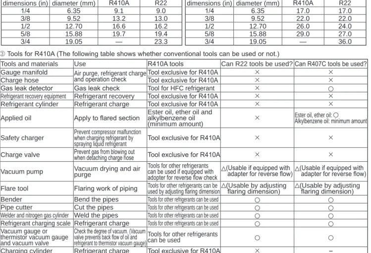
2 Dimensions of flare cutting and flare nut
The component molecules in HFC refrigerant are smaller compared to conventional refrigerants. In addition to that, R410A is a refrigerant, which has higher risk of leakage because its working pressure is higher than that of other refrig- erants. Therefore, to enhance airtightness and strength, flare cutting dimension of copper pipe for R410A has been specified separately from the dimensions for other refrigerants as shown below. The dimension B of flare nut for R410A also has partly been changed to increase strength as shown below. Set copper pipe correctly referring to copper pipe flaring dimensions for R410A below. For 1/2 and 5/8 inch pipes, the dimension B changes.
Use torque wrench corresponding to each dimension.
Dimension A
Dimension B
Flare cutting dimensions Nominal
dimensions (in)
Outside diameter (mm)
Dimension A ( )(mm)
R410A R22
1/4 6.35 9.1 9.0
3/8 9.52 13.2 13.0
1/2 12.70 16.6 16.2
5/8 15.88 19.7 19.4
3/4 19.05 — 23.3
+0-0.4
Flare nut dimensions Nominal
dimensions (in)
Outside diameter (mm)
Dimension B(mm)
R410A R22
1/4 6.35 17.0 17.0
3/8 9.52 22.0 22.0
1/2 12.70 26.0 24.0
5/8 15.88 29.0 27.0
3/4 19.05 — 36.0
3 Tools for R410A (The following table shows whether conventional tools can be used or not.)
Tools and materials Use R410A tools Can R22 tools be used?Can R407C tools be used?
Gauge manifold Air purge, refrigerant charge
and operation check Tool exclusive for R410A
Charge hose Tool exclusive for R410A
Gas leak detector Gas leak check Tool for HFC refrigerant Refrigerant recovery equipment Refrigerant recovery Tool exclusive for R410A Refrigerant cylinder Refrigerant charge Tool exclusive for R410A Applied oil Apply to flared section Ester oil, ether oil and
alkylbenzene oil (minimum amount)
Ester oil, ether oil:
Alkylbenzene oil: minimum amount Safety charger Prevent compressor malfunction
when charging refrigerant by
spraying liquid refrigerant Tool exclusive for R410A Charge valve Prevent gas from blowing out
when detaching charge hose Tool exclusive for R410A Vacuum pump Vacuum drying and air
purge
Tools for other refrigerants can be used if equipped with adopter for reverse flow check
(Usable if equipped with
adapter for reverse flow) (Usable if equipped with adapter for reverse flow) Flare tool Flaring work of piping Tools for other refrigerants can be
used by adjusting flaring dimension (Usable by adjusting
flaring dimension) (Usable by adjusting flaring dimension) Bender Bend the pipes Tools for other refrigerants can be used
Pipe cutter Cut the pipes Tools for other refrigerants can be used Welder and nitrogen gas cylinder Weld the pipes Tools for other refrigerants can be used Refrigerant charging scale Refrigerant charge Tools for other refrigerants can be used Vacuum gauge or
thermistor vacuum gauge and vacuum valve
Check the degree of vacuum. (Vacuum valve prevents back flow of oil and refrigerant to thermistor vacuum gauge)
Tools for other refrigerants can be used
Charging cylinder Refrigerant charge Tool exclusive for R410A ─
: Prepare a new tool. (Use the new tool as the tool exclusive for R410A.)
2
2-1. SYSTEM CONSTRUCTION
OVERVIEW OF UNITS
Model
Capacity
Cassette Ceiling Ceiling
Concealed Wall Mounted Ceiling
Suspended Floor standing Ceiling concealed Lossnay
CONNECTION KIT
2 by 2 4-way flow 2-way flow 1-way flow Exposed Concealed Fresh air*1 PAC-LV11M-J
PLFY-P PLFY-P PLFY-EP*6 PLFY-P PMFY-P PEFY-P PKFY-P PCFY-P PFFY-P PFFY-P PEFY-P GUF*5
10 – – – – – – 10VLM-E – – – – –
15 15VFM-E1
15VCM-E – – – – 15VMS1(L)-E 15VBM-E15VLM-E – – – – –
20 20VFM-E1 20VCM-E 20VBM-E
20VEM-E – 20VLMD-E 20VBM-E
20VMS1(L)-E 20VMA(L)-E 20VMA(L)-E3 20VMR-E-L/R
20VBM-E
20VLM-E – 20VLEM-E 20VKM-E2
20VLRM-E
20VLRMM-E – –
25 25VFM-E1 25VCM-E 25VBM-E
25VEM-E – 25VLMD-E 25VBM-E
25VMS1(L)-E 25VMA(L)-E 25VMA(L)-E3 25VMR-E-L/R
25VBM-E
25VLM-E – 25VLEM-E 25VKM-E2
25VLRM-E
25VLRMM-E – –
32 32VFM-E1 32VCM-E 32VBM-E
32VEM-E – 32VLMD-E 32VBM-E
32VMS1(L)-E 32VMA(L)-E 32VMA(L)-E3 32VMR-E-L/R
32VHM-E
32VLM-E – 32VLEM-E 32VKM-E2
32VLRM-E
32VLRMM-E – –
40 40VFM-E1 40VCM-E 40VBM-E
40VEM-E – 40VLMD-E 40VBM-E
40VMS1(L)-E 40VMA(L)-E 40VMA(L)-E3 40VMA3-E*4 40VMH-E
40VHM-E
40VLM-E 40VKM-E 40VLEM-E
40VKM-E2 40VLRM-E
40VLRMM-E – –
M series indoor unit *3 MSZ-GE series MSZ-EF Series MSZ-SF Series MSZ-FH Series MFZ-KJ Series MSZ-LN·VG Series MSZ-AP·VG Series MSZ-AP·VF Series 50 50VFM-E1 50VBM-E
50VEM-E – 50VLMD-E –
50VMS1(L)-E 50VMA(L)-E 50VMA(L)-E3 50VMH-E
50VHM-E
50VLM-E – 50VLEM-E 50VLRM-E
50VLRMM-E – 50RD(H)4
63 – 63VBM-E
63VEM-E 63VEM-E 63VLMD-E –
63VMS1(L)-E 63VMA(L)-E 63VMA(L)-E3 63VMA3-E*4 63VMH-E
63VKM-E 63VKM-E 63VLEM-E 63VLRM-E
63VLRMM-E – –
71 – – – – –
71VMA(L)-E 71VMA(L)-E3
71VMH-E – – – – – –
80 – 80VBM-E
80VEM-E – 80VLMD-E –
80VMA(L)-E 80VMA(L)-E3
80VMH-E – – – – – –
100 – 100VBM-E
100VEM-E – 100VLMD-E –
100VMA(L)-E 100VMA(L)-E 100VMA(L)-E3
100VMH-E
100VKM-E 100VKM-E – – – 100RD(H)4
125 – 125VBM-E
125VEM-E – 125VLMD-E –
125VMA(L)-E 125VMA(L)-E3
125VMH-E – 125VKM-E – – – –
140 – – – – – 140VMA(L)-E
140VMA(L)-E3
140VMH-E – – – – – –
200 – – – – – 200VMHS-E
200VMH-E – – – – 200VMH-E-F –
Note: Only for R1 models: PEFY-P·VMA(L)-E3, PKFY-P·VLM-E
Outdoor unit
8HP PUMY-P200YKM2(R1) PUMY-P200YKM2(R1)-BS Applicable
indoor unit
Capacity Type 10 to Type 200
Number of units 1 to 12 unit
Total system capacity range 50 to 130% of outdoor unit capacity *2
CMY-Y62-G-E CMY-Y64-G-E CMY-Y68-G-E
Branching pipe components
Branch header (2 branches)
Branch header
(4 branches) Branch header
(8 branches)
2-2. SYSTEM CONSTRUCTION (BRANCH BOX SYSTEM)
Model
[kW type]
Capacity
Wall Mounted Floor
standing
1-way ceiling cassette
Ceiling concealed
Ceiling suspended
4-way ceiling cassette Low static
pressure
Middle static pressure
2 by 2 type Standard MSZ-FH MSZ-LN MSZ-EF MSZ-GF MSZ-SF MSZ-AP MFZ-KJ MLZ-KA MLZ-KP SEZ-KD SEZ-M PEAD-RP PEAD-MPCA-RP
PCA-M SLZ-KF
SLZ-M PLA-RP
PLA-M
15 ─ ─ ─ ─ 15VA 15VF
15VG ─ ─ ─ ─ ─ ─ ─ ─ 15FA ─
18 ─ ─ 18VE
18VG ─ ─ ─ ─ ─ ─ ─ ─ ─ ─ ─ ─ ─
20 ─ ─ ─ ─ 20VA 20VF
20VG ─ ─ ─ ─ ─ ─ ─ ─ ─ ─
22 ─ ─ 22VE
22VG ─ ─ ─ ─ ─ ─ ─ ─ ─ ─ ─ ─ ─
25 25VE 25VG 25VE
25VG ─ 25VE 25VG 25VE2 25VA 25VF 25VA(L) 25DA(L) ─ ─ ─ 25VA2
25FA ─
35 35VE 35VG 35VE
35VG ─ 35VE 35VG 35VE2 35VA 35VF 35VA(L) 35DA(L) ─ ─ 35KAQ
35KA 35VA2
35FA 35EA
42 ─ ─ 42VE
42VG ─ 42VE 42VG ─ ─ ─ ─ ─ ─ ─ ─ ─ ─
50 50VE 50VG 50VE
50VG ─ 50VE 50VG 50VE2 50VA 50VF 50VA(L) 50DA(L) 50JA(L)Q 50JA(L) 50KAQ 50KA
50VA2 50FA 50EA
60 ─ ─ ─ 60VE ─ ─ ─ ─ ─ 60VA(L) 60DA(L) 60JA(L)Q 60JA(L) 60KAQ
60KA ─ 60EA
71 ─ ─ ─ 71VE ─ ─ ─ ─ ─ 71VA(L) 71DA(L) 71JA(L)Q 71JA(L) 71KAQ
71KA ─ 71EA
100 ─ ─ ─ ─ ─ ─ ─ ─ ─ ─ ─ 100JA(L)Q 100JA(L) 100KAQ
100KA ─ 100EA
Note1: The lineup of a connectable indoor unit depends on a district/areas/country.
Note2: Only for R1 models: MSZ-EF·VG, MSZ-AP·VG, PLA-M·EA Outdoor unit
8HP
PUMY-P200YKM2(R1) PUMY-P200YKM2(R1)-BS Applicable indoor unit
Capacity kW unit: Type 15 to Type 100
Number of units 2 to 8 units
Total system capacity range 50 to 130 % of outdoor unit capacity (11.2 to 29.1 kW) Branch box that can be
connected Number of units 1 to 2 units*
* The maximum total capacity of the units that can be connected to each branch box is 20.2 kW.
Branch box PAC-MK51/53BC(B) PAC-MK31/33BC(B) Note: A maximum of 2 branch boxes can be connected to 1 outdoor unit.
Number of branches Indoor unit that can be connected
5 branches (MAX. 5 units)
3 branches (MAX. 3 units)
Option Optional accessories of indoor units and outdoor units are available.
2- branch pipe (joint): Optional parts
In case of using 1- branch box No need
In case of using 2- branch boxes
Model name Connection method
MSDD-50AR-E flare
MSDD-50BR-E brazing
Select a model according to the connection method.
Outdoor unit
8HP
PUMY-P200YKM2(R1) PUMY-P200YKM2(R1)-BS Applicable
indoor unit
Capacity CITY MULTI indoor unit Type 10 to Type 200
Via branch box kW unit: Type 15 to Type 100
Number of units
Via branch box CITY MULTI indoor
1-branch box *1 5 5
2-branch box *1 8 3
Total system capacity range 11.2 to 29.1 kW
50 to 130% of outdoor unit capacity
*1 The maximum total capacity of the units that can be connected to each branch box is 20.2 kW.
Branching pipe components
CMY-Y62-G-E CMY-Y64-G-E CMY-Y68-G-E Branch box Number of
branches
PAC-MK51/53BC(B) PAC-MK31/33BC(B) Branch header
(2 branches)
Branch header
(4 branches) Branch header (8 branches)
5 branches (MAX. 5 units)
3 branches (MAX. 3 units)
CITY MULTI indoor units *2
M series S series P series indoor units *2
MA remote controller
MA remote controller
M series remote controller CONNECTION KIT
PAC-LV11M-J
M series indoor unit
M series remote controller
*2 Refer to “2-1. SYSTEM CONSTRUCTION” and/or “2-2. SYSTEM CONSTRUCTION (BRANCH BOX SYSTEM) for more detail.
2-4. SYSTEM SPECIFICATIONS
(2) Method for identifying MULTI-S model (1) Outdoor Unit
Outdoor unit <When using model 200 >
Service Ref. PUMY-P200YKM2(R1)
PUMY-P200YKM2(R1)-BS
Capacity Cooling (kW) 22.4
Heating (kW) 25.0
Compressor (kW) 5.3
Cooling/Heating capacity indicates the maximum value at operation under the following condition.
Cooling Indoor : D.B. 27°C/W.B. 19.0°C
Outdoor: D.B. 35°C
Heating Indoor : D.B. 20°C Outdoor: D.B. 7°C/W.B. 6°C
PU M Y ─ P 200 Y K M 2 ─ BS
Outdoor unit Refrigerant R410A MULTI-S
Frequency conversion controller Indicates equivalent to Cooling capacity(kcal/ h)
Power supply Y: 3-phase
380-400-415 V, 50/60 Hz Outdoor unit model type
M-NET control Sub-
number
Salt proof type
(3) Operating temperature range
Cooling Heating
Indoor-side intake air temperature W.B. 15 to 24°C D.B. 15 to 27°C Outdoor-side intake air temperature D.B. −5 to 52°C* W.B. −20 to 15°C Notes: D.B.: Dry Bulb Temperature
W.B.: Wet Bulb Temperature
* 10 to 52°C D.B.: When connecting PKFY-P15/20/25VBM, PKFY-P10/15/20/25/32VLM, PFFY-P20/25/32VKM, PFFY-P20/25/32VLE(R)M, PEFY-P40/63VMA3-E; and M series, S series, and P series type indoor unit.
■ When connecting fresh air type indoor unit
. (Only P200)• PEFY-P·VHM-E-F
Cooling Heating
Indoor-side and Outdoor-side intake air temperature D.B. 21 to 43ºC*
W.B. 15.5 to 35ºC D.B. −10 to 20ºC**
*Thermo-OFF (FAN-mode) automatically starts if the outdoor temperature is lower than 21ºC D.B.
**Thermo-OFF (FAN-mode) automatically starts if the outdoor temperature is higher than 20ºC D.B.
3 SPECIFICATIONS
Service Ref. PUMY-P200YKM2(R1), PUMY-P200YKM2(R1)-BS
Power source 3-phase 380-400-415 V, 50 Hz
Cooling capacity (Nominal)
kW *1 22.4
kcal/h *1 19,300
Btu/h *1 76,400
Power input kW 6.05
Current input A 9.88- 9.39- 9.05
EER kW/kW 3.70
Temp. range of cooling
Indoor temp. W.B. 15 to 24°C
Outdoor temp. D.B. −5 to 52°C *3,*4
Heating capacity (Nominal)
kW *2 25.0
kcal/h *2 21,500
Btu/h *2 85,300
Power input kW 5.84
Current input A 9.54- 9.06- 8.74
COP kW/kW 4.28
Temp. range of heating
Indoor temp. D.B. 15 to 27°C
Outdoor temp. W.B. −20 to 15°C *3,*4
Indoor unit connectable
Total capacity 50 to 130% of outdoor unit capacity
Model/Quantity
CITY MULTI P10–P200/12
Branch box kW type: P15–P100/8
Mixed system
Branch box 1 unit
CITY MULTI P10–P200/5
Branch box kW type: P15–P100/5
Branch box 2 units
CITY MULTI P10–P200/3
Branch box kW type: P15–P100/8
Sound pressure level (SPL) (measured in anechoic room) dB <A> 56/61 Power pressure level (PWL) (measured in anechoic room)dB <A> 75/80 Refrigerant
piping diameter
Liquid pipe mm (inch) 9.52 (3/8)*5
Gas pipe mm (inch) 19.05 (3/4)
FAN Type × Quantity Propeller Fan × 2
Airflow rate m³/min 139/141
L/s 2,317/2,350
cfm 4,909/4,979
Control, Driving mechanism DC control
Motor output kW 0.20 + 0.20
External static pressure 0
Compressor Type × Quantity Scroll hermetic compressor × 1
Manufacturer Siam Compressor Industry Co., Ltd.
Starting method Inverter
Capacity control % Cooling 25 to100
Heating 17 to 100
Motor output kW 5.3
Case heater kW 0
Lubricant FVC68D (2.3litter)
External finish Galvanized Steel Sheet
Munsell No. 3Y 7.8/1.1
External dimension HxWxD mm 1,338×1,050×330(+40)
inch 52-11/16 × 41-11/32 × 13(+1-10/16)
Protection devices High pressure protection High pressure Switch
Inverter circuit (COMP./FAN) Overcurrent detection, Overheat detection(Heat sink thermistor)
Compressor Compressor thermistor, Over current detection
Fan motor Overheating, Voltage protection
Refrigerant Type × original charge R410A 7.3 kg
Control Linear Expansion Valve
Net weight kg (lb) 141 (311)
Heat exchanger Cross Fin and Copper tube
HIC circuit (HIC: Heat Inter-Changer) HIC circuit
Defrosting method Reversed refrigerant circuit
4-1. SELECTION OF COOLING/HEATING UNITS
4 DATA
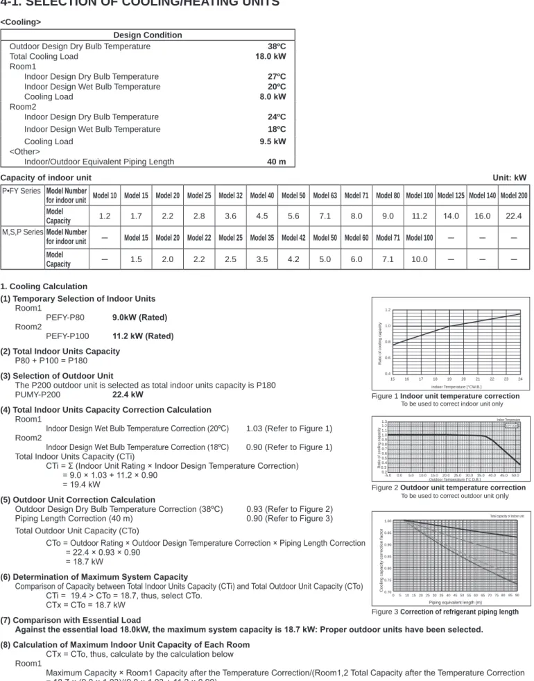
<Cooling>
Design Condition
Outdoor Design Dry Bulb Temperature 38ºC
Total Cooling Load 18.0 kW
Room1
Indoor Design Dry Bulb Temperature 27ºC
Indoor Design Wet Bulb Temperature 20ºC
Cooling Load 8.0 kW
Room2
Indoor Design Dry Bulb Temperature 24ºC
Indoor Design Wet Bulb Temperature 18ºC
Cooling Load 9.5 kW
<Other>
Indoor/Outdoor Equivalent Piping Length 40 m
Capacity of indoor unit Unit: kW
P•FY Series Model Number
for indoor unit Model 10 Model 15 Model 20 Model 25 Model 32 Model 40 Model 50 Model 63 Model 71 Model 80 Model 100 Model 125 Model 140 Model 200 Model
Capacity 1.2 1.7 2.2 2.8 3.6 4.5 5.6 7.1 8.0 9.0 11.2 14.0 16.0 22.4
M,S,P SeriesModel Number
for indoor unit ─ Model 15 Model 20 Model 22 Model 25 Model 35 Model 42 Model 50 Model 60 Model 71 Model 100 ─ ─ ─ Model
Capacity ─ 1.5 2.0 2.2 2.5 3.5 4.2 5.0 6.0 7.1 10.0 ─ ─ ─
1. Cooling Calculation
(1) Temporary Selection of Indoor Units Room1
PEFY-P80 9.0kW (Rated)
Room2
PEFY-P100 11.2 kW (Rated)
(2) Total Indoor Units Capacity P80 + P100 = P180 (3) Selection of Outdoor Unit
The P200 outdoor unit is selected as total indoor units capacity is P180
PUMY-P200 22.4 kW
(4) Total Indoor Units Capacity Correction Calculation Room1
Indoor Design Wet Bulb Temperature Correction (20ºC) 1.03 (Refer to Figure 1) Room2
Indoor Design Wet Bulb Temperature Correction (18ºC) 0.90 (Refer to Figure 1) Total Indoor Units Capacity (CTi)
CTi = Σ (Indoor Unit Rating × Indoor Design Temperature Correction)
= 9.0 × 1.03 + 11.2 × 0.90
= 19.4 kW
(5) Outdoor Unit Correction Calculation
Outdoor Design Dry Bulb Temperature Correction (38ºC) 0.93 (Refer to Figure 2) Piping Length Correction (40 m) 0.90 (Refer to Figure 3) Total Outdoor Unit Capacity (CTo)
CTo = Outdoor Rating × Outdoor Design Temperature Correction × Piping Length Correction
= 22.4 × 0.93 × 0.90
= 18.7 kW
(6) Determination of Maximum System Capacity
Comparison of Capacity between Total Indoor Units Capacity (CTi) and Total Outdoor Unit Capacity (CTo) CTi = 19.4 > CTo = 18.7, thus, select CTo.
CTx = CTo = 18.7 kW (7) Comparison with Essential Load
Against the essential load 18.0kW, the maximum system capacity is 18.7 kW: Proper outdoor units have been selected.
(8) Calculation of Maximum Indoor Unit Capacity of Each Room CTx = CTo, thus, calculate by the calculation below Room1
Maximum Capacity × Room1 Capacity after the Temperature Correction/(Room1,2 Total Capacity after the Temperature Correction
= 18.7 × (9.0 × 1.03)/(9.0 × 1.03 + 11.2 × 0.90)
= 9.0 kW OK: fulfills the load 8.0 kW Room2
Maximum Capacity × Room2 Capacity after the Temperature Correction/(Room1,2 Total Capacity after the Temperature Correction)
= 18.7 × (11.20 × 0.90)/(9.0 × 1.03 + 11.2 × 0.90)
= 9.7 kW OK: fulfills the load 9.5 kW
Note: If CTx = CTi, please refer to the <Heating> section to calculate the Maximum Indoor Unit Capacity of Each Room.
Indoor Temperature [°CW.B.]
Ratio of cooling capacity
15 16 17 18 19 20 21 22 23 24
0.4 0.6 0.8 1.0 1.2
Ratio of cooling capacity
Outdoor Temperature [°C D.B.]
-5.0 0.0 5.0 10.015.0 20.0 25.0 30.0 35.040.0 45.050.0 0.2
0.3 0.4 0.5 0.6 0.7 0.8 0.9 1.0 1.1 1.2
1.3 Indoor Temperature
19°C W.B
Total capacity of indoor unit
Cooling capacity correction factor
Piping equivalent length (m)
0 510 15 20 25 30 35 40 45 50 55 60 65 70 75 8085 90 0.70
0.75 0.80 0.85 0.90 0.95 1.00
Figure 1 Indoor unit temperature correction To be used to correct indoor unit only
Figure 2 Outdoor unit temperature correction To be used to correct outdoor unit only
Figure 3 Correction of refrigerant piping length
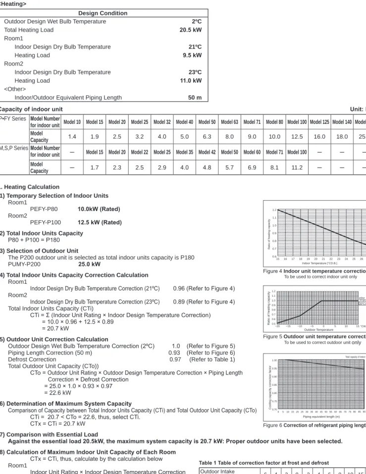
Design Condition
Outdoor Design Wet Bulb Temperature 2ºC
Total Heating Load 20.5 kW
Room1
Indoor Design Dry Bulb Temperature 21ºC
Heating Load 9.5 kW
Room2
Indoor Design Dry Bulb Temperature 23ºC
Heating Load 11.0 kW
<Other>
Indoor/Outdoor Equivalent Piping Length 50 m
Capacity of indoor unit Unit: kW
P•FY Series Model Number
for indoor unit Model 10 Model 15 Model 20 Model 25 Model 32 Model 40 Model 50 Model 63 Model 71 Model 80 Model 100 Model 125 Model 140 Model 200 Model
Capacity 1.4 1.9 2.5 3.2 4.0 5.0 6.3 8.0 9.0 10.0 12.5 16.0 18.0 25.0
M,S,P SeriesModel Number
for indoor unit ─ Model 15 Model 20 Model 22 Model 25 Model 35 Model 42 Model 50 Model 60 Model 71 Model 100 ─ ─ ─ Model
Capacity ─ 1.7 2.3 2.5 2.9 4.0 4.8 5.7 6.9 8.1 11.2 ─ ─ ─
1. Heating Calculation
(1) Temporary Selection of Indoor Units Room1
PEFY-P80 10.0kW (Rated)
Room2
PEFY-P100 12.5 kW (Rated)
(2) Total Indoor Units Capacity P80 + P100 = P180 (3) Selection of Outdoor Unit
The P200 outdoor unit is selected as total indoor units capacity is P180
PUMY-P200 25.0 kW
(4) Total Indoor Units Capacity Correction Calculation Room1
Indoor Design Dry Bulb Temperature Correction (21ºC) 0.96 (Refer to Figure 4) Room2
Indoor Design Dry Bulb Temperature Correction (23ºC) 0.89 (Refer to Figure 4) Total Indoor Units Capacity (CTi)
CTi = Σ (Indoor Unit Rating × Indoor Design Temperature Correction)
= 10.0 × 0.96 + 12.5 × 0.89
= 20.7 kW
(5) Outdoor Unit Correction Calculation
Outdoor Design Wet Bulb Temperature Correction (2ºC) 1.0 (Refer to Figure 5) Piping Length Correction (50 m) 0.93 (Refer to Figure 6)
Defrost Correction 0.97 (Refer to Table 1)
Total Outdoor Unit Capacity (CTo))
CTo = Outdoor Unit Rating × Outdoor Design Temperature Correction × Piping Length Correction × Defrost Correction
= 25.0 × 1.0 × 0.93 × 0.97
= 22.6 kW
(6) Determination of Maximum System Capacity
Comparison of Capacity between Total Indoor Units Capacity (CTi) and Total Outdoor Unit Capacity (CTo)
15 16 17 18 19 20 21 22 23 24 25 26 27
0.6 0.7 0.8 0.9 1.0 1.1 1.2
Ratio of heating capacity
Indoor Temperature [°CD.B.]
Ratio of heating capacity °CW.B.
Indoor Temperature
Outdoor Temperature 0.5
0.6 0.7 0.8 0.9 1.0 1.1 1.2
−20 −15 −10 −5 0 5 10 15
20°C D.B.
Total capacity of indoor unit
0.75 0.80 0.85 0.90 0.95 1.00
Figure 4 Indoor unit temperature correction To be used to correct indoor unit only
Figure 5 Outdoor unit temperature correction To be used to correct outdoor unit only
4-2. CORRECTION BY TEMPERATURE
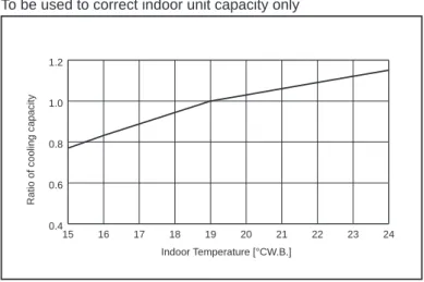
15 16 17 18 19 20 21 22 23 24
0.4 0.6 0.8 1.0 1.2
Ratio of cooling capacity
Indoor Temperature [°CW.B.]
Ratio of cooling capacity
Outdoor Temperature [°C D.B.]
Indoor Temperature
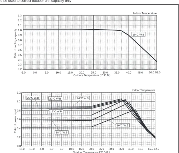
-5.0 0.0 5.0 10.0 15.0 20.0 25.0 30.0 35.0 40.0 45.0 50.0 52.0
0.2 0.3 0.4 0.5 0.6 0.7 0.8 0.9 1.0 1.1 1.2 1.3
19°C W.B
Ratio of power input
Outdoor Temperature [°C D.B.]
Indoor Temperature
-15.0 -10.0 -5.0 0.0 5.0 10.0 15.0 20.0 25.0 30.0 35.0 40.0 45.0 50.0 52.0 0.0
0.2 0.4 0.6 0.8 1.0 1.2
16°C W.B 18°C W.B
19°C W.B
20°C W.B 22°C W.B 24°C W.B
The outdoor units have varied capacity at different designing temperature. Using the nominal cooling/heating capacity value and the ratio below, the capacity can be observed at various temperature.
Figure 7 Indoor unit temperature correction To be used to correct indoor unit capacity only
Figure 8 Outdoor unit temperature correction To be used to correct outdoor unit capacity only
<Cooling>
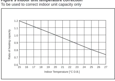
15 16 17 18 19 20 21 22 23 24 25 26 27 0.6
0.7 0.8 0.9 1.0 1.1 1.2
Ratio of heating capacity
Indoor Temperature [°C D.B.]
Ratio of heating capacity
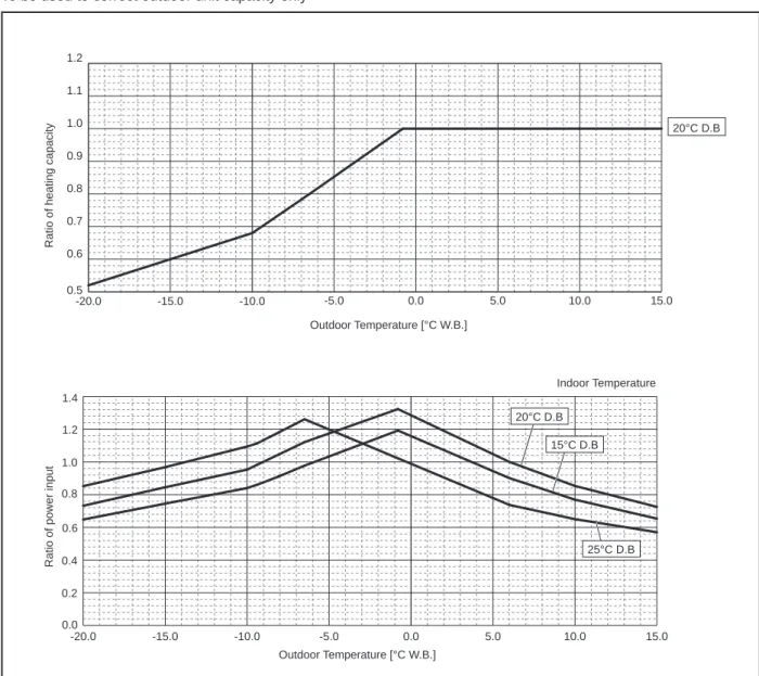
Outdoor Temperature [°C W.B.]
20°C D.B
-20.0 -15.0 -10.0 -5.0 0.0 5.0 10.0 15.0
0.5 0.6 0.7 0.8 0.9 1.0 1.1 1.2
Indoor Temperature
0.8 1.0 1.2 1.4
15°C D.B 20°C D.B
Figure 9 Indoor unit temperature correction To be used to correct indoor unit capacity only
Figure 10 Outdoor unit temperature correction To be used to correct outdoor unit capacity only
4-3. STANDARD CAPACITY DIAGRAM
Before calculating the sum of total capacity of indoor units, please convert the value into the kW model capacity following the formula on "4-1. SELECTION OF COOLING/HEATING UNITS".
4-3-1. PUMY-P200YKM2 PUMY-P200YKM2-BS <Cooling>
PUMY-P200YKM2R1 PUMY-P200YKM2R1-BS
0.0 5.0 10.0 15.0 20.0 25.0
2.0 4.0 6.0 8.0 10.0 12.0 14.0 16.0 18.0 20.0 22.0 24.0 26.0 28.0 30.0
2.0 4.0 6.0 8.0 10.0 12.0 14.0 16.0 18.0 20.0 22.0 24.0 26.0 28.0 30.0
2.0 4.0 6.0 8.0 10.0 12.0 14.0 16.0 18.0 20.0 22.0 24.0 26.0 28.0 30.0 0.0
1.0 2.0 3.0 4.0 5.0 6.0 7.0
0.0 2.0 4.0 6.0 8.0 10.0 12.0
380V 400V 415V
Capacity(kW)
Total capacity of indoor units(kW)
Total capacity of indoor units(kW)
Input(kW) Current(A)
Total capacity of indoor units(kW)
PUMY-P200YKM2R1 PUMY-P200YKM2R1-BS
2.0 4.0 6.0 8.0 10.0 12.0 14.0 16.0 18.0 20.0 22.0 24.0 26.0 28.0 30.0 2.0 4.0 6.0 8.0 10.0 12.0 14.0 16.0 18.0 20.0 22.0 24.0 26.0 28.0 30.0
0.0 1.0 2.0 3.0 4.0 5.0 6.0 7.0
6.0 8.0 10.0 12.0 0.0 5.0 10.0 15.0 20.0 25.0 30.0
Capacity(kW)
Total capacity of indoor units(kW)
Total capacity of indoor units(kW)
Input(kW)
4-4. CORRECTING CAPACITY FOR CHANGES IN THE LENGTH OF REFRIGERANT PIPING
(1) During cooling, obtain the ratio (and the equivalent piping length) of the outdoor units rated capacity and the total in-use indoor capacity, and find the capacity ratio corresponding to the standard piping length from Figure 11. Then multiply by the cooling capacity from Figure 7 and 8 in "4-2. CORRECTION BY TEMPERATURE" to obtain the actual capacity.
(2) During heating, find the equivalent piping length, and find the capacity ratio corresponding to standard piping length from Figure 12. Then multiply by the heating capacity from Figure 9 and 10 in "4-2. CORRECTION BY TEMPERATURE" to obtain the actual capacity.
(2) Method for Obtaining the Equivalent Piping Length
Equivalent length = (length of piping to farthest indoor unit) + (0.3 × number of bends in the piping) (m)
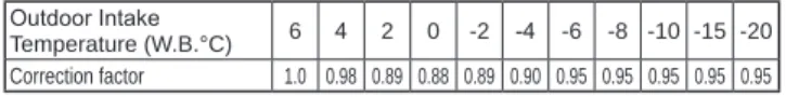
4-4-1. Correction of Heating Capacity for Frost and Defrosting
If heating capacity has been reduced due to frost formation or defrosting, multiply the capacity by the appropriate correction factor from the following table to obtain the actual heating capacity.
Correction factor diagram
(1) Capacity Correction Curve
Outdoor Intake temperature (W.B.°C) 6 4 2 0 −2 −4 −6 −8 −10 −15 −20
[Cooling]
[Heating]
Heating P200 model 11.2
16.8
22.4 29.1
Total capacity of indoor unit
Cooling capacity correction factor
Piping equivalent length (m)
0 5 10 15 20 25 30 35 40 45 50 55 60 65 70 75 80 85 90 0.70
0.75 0.80 0.85 0.90 0.95 1.00
Total capacity of indoor unit
Cooling capacity correction factor
Piping equivalent length (m)
0 5 10 15 20 25 30 35 40 45 50 55 60 65 70 75 80 85 90 0.70
0.75 0.80 0.85 0.90 0.95 1.00
Figure 11
Figure 12
1.5 m
1 m MICROPHONE
UNIT
GROUND 90
80
70
60
50
40
30
20
10 63 125 250 500 1000 2000 4000 8000
OCTAVE BAND SOUND PRESSURE LEVEL, dB (0 dB = 0.0002 µbar)
BAND CENTER FREQUENCIES, Hz
NC-60
NC-50
NC-40
NC-30
NC-20 NC-70
APPROXIMATE THRESHOLD OF HEARING FOR CONTINUOUS NOISE
PUMY-P200YKM2 PUMY-P200YKM2R1 PUMY-P200YKM2-BS PUMY-P200YKM2R1-BS
COOLING MODE HEATING
COOLING SILENT MODE
56 SPL(dB)
61 53
LINE
Operation PUMY-P200YKM2(R1)
PUMY-P200YKM2(R1)-BS
Operating conditions
Ambient tempera- ture
Indoor
DB/WB
27°C/19°C 20°C/ —
Outdoor 35°C 7°C/ 6°C
Indoor unit
No. of connected units
Unit 8
No. of units in operation 8
Model — 25 × 7/50 × 1
Piping
Main pipe
m
5
Branch pipe 2.5
Total pipe length 25
Fan speed — Hi
Amount of refrigerant kg 11.0
Outdoor unit
Electric current A 10.03 9.89
Voltage V 230/400
Compressor frequency Hz 71 86
LEV
opening Indoor unit Pulse 220 300
Pressure High pressure/Low pressure MPa 2.98/0.93 2.18/0.60
Discharge 64.9 53.8
4-6. STANDARD OPERATION DATA (REFERENCE DATA)
5 OUTLINES AND DIMENSIONS
Unit: mm
PUMY-P200YKM2 PUMY-P200YKM2-BS
PUMY-P200YKM2R1 PUMY-P200YKM2R1-BS
6 WIRING DIAGRAM
PUMY-P200YKM2
PUMY-P200YKM2R1
PUMY-P200YKM2-BS
PUMY-P200YKM2R1-BS
7 NECESSARY CONDITIONS FOR SYSTEM CONSTRUCTION
7-1. TRANSMISSION SYSTEM SETUP
012 3 456789 012 3 456789
23 Branch box 001Branch box 006 A Control Indoor unit A (001)
A Control Indoor unit B (002) A Control Indoor unit C A Control Indoor unit A A Control Indoor unit B A Control Indoor unit C (003)(006)(007)(008)
A Control Indoor unit D (004) A Control Indoor unit E (005)
M-NET cable ①M-NET cable shielding wire must be connected to each refrigerant system (outdoorand branch box). ②Set addresses : Outdoor unit......051–100 Branch box...........001–046 ③Outdoor unit has no 100s digit switch. The address automatically become "100" if it is set as "01–50".
PipingSignal line ④Make sure that the wiring between the branch box and indoor unit is properly done, matching with the piping connection.
ABCDEABC MA remote controllerMA remote controllerMA remote controller
MA remote controller
For centralized management 051
Outdoor unitPiping For Branch box/ CITY MULTI indoor unit 1 4
012 3 4
56
78 9 012 3 4
56
9 78
Address SW 012 3 4
56
9 78 012 3 4
56
9 78
Address SW 012 3 4
56
9 78 012 3 4
56
9 78
Address SW 012 3 4
56
9 78 012 3 456789
Address SW
SW1 ON 123456
SW1 ON 123456 CITY MULTI Indoor unit 009
CITY MULTI Indoor unit 010 MA remote controller
CITY MULTI......001–050 061
Outdoor unit For Branch box/CITY MULTI indoor unit 012 3 4
56
9 78
Address SWCITY MULTI Indoor unit 011 CITY MULTI Indoor unit 012 CITY MULTI Indoor unit 013 CITY MULTI Indoor unit 014
CITY MULTI Indoor unit 015 111161
MA remote controller M-NET remote controller
M-NET remote controller
012 3 456789
Address SW 012 3 4
56
9 78
012 3 4
56
9 78
Address SW 012 3 4
56
9 78
012 3 4
56
9 78
Address SW 012 3 4
56
9 78
012 3 4
56
9 78
Address SW 012 3 456789 012 3 456789
Address SW 012 3 456789
Address SW 012 3 4
56
9 78
Address SW 012 3 4
56
9 78
012 3 4
56
9 78
1 1
012 3 4
56
9 78 012 3 456789
■ Applicable outdoor units for this service manual ■ Other CITY MULTI outdoor unit Note: The refrigerant system which includes branch box cannot be operated as a group.
�M-NET remote controller cannot be connected with refrigerant system including branch box. ⑥ Refrigerant systems including branch box cannot be grouped with using M-NET remote controller or system controller. Wireless remote controller Wireless remote controller Wireless remote controller Wireless remote controller
• It is necessary to perform “group settings” and “paired settings” at making group settings of different refrigerant systems (multiple outdoor unit).
(A) Group settings: Enter the indoor unit controlled by the remote controller, check the content of entries, and clear entries, etc.
(B) Paired settings: Used to set the linked operation of a Lossnay unit.
(1) Entering address: Follow the steps below to enter the addresses of the indoor unit using the remote controller.
a) Group settings
• Turning off the remote controller: Press the ON/OFF button to stop operation (the indicator light will go off).
• Changing to indoor unit address display mode: If the FILTER and k buttons on the remote controller are pressed simul- taneously and held for 2 seconds, the display shown in Figure 1 will appear.
• Changing address: Press the temperature adjustment buttons to change the displayed address to the address to be entered.
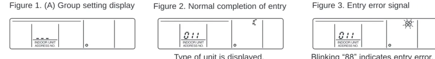
• Entering the displayed address: Press the TEST RUN button to enter the indoor unit with the displayed address.
The type of the unit will be displayed as shown in Figure 2 if entry is completed normally.
If a selected indoor unit does not exist, an error signal will be displayed as shown in Figure 3. When this happens, check whether the indoor unit actually exists and perform entry again.
• Returning to the normal mode after completing entry: Press the FILTER and k buttons simultaneously and hold for 2 seconds to return to the normal mode.
b) Paired Settings
• Turning off the remote controller: Press the remote controller’s ON/OFF button to turn it off (the indicator light will go off).
• Put in indoor unit address display mode: Press the FILTER and k buttons on the remote controller simultaneously and hold for 2 seconds.
Note: The above steps are the same when making group settings (A).
• Changing to the linked operation unit address display state: The display shown in Figure 4 will appear when the a button on the remote control is pressed.
• Displaying the address of the Lossnay unit and linked indoor unit: In this situation, the indoor unit number will be the lowest address of the group. The Lossnay unit will not operate if this setting is incorrect.
Notes:
1. If the temperature adjustment buttons are pressed, the address may be changed to the indoor unit that is to be linked.
2. If the time setting buttons are pressed, the address of the linked units may be changed to the address where it is desired to enter the Lossnay.
• Linking the Lossnay and the indoor unit: The display shown in Figure 5 will appear when the TEST RUN button is pressed.
The indoor unit whose address is displayed and the Lossnay unit with a linked address will operate in a linked manner.
Notes:
1. If it is desired to display the address of the Lossnay in the indoor unit address, display the indoor unit address in the linked unit address, and the above content will also be recorded.
2. Apart from the indoor unit with the lowest address in the group, display and enter the addresses of the other indoor unit that is to be linked with the Lossnay unit.
• Returning to the normal mode after completing entry: Press the FILTER and k buttons on the remote controller simulta- neously and hold for 2 seconds to return to the normal mode.
Figure 1. (A) Group setting display Figure 2. Normal completion of entry Figure 3. Entry error signal
Blinking “88” indicates entry error.
Type of unit is displayed.
(alternating display)
"--" will appear in the unit type display location when an address has been cleared normally.
"88" will appear in the unit type display location when an abnormality has occurred during clearing.
(2) Address check: Refer to section (1) regarding address entry.
a) In making group settings:
• Turning off the remote controller: Press the remote controller's ON/OFF button to stop operation (the indicator light will go off).
• Locate the indoor unit address display mode: Press the FILTER and k buttons on the remote controller simultaneously and hold for 2 seconds.
• Display indoor unit address: The entered indoor units address and type will be displayed each time the button is pressed.
Note that when 1 entry is made, only 1 address will be displayed no matter how many times the w button is pressed.
• Returning to the normal mode after completing check: Simultaneously press the FILTER and k buttons on the remote controller and hold for 2 seconds to return to the normal mode.
b) In making paired settings:
• Turning off the remote controller: Press the remote controller's ON/OFF button to stop operation (the indicator light will go off).
• Put in indoor unit address display mode: Press the FILTER and k buttons on the remote controller simultaneously and hold for 2 seconds.
• Changing to the linked operation unit address display state: Press the a button on the remote control.
• Displaying the address of the indoor unit to be checked: Change the address to that of the indoor unit to be checked by pressing the temperature adjustment buttons .
• Displaying the address of the linked Lossnay unit: Press the w button to display the addresses of the linked Lossnay and indoor unit in alternation.
• Displaying the addresses of other entered units: The addresses of the other entered units will be displayed in alternating fashion after resetting the w button again.
• Returning to the normal mode after completing the check: Simultaneously press the FILTER and k buttons on the remote controller and hold for 2 seconds to return to the normal mode.
(3) Clearing an address: Refer to section (1) regarding the address entry and section (2) regarding checking addresses.
a) In making group settings:
• Turning off the remote controller: The procedure is the same as described in a) under (2) Address check.
• Put in the indoor unit address display mode: The procedure is the same as described in a) under (2) Address check.
• Displaying the indoor unit address to be cleared: The procedure is the same as described in a) under (2) Address check.
• Clearing indoor unit address : Pressing the q button on the remote controller twice will clear the address entry of the dis- played indoor unit, resulting in the display shown in Figure 6.
The display shown in Figure 7 will appear if an abnormality occurs and the entry is not cleared.
Please repeat the clearing procedure.
• Returning to the normal mode after clearing an address: The procedure is the same as described in a) under (2) Address check.
b) In making paired settings:
• Turning off the remote controller: The procedure is the same as described in b) under (2) Address check.
• Put into the indoor unit address display mode: The procedure is the same as described in b) under (2) Address check.
• Put into the linked unit address display mode: The procedure is the same as described in b) under (2) Address check.
• Display the address of the Lossnay unit or the indoor unit to be cleared.
• Deleting the address of a linked indoor unit: Pressing the q button on the remote controller twice will clear the address entry of the displayed indoor unit, resulting in the display shown in Figure 8.
• Returning to the normal mode after clearing an address: The procedure is the same as described in b) under (2) Address check.
Figure 7. Display when an abnormality has occurred during clearing Figure 6. Display after address has been
cleared normally
Figure 8. Display after address has been cleared normally
"88" will appear in the room temperature display location.
"--" will appear in the room temperature display location.
7-3-1. Connection without Branch box
PUMY-P200YKM2 PUMY-P200YKM2-BS PUMY-P200YKM2R1 PUMY-P200YKM2R1-BS
Thermistor(TH7)
<Ambient>
Check valve
<Low pressure>
Ball valve
Strainer 4-way valve
Accumulator
High pressure switch(63H) Check valve
<High pressure>
Compressor
Distributor
Thermistor(TH3)
<Outdoor liquid pipe>
LEV-A HIC
Oil separator Solenoid
Valve(SV1) Service port
High pressure sensor(63HS)
Low pressure sensor(63LS)
Capillary
tube Thermistor(TH4)
<Compressor>
Thermistor(TH6)
<Suction pipe>
Thermistor(TH2)
<HIC pipe>
Refrigerant gas pipe
Strainer
Strainer Strainer
Capillary tube
LEV-B Strainer
Strainer
Service port Refrigerant liquid pipe
Stop valve
Strainer Strainer
Refrigerant piping specifications <dimensions of flared connector>
Item
Capacity Liquid piping Gas piping
Indoor unit
P10, 15, 20, 25, 32, 40, 50
ø6.35 <1/4>
ø12.7 <1/2>
P63, 80, 100, 125, 140
ø9.52 <3/8>
ø15.88 <5/8>
P200
ø9.52 <3/8>
ø19.05 <3/4>
Outdoor unit P200
ø9.52 <3/8>*
ø19.05 <3/4>
* Use ø12.7 in case of farthest piping length is longer than 60m.
Capillary tube for oil separator: ø2.5 × ø0.8 × L800 Capillary tube for solenoid valve: ø4.0 × ø3.0 × L500
Unit: mm <in>
Unit: mm