SAFETY PRECAUTION
To repair refrigeration systems, (1-3) through (1-7) must be completed before working on the systems. If electrical components are changed, they must be fit for purpose and to the correct specifications. This should be communicated to the owner of the equipment so that all parties are informed.
Before refilling the system, it should be pressure tested with the appropriate purge gas. The appliance must be labeled stating that it has been deactivated and drained of refrigerant. The recovered refrigerant will be returned to the refrigerant supplier in the appropriate recovery cylinder and the appropriate waste transfer note will be adjusted.
The evacuation process will be carried out before the compressor is returned to the suppliers. Only electrical heating to the compressor body will be used to accelerate this process.
FEATURES
SPECIFICATIONS
DATA
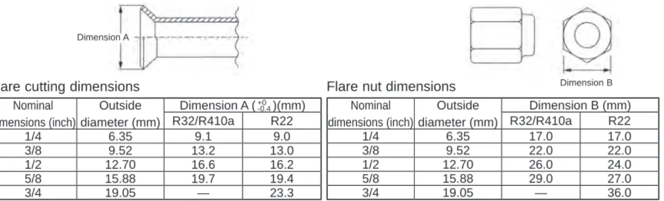
OUTLINES AND DIMENSIONS
WIRING DIAGRAM
Always use an earth leakage circuit breaker compatible with higher harmonics as this unit is equipped with an inverter. However, between S3 and S1 these connections are NOT electrically isolated by a transformer or other device. The indoor/outdoor unit power cords and connection cords should not be lighter than polychloroprene sheathed flexible cord.
In the case of control A wiring, there is a high voltage potential at the S3 terminal caused by the circuit design that has no electrical isolation between the power line and the communication signal line. If the insulator must be used between the indoor unit and the outdoor unit, please use the 3-pole type.
WIRING SPECIFICATIONS
If the optional indoor power supply terminal kit is used, change the wiring of the indoor unit's electrical box by referring to the figure on the right and the DIP switch settings of the outdoor unit's control board. Label attached next to each connection diagram for indoor and outdoor units Outdoor unit DIP switch settings (when using only indoor/outdoor unit separate power supplies). Power supply cables and indoor unit/outdoor unit connection cables should not be lighter than polychloroprene coated flexible cables.
Set the lowest number in the group for the outdoor unit whose refrigerant address is "00" as its M-NET address. In group B, the M-NET address of the outdoor unit whose refrigerant address is “00” is not set to the minimum in the group. Taking group A as a good sample, set the smallest M-NET address in the group for the outdoor unit whose refrigerant address is "00".
For A-control models, the M-NET address and refrigerant address need to be set for the outdoor unit only. To build a central control system, the M-NET address setting should be performed only on the outdoor unit.
REFRIGERANT SYSTEM DIAGRAM
However, this is not a problem with a product, because the control valve itself generates the sound when the pressure difference is small in the refrigerant circuit. If "CENTRALLY CNTROLLED" is displayed, the coolant collection (pumping down) cannot be completed normally. Press the pump-down SWP switch (push button type) on the control board of the outdoor unit.
However, even if the unit is stopped and the pump-down SWP switch is pressed less than 3 minutes after the compressor has stopped, the refrigerant collection cannot be performed. Because the unit automatically stops in about 3 minutes when the refrigerant collection operation is completed (LED1 off, LED2 on), be sure to close the gas ball valve quickly. If the cooling recovery operation is completed normally (LED1 off, LED2 on), the unit will remain stopped until the power supply is turned off.
In this case, use refrigerant recovery equipment to recover all the refrigerant in the system. 7 Turn off the power (circuit breaker), remove the gauge manifold, and then disconnect the refrigerant lines.
TROUBLESHOOTING
FUNCTION SETTING
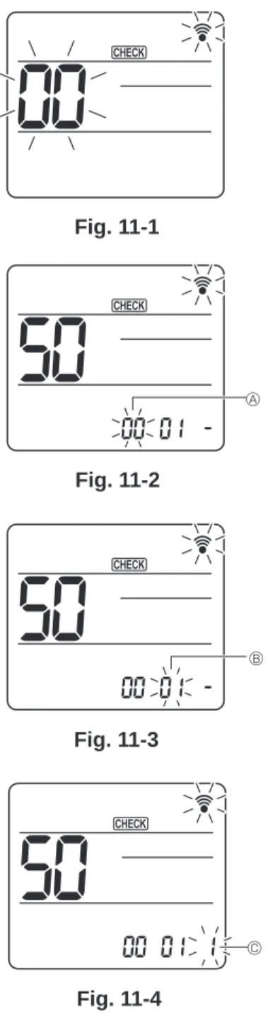
2 Set the indoor unit refrigerant addresses and unit numbers with the F1 to F4 buttons, and then press the [ ] button to confirm the current setting. 4 Use the F1 or F2 button to move the cursor to select the mode number, and change the setting number with the F3 or F4 button. lt; Check the indoor unit No.>. 5 When the settings are completed, press the [ ] button to send the setting data from the remote controller to the indoor units.
Refer to the indoor unit installation manual for detailed information about the initial settings, mode numbers, and setting numbers for the indoor units. Check mode is the mode entered when you press the CHECK button twice to display. Note: When you enter the function selection mode in the wireless remote control operation area, the unit automatically ends the function selection mode if nothing is input for 10 minutes or more.
Function selection using the wireless remote controller is only available for refrigeration systems with wireless function. If the unit number is set to AL, all indoor units in the same refrigerant system will start fan operation at the same time. Point the wireless remote controller at the receiver of the indoor unit and press the button.
Point the wireless remote control towards the sensor of the indoor unit and press the button. The sensor operation indicator will flash and beeps will be heard to indicate the setting number. Note: Do not use the wireless remote control for 30 seconds after completing the function setting.
Starts this operation from the status of the remote controller display turned off.) [CHECK] lights up and flashes. Point the wireless remote controller at the receiver of the indoor unit and press the button. Point the wireless remote controller at the indoor unit sensor and press the button.
MONITORING THE OPERATION DATA BY THE REMOTE CONTROLLER
Certain indoor/outdoor combinations do not have the request code feature; therefore no request codes are displayed. Compressor-Operating current (rms) Compressor-Accumulated operating time Compressor-Number of operating times Discharge temperature (TH4). Outdoor unit - Liquid pipe 2 temperature Outdoor unit-2-phase pipe temperature (TH6) Outdoor unit-Outdoor temperature (TH7) Outdoor unit-Heating temperature (TH8) Discharge superheat (SHd).
Indoor unit - Liquid pipe temperature (Unit No. 1) Indoor unit - Liquid pipe temperature (Unit No. 2) Indoor unit - Liquid pipe temperature (Unit No. 3) Indoor unit - Liquid pipe temperature (Unit No. 4) Indoor unit - Condition/Eva. Indoor unit-Control status Outdoor unit-Control status Compressor-Frequency control status Outdoor unit-Fan control status Actuator output status Error content (U9). Display of replacement/wash operation execution Outdoor unit - Microprocessor version information Outdoor unit - Microprocessor version information (sub no.).
Compressor-Operating current at the time of failure Compressor-Accumulated operating time at the time of failure Compressor-Number of operating hours at the time of failure Discharge temperature at the time of failure. Outdoor unit - Liquid pipe 1 temperature (TH3) at the fault time Outdoor unit - Liquid pipe 2 temperature at the fault time Outdoor unit-2-phase pipe temperature (TH6) at the fault time Outdoor unit-Outside air temperature (TH7) at failure time Outdoor unit-Heatsink temperature (TH8) at failure time Discharge superheat (SHd) at failure time. Indoor - Liquid pipe temperature at the time of failure Indoor - Cond/Eva. pipe temperature at the time of failure Indoors at the time of failure.
Indoor unit-Capacity setting information Indoor unit-SW3 information. indoor control board side) setting Indoor unit-SW5 information. Display Discharge temperature Condensation temperature Freezer Cooler temperature prevention overheating prevention protection control overheating prevention 0. Maintenance data, such as the indoor/outdoor unit heat exchanger temperature and compressor operation current can be displayed with "Smooth maintenance".
EASY MAINTENANCE FUNCTION
Depending on the combination with the outdoor unit, this may not be supported by some models. 4 Coolant/heat exchanger temperature COOL °C HEAT °C 5 Coolant/discharge temperature COOL °C HEAT °C 6 Air/outside air temperature COOL °C HEAT °C (Air/discharge temperature) COOL °C HEAT °C. Air/intake air temperature COOL °C HEAT °C (Air/discharge temperature) COOL °C HEAT °C 8. Coolant/heat exchanger temperature COOL °C HEAT °C.
The filter uptime is the time that has elapsed since the filter was reset. 7 Indoor intake air temperature) – (8 Indoor heat exchanger temperature) Is “D000” displayed steadily on the remote control. In heat mode, the operating condition may change due to the formation of frost on the external heat exchanger.
7 Indoor intake air temperature)— (8 Indoor heat exchanger temperature) (8 Indoor heat exchanger temperature) — (7 Indoor intake air temperature).
DISASSEMBLY PROCEDURE
