The declaration applies only to product in the condition in which it was delivered and installed in the facility in accordance with the enclosed installation instructions. EN 61000-6-3 Electromagnetic compatibility (EMC) – Part 6-3: Generic standards – Emission standards for residential, commercial and light industrial environments. Ensure that the mains supply to the unit is disconnected before carrying out any maintenance or electrical work.
All electrical connections and maintenance work must be carried out by an authorized installer and in accordance with local rules and regulations. Installation of the unit and the complete ventilation system must be carried out by an authorized installer and in accordance with local rules and regulations. Even though the power supply to the unit has been disconnected, there is still a risk of injury due to rotating parts that have not come to a complete stop.
The manual contains basic information and recommendations regarding design, installation, commissioning and operation to ensure correct operation of the unit without errors. The key to proper and safe operation of the unit is to read this manual carefully, use the unit in accordance with the guidelines given, and follow all safety requirements.
General
Transport and storage
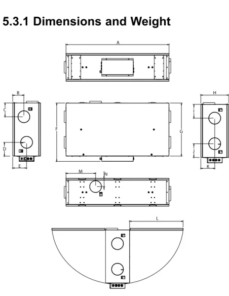
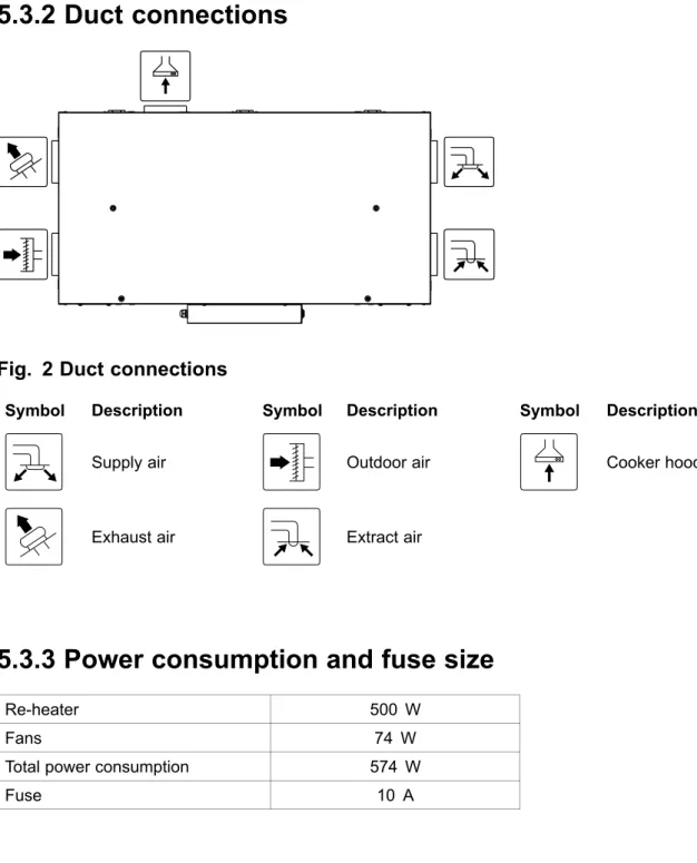
Technical data
To ensure proper and error-free operation, it is important that the unit is installed according to these instructions.
Unpacking
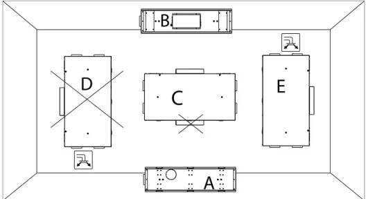
Where/how to install
Installing the unit
Installation procedure
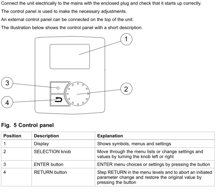
Control panel
Temp Illustrates the current supply temperature set point (from completely empty to full symbol). It is not recommended to activate manual fan stop (set fan to OFF) in standard households. If manual fan stop is activated, the unit should be fitted with dampers in the exhaust and fresh air ducts to avoid cold drafts and the risk of condensation when the unit has been stopped.
Start up wizard
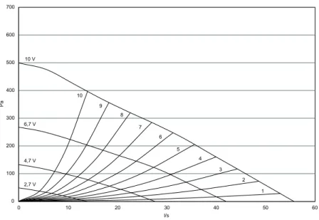
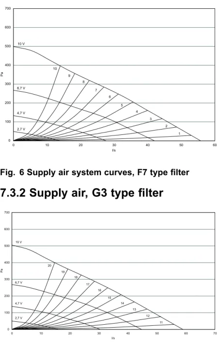
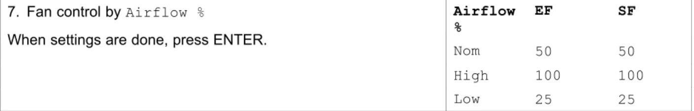
The factory-fitted filters are of filter quality F7 for the supply air and G3 for the exhaust air filter. Here it is possible to change the Nominal/High/Low air volume on the Extraction fan (EF) and the supply fan (SF). Enter the service menu by selecting the service symbol in the display and pressing ENTER.
Use the SELECT button for each digit and confirm with the ENTER button after each set digit and choose NO to not lock the system.
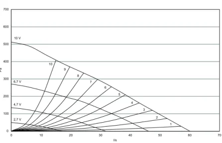
System curves
Airflow settings
Defrost level settings
Use the SELECT button for each digit and confirm with the ENTER button after each set digit and select "NO" for the system not to be locked.
Programming the Week schedule
Ext/Force run
Extra functions
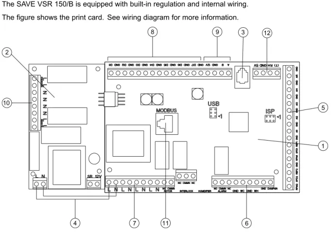
Electrical connections
4 Power connection between main print card and print card with electric heater 5 Connections for AI 1-5 (temperature sensors) and motor control. 6 Connections for external connections 7 Connections for network connections 8 Connections for digital inputs (DI 1-7) 9 Connections for internal control panel. The connection terminals for external equipment can be found on the main printer card inside the electrical connection box.
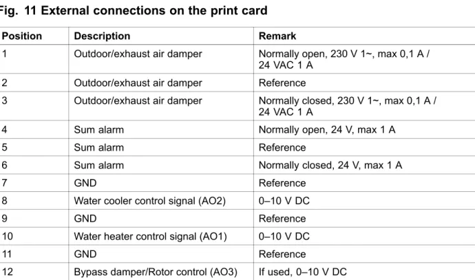
External connections on the unit
Setting the temperature
Manual setting of airflow
Manual and automatic summer mode
The unit will automatically switch between winter operation with heat recovery and summer operation without heat recovery.
Cool recovery
Service menu overview
Use this dialog box to program the extended time you want the unit to operate under operating conditions other than the weekly schedule. Set the day of the week and the time interval for when you want the unit to be in ON mode. Use this dialog box to define the ON and OFF function of the fans in a weekly schedule.
Use this dialog box to see how the fans performed during the time (h) they were active. Choose between levels to see the time in hours that fans were active at different levels. If the preheater is activated and the heat exchanger control is set to "On/Off", it is highly recommended to select defrost level 0 to avoid conflicts with the defrost functions.
Set if it should be possible to switch off the fans in the unit manually from the control panel. If Yer selected, the fans can be turned off by turning the SELECTION knob to empty fan. It is also possible to set how you want the fans to react to 3 different digital inputs when switched on.
Set the supply air fan (SF) and extract air fan (EF) separately to off, low, nominal or high for digital inputs 1–3 Set a predefined delay for the input signal. Heat exchanger operating with the adjusted setpoint and an active reheater has support control for the lowest setpoint. Use this dialog to configure the intensity of the extract air humidity control, which helps to prevent moisture transfer to the supply air.
Use this dialog to set how aggressively you want the defrost function to work (see section 7.5). These settings are only present if the heat exchanger controller type is set to On/Off.
Warnings
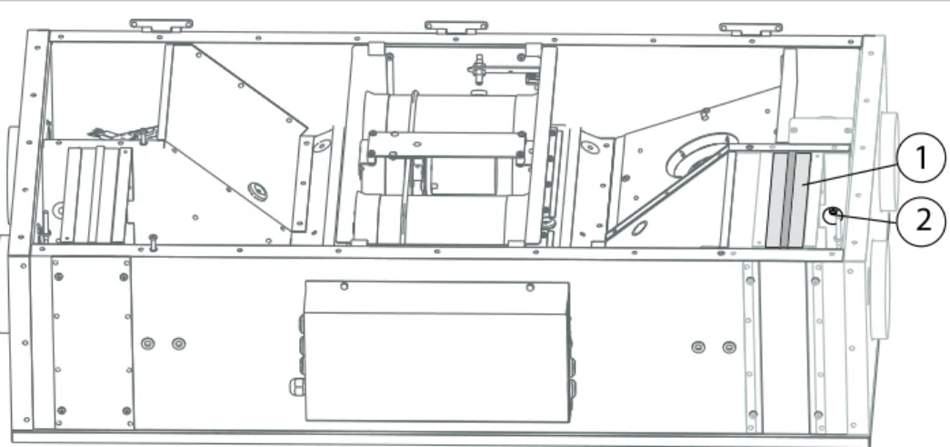
Internal components
Component descriptions
If the supply air temperature is low, it may mean that the overheating protection has been triggered. The reheater battery (optional), which can be purchased as an accessory, can be controlled by the analog output WH (0-10 V DC). The water heater uses AI 4 for frost protection (OT, overheating protection, FPS changes, frost protection in the menu).
The anti-freeze sensor should be a surface mounted sensor on the return water pipe. The supply air sensor (SS) on AI 1 must be replaced with a duct sensor, which can be purchased as an accessory. If a battery for additional water heating is installed, we strongly recommend that you also install an outside air damper with a spring return drive.
A water chiller (optional) can be purchased as an accessory and is controlled by the unit. If a water cooler is installed, the supply air sensor (SS) on AI 1 must be replaced with a duct sensor, which can be purchased as an accessory.
Trouble shooting
Check the analog inputs in the service menu to verify that the temperature sensors are OK (chapter 9.5). Go to Functions > Analog Input and check the temperature readings from the temperature sensors.
Alarm list
For units with external heaters: For reset, see the manual for the external electric heater. If the heat exchanger is still rotating, check that the quick connector for the sensor is connected and that there is an air gap of 5-10 mm between the sensor and the magnet. Pb Fail Fault related to the relay card for the electric reheater (if installed and activated).
If the reheater is configured and the frost protection has failed, an additional protection function is activated when the supply air temperature is below 5 °C and the outdoor air temperature is below 0 °C.
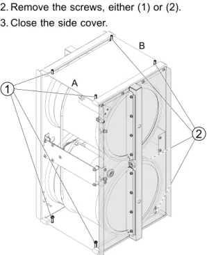
Replacing rotor drive belt
If heat exchanger cables are not visible, they are behind the filter in the exhaust air chamber (4). If the unit is mounted with a side cover facing down, do not remove the screws in the slots. Depending on how the unit is installed, it may not be necessary to remove the heat exchanger package to temporarily repair a broken drive belt if the belt pulley is accessible.
Pull the drive belt onto the pulley and use tape to secure the drive belt to the second heat exchanger. Pull the drive belt onto the pulley and rotate the alternator by hand. If the pulley is not available, the heat exchanger package must be removed to temporarily repair a broken drive belt.