SAFETY PRECAUTION
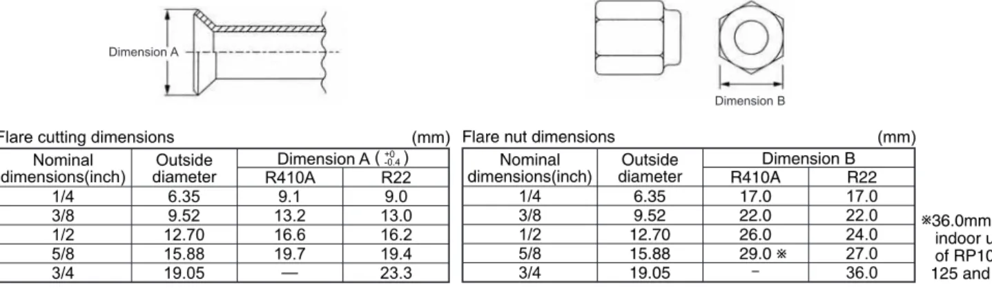
The incineration must be carried out in such a way that the incineration corresponds to the dimension for R410A. Use the end nut supplied with the indoor and outdoor units. In case the existing pipes were used for a gas or oil heat pump system, be sure to clean the pipes for HRP models. Although the refrigerant piping for R410A is the same as for R22, special tools are required to prevent mixing with another type of refrigerant.
Therefore, to increase air tightness and intensity, the cross-sectional dimensions of the copper pipes for R410A were determined separately from the dimensions for other refrigerants, as shown below. The B end nut dimension for R410A has also been partially modified to increase the intensity as shown below. Exclusive tool for R410A Exclusive tool for R410A Tool for HFC refrigerant Exclusive tool for R410A Exclusive tool for R410A Ester oil and alkylbenzene oil (minimum quantity).
Exclusive tool for R410A. Tools exclusive to R410A Tools for other refrigerants can be used if equipped with reverse flow control adopter Tools for other refrigerants can be used by adjusting burn dimension Tools for other refrigerants can be used Tools for other refrigerants can be used Tools for other refrigerants can be used Tools for other refrigerants can be used Tools for other refrigerants can be used. Use the new tool as the exclusive tool for R410A.): Tools for other refrigerants can be used under certain conditions.
FEATURES
SPECIFICATIONS
DATA
OUTLINES AND DIMENSIONS
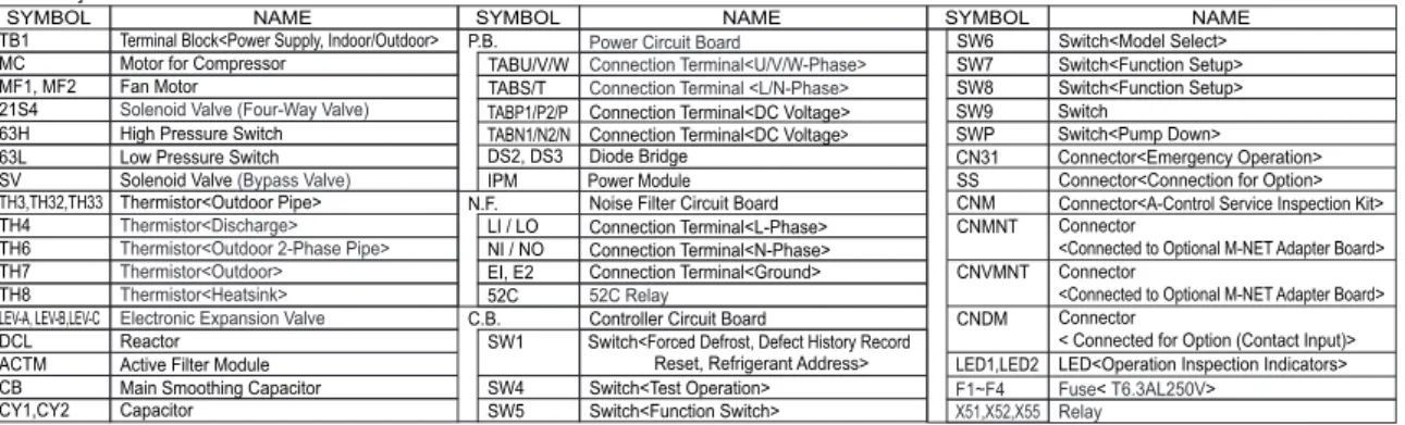
WIRING DIAGRAM
WIRING SPECIFICATIONS
If the optional indoor power supply terminal kit is used, change the indoor unit power box wiring according to the figure on the right and the DIP switch settings on the outdoor unit control board. Label affixed near each wiring diagram for the indoor and outdoor units Outdoor unit DIP switch settings (only when using separate indoor/outdoor unit power supplies). Power supply cables and indoor unit/outdoor unit connection cables must not be lighter than polychloroprene sheathed flexible cable.
Set the lowest number in the group for the outdoor unit whose refrigerant address is "00" as its M-NET address. In A control models, M-NET address and refrigerant address must be set for the outdoor unit only. Similar to CITY MULTI system, it is not necessary to set the address of outdoor unit and remote controller.
To build a central control system, the M-NET address setting should only be done on the outdoor unit. The address number can be set using rotary switches (SW11 for single digits and SW12 for tens digits) located on the M-NET board of the outdoor unit.
REFRIGERANT SYSTEM DIAGRAM
When power is supplied, make sure "CENTRALLY CONTROLLED" is not displayed on the remote control. After the liquid stop valve is closed, set the SWP switch on the outdoor unit control board to ON. However, the refrigerant recovery operation cannot be performed until the compressor stops even if the unit is stopped.
When re-using existing pipes that carried R22 refrigerant for the HRP71, HRP100 and HRP125 models, a replacement operation must be carried out before the test is carried out. Set DIP switch SW8-2 on the control panel of the outdoor unit to ON to start the replacement process. During the replacement process, TEST RUN is displayed on the remote controller, and LED1 (green) and LED2 (red) on the control panel of the outdoor unit flash together.
By using the DIP switch SW4 on the outdoor unit control board, the test run can be started and ended and the operation mode (cooling/heating) can be set. To change the test run mode, stop the unit with SW4-1, change the operating mode and restart the test run with SW4-1.).
TROUBLESHOOTING
Point the remote controller at the sensor on the indoor unit and press the HOUR button. Point the remote controller at the sensor on the indoor unit and press the ON/OFF button.
FUNCTION SETTING
When setting functions for an indoor unit in an independent system, set the unit number to 01 referring to Setting the indoor unit number of Operating Procedure. When setting functions for a simultaneous twin indoor unit system, set the unit number to 01 to 02 for each indoor unit in the case of selecting different functions for each unit with reference to the setting of the indoor unit number of Operating Procedure. When setting the same functions for an entire simultaneous two-indoor unit system, set refrigerant address to AL (07 in the case of wireless remote controller) referring to the setting of the indoor unit number of Operating Procedure.
Press the [ CLOCK] buttons ( and ) to select the unit number of the indoor unit for which you want to perform function selection. When the refrigerant address and unit number are confirmed by pressing the MODE button, the corresponding indoor unit fan operation will start. In this case, the refrigerant address and unit number may be incorrect, so repeat steps and set the correct one.
Setting number display. Setting number 1 = indoor unit operation average Setting number 3 = TEST of built-in remote control sensor. Note: When you switch to the function selection mode in the wireless remote controller's operating range, the unit will automatically exit the function selection mode if there is no input for 10 minutes or more. Function selection using wireless remote control is only available for refrigerant system with wireless function.
Point the wireless remote control at the receiver of the indoor unit and press the button. Point the wireless remote control at the receiver of the indoor unit and press the button. If a unit number is entered that cannot be recognized by the unit, 3 beeps of 0.4 seconds will be heard.
Point the wireless remote control at the sensor of the indoor unit and press the button. The setting of the following remote control functions can be changed using the remote control function selection mode. When the remote control is connected to the unit that has automatic operation mode, the following settings can be made.
MONITORING THE OPERATION DATA BY THE REMOTE CONTROLLER
Certain indoor/outdoor combinations do not have a question code function; therefore no request codes are displayed. Outdoor unit - Liquid pipe 2 temperature Outdoor unit - 2-phase piping temperature (TH6) Outdoor unit - Outdoor air temperature (TH7) Outdoor unit - Heatsink temperature (TH8) Discharge superheat (SHd). Indoor Unit - Liquid Line Temperature (Unit No. 1) Indoor Unit - Liquid Line Temperature (Unit No. 2) Indoor Unit - Liquid Line Temperature (Unit No. 3) Indoor Unit - Liquid Line Temperature (Unit No. 4) Indoor Unit -Cond./Eva.
Indoor unit - Control mode Outdoor unit - Control mode Compressor - Frequency control mode Outdoor unit - Fan control mode Actuator output state Error content (U9). Outdoor unit-Capacity setting display Outdoor unit-Setting information Outdoor unit-SW1 setting information Outdoor unit-SW2 setting information Outdoor unit-SW4 setting information Outdoor unit-SW5 setting information Outdoor unit-SW6 setting information Outdoor unit-SW7 setting information Outdoor unit-SW8 setting information Outdoor unit-SW9 setting information Outdoor unit-SW10 setting information. Display of replacement/washing operation execution Outdoor unit-Microcomputer version information Outdoor unit-Microcomputer version information (sub no.).
Compressor-Operating current at time of error Compressor-Added operating time at time of error Compressor-Number of operating times at time of error Discharge temperature at time of error. Outdoor unit - Liquid line 1 temperature (TH3) at the time of the failure Outdoor unit - Liquid line 2 temperature at the time of the failure Outdoor unit - 2-phase line temperature (TH6) at the time of the failure Outdoor unit - Outdoor air temperature (TH7) at the time of the failure Outdoor unit heat sink temperature (TH8) at time of error Discharge superheat (SHd) at time of error. Thermostat ON time until operation stops due to an error Indoor - Liquid line temperature at the time of the error Indoor 2-phase pipe temperature at the time of the error Indoor at the time of the error.
Indoor unit- Model setting information Indoor unit- Capacity configuration information Indoor unit- Information SW3. indoor control panel setup) Indoor unit information-SW5. The state of determining the capacity of the screen. internal control panel setting)] (Request code 165 ) Data display.
EASY MAINTENANCE FUNCTION
Cooler/Heat Exchanger Temp Cool Heat/Discharge Temp Cool Heat Air/Outside Air Temp Cool Heat (Air/Discharge Temp) Cool Heat. Indoor intake air temperature) – (Indoor heat exchanger temperature) Is “D000” displayed steadily on the remote control. In heat mode, the operating condition may change due to the formation of frost on the external heat exchanger.
Indoor intake air temperature)— (Indoor heat exchanger temperature) ( Indoor heat exchanger temperature) — ( Indoor intake air temperature) [ Discharge temperature] – [ Outdoor heat exchanger temperature). This air conditioner (outdoor unit) can detect refrigerant leakage that may occur during long-term use. To enable leak detection, the following settings are necessary to allow the unit to remember the initial state (initial refrigerant amount).
1.How to select "Refrigerant leak detection" mode Detection is possible regardless of unit operation (ON or OFF). The initial learning of the leak detection is always performed once after the new installation or data reset. When the unit is removed and reinstalled or refrigerant is added further, "Initial learning" must be performed again by following the procedure.
After resetting the data, please turn the pin of CN31 and SW4-1 to original (OFF) position. 1.In the following condition, the operation cannot be stabilized and the judgment of cheking operation may not be accurate. 2. Please check the operation and unit status, when the operation is not stabilized after more than 45 minutes.
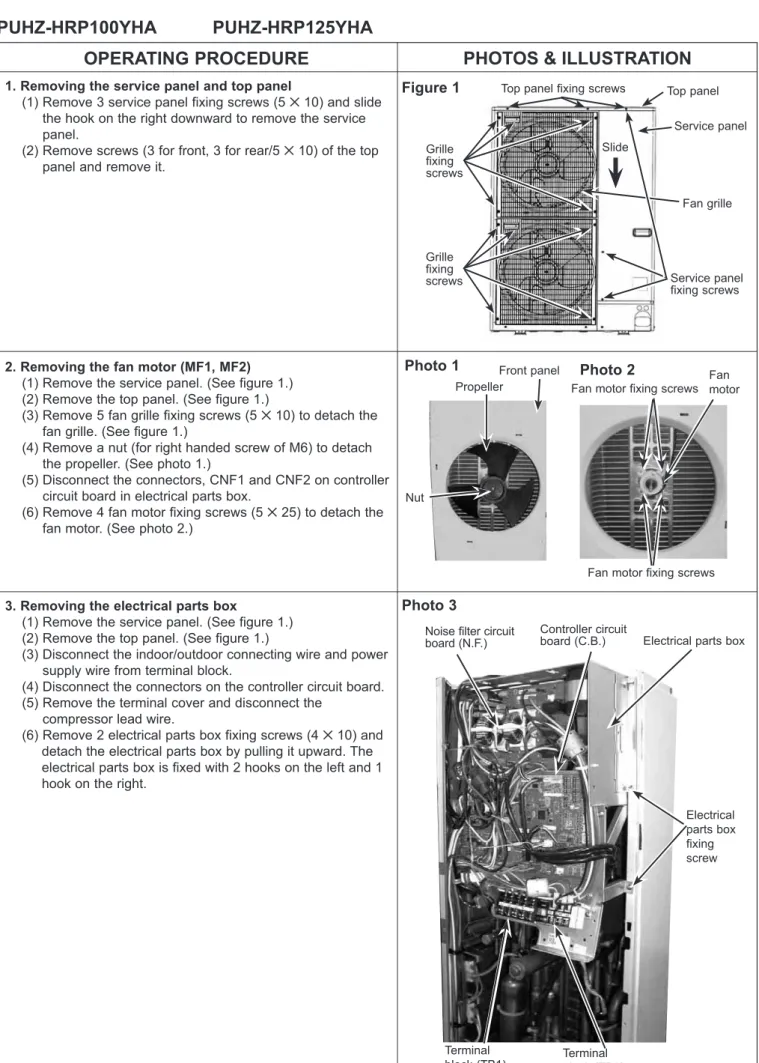
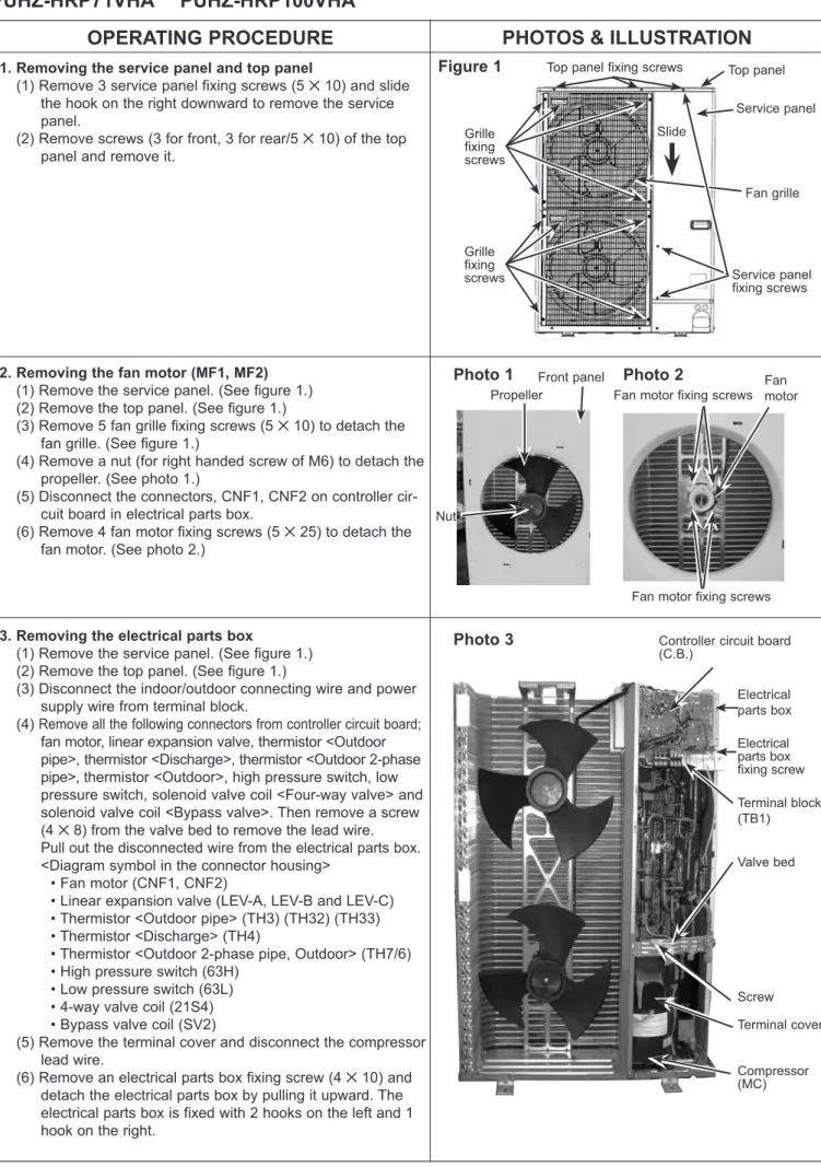
DISASSEMBLY PROCEDURE
Removing the high pressure switch (63H) and the low pressure switch. 3) Remove the 3 right side panel (510) fixing screws at the back of the unit and remove the right side panel.