Appears when the built-in thermistor on the remote control is activated to monitor the room temperature (a). Most settings (except ON/OFF, mode, fan speed, temperature) can be made from the menu screen. Check code, error source, refrigerant address, unit model, serial number, contact information (dealer phone number) can be displayed.
Energy Saving Auto return Use this option to operate the units at the preset temperature after performing energy saving operation for a specified period of time. Manual Vane Angle Use this option to set the vane angle for each vane in a fixed position. Auto mode You can select whether or not you want to use the AUTO mode using the button.
Restriction setting • Outdoor unit silent mode setting • Night setting Language selection Use to select the desired language. Request code (**): You can check the details of the operation data, including the temperature of each thermistor and the error history.
5 NOISE CRITERION CURVES
6 OUTLINES AND DIMENSIONS
WIRING DIAGRAM7
8 REFRIGERANT SYSTEM DIAGRAM
Actions to be taken for service, which depend on whether or not the problem recurs in the field, are summarized in the table below.
9-1. TROUBLESHOOTING
TROUBLESHOOTING9
In approx. 2 minutes after startup, operation of the remote control is not possible due to system startup. 4 Replace the indoor controller board if it is shorted between 3-4 of the drain float switch connector CN4F and the abnormality occurs again. 1–4 Check the tube
1 Abnormal if the indoor control board cannot receive data normally from the remote control board or other indoor control board for 3 minutes. 3 Incorrect remote control connection 4 Defective broadcast receiver. remote control circuit 5 Defective broadcast receiver. the internal cooler controller board circuit addresses "0". Note: Other indoor controller boards may be defective in case of dual triple indoor unit system.
Indoor/outdoor unit communication error (signal reception error) 1 Abnormal if indoor control board. 6 minutes after power on, it cannot receive any signal normally. Abnormal when data cannot be read normally from the persistent memory of the internal controller board. board 1 Replace the internal controller board.
9-4. TROUBLESHOOTING OF PROBLEMS
3 Normal operation (Each connector on the swing motor side is disconnected or set the fixed wheels by wired remote controller.). 2) LED2 on internal control board blinks. 1 Check the connection of remote controller wires in the case of two-triple indoor unit system. When the same problem occurs even if indoor control board is replaced, replace wireless remote control board.
9-5. EMERGENCY OPERATION
9-6. HOW TO CHECK THE PARTS
Do not pull the connector (CNMF) for the motor with the power supply on. Causes internal controller circuit board and fan motor problems.) Self-check. Remove the fan motor (Remove the fan motor connector CNMF) and measure the voltage on the indoor controller circuit board. Check the DC fan motor method (fan motor / indoor controller circuit board). loose connector, insertion failure) No.
Note: If the indoor fan does not work after replacing the indoor controller board, also replace the fan motor. Note: If the indoor fan does not work after replacing the fan motor, also replace the indoor controller board.
9-7. TEST POINT DIAGRAM
Indoor controller board
The pair number settings of the wireless remote controller and indoor control PCB (J41/J42) are given in the table on the left. in the table indicates that the jumper wire is disconnected.).
9-8. FUNCTIONS OF DIP SWITCH AND JUMPER WIRE
10 SPECIAL FUNCTION
10-2. ELECTRICAL CIRCUIT (Controller board and wiring diagram (Panel))
10-2-1 DIP SW
Problem Possible Cause Corrective Action Intake grille not working. with the operation of the remote control. Inlet grille repeats rising and lowering several times while being placed in the correct position. Lower the intake grille again and check that the filter is installed in the correct position.
10-3. TROUBLESHOOTING
Check the following points
When the unit is restarted to operate after the power has been turned off or turned off, the unit that was in operation will start to operate. How to set rotation function (Back support function, 2nd stage cut-in function)" and set the request code No. which is not the same as the current one, then again set the previous request code No. 2) 2nd stage cut-in function Outline of functions. When the 1st unit cannot provide sufficient capacity for exceptionally high demand conditions and the actual room temperature reaches setpoint (*), the 2nd unit starts operating in conjunction with the 1st unit.
As soon as the actual room temperature drops to 4°C below setpoint (*), the 2nd unit automatically stops operation. ROTATION FUNCTION (AND BACK-UP FUNCTION, 2ND STAGE CUTTING FUNCTION). 1) Rotation function (and Backup function). This function is only available through the grouping control system (INDOOR UNIT : OUTDOOR UNIT=1:1) of 2 refrigerant groups.
The main indoor unit must be connected for the wired remote controller, and the transmission line (TB5) for the main and sub unit must also be connected. This function cannot be set via the wireless remote control.). Setting the rotation function (Backup function, 2nd stage enable function) You can set these functions with a wired remote controller.
NOTICE
9 Press the F3 or F4 button to set the desired request code number. Data is collected and displayed.
DISASSEMBLY PROCEDURE11
OPERATING PROCEDURE PHOTOS & ILLUSTRATIONS
Removing the filter
Removing the electrical box cover
OPERATING PROCEDURE PHOTOS
Removing the indoor controller board (I.B)
Removing the electrical box
Removing the fan motor (MF)
Cross section diagram
- Removing the turbo fan
- Removing the drain pan
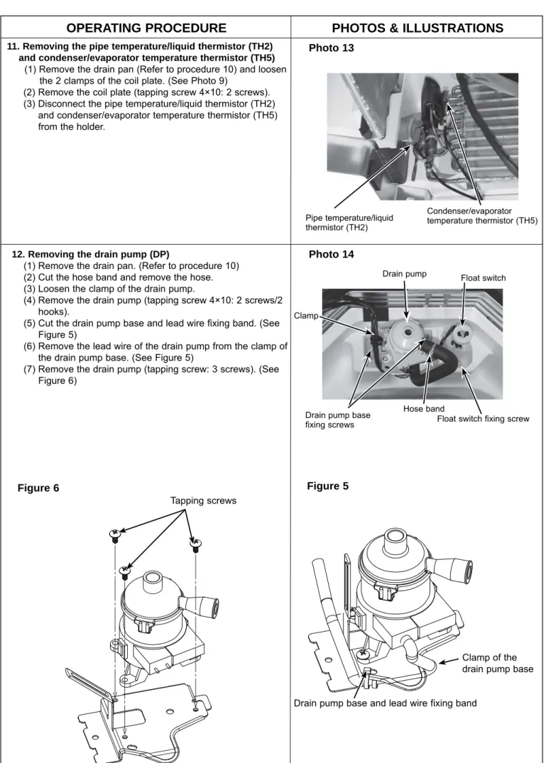
- Removing the pipe temperature/liquid thermistor (TH2) and condenser/evaporator temperature thermistor (TH5)
- Removing the float switch (FS)
Remove the pipe temperature/liquid thermistor (TH2) and condenser/evaporator temperature thermistor (TH5) and condenser/evaporator temperature thermistor (TH5). U-shaped part of the float switch base 14. 4) Remove the heat exchanger mounting screws (tapping screw 4×10: 2 screws).