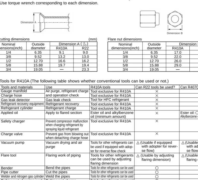
Although the refrigerant piping for R410A is the same as for R22, exclusive tools are necessary to avoid mixing with different kinds of refrigerant. Therefore, in order to increase the air density and intensity, the flare cutting dimension of the copper tube for R410A has been specified separately from the dimensions for other refrigerants as shown below.
-15). wWhen using an optional air outlet guide installed for upward airflow, the distance is 1500 mm or more. In the case of less than 200 mm (eg Ais 100 mm), the replacement of the junction box from a maintenance hole becomes difficult (only the replacement of a circuit board, linear expansion valve coils, sensors and drain tank is possible).
3-5. SIMPLIFIED PIPING SYSTEM
Piping connection size
Rated cooling capacity Rated power consumption w1 Operating current w1 Operating power factor w1 Starting current (outdoor unit) Rated heating capacity Rated current consumption w1 Operating current w1 Operating power factor w1 Starting current (outdoor unit).
Outdoor unit : MXZ-8A140VA MXZ-8A140VA 1 MXZ-8A140VA 2 MXZ-8A140VA 3
Width Depth Height Branch (indoor side) Main (outdoor side) To indoor unit To outdoor unit. If the pipe connection size of the junction box does not match the pipe connection size of the indoor units, use optional joints of different diameter (deformed) on the side of the junction box. Connect the deformed joint directly to the side of the junction box.).
5-1. CAPACITY AND CHARACTERISTICS
1) Cooling mode
Outdoor unit current (A) Unit A Unit B Unit C Unit D Unit E Unit F Unit A Unit B Unit C Unit D Unit E Unit F 230V 240V 220V Number of operated indoor unit.
5-2. CORRECTING COOLING AND HEATING CAPACITY
Corrected pipe length = (Actual pipe length between outdoor unit and farthest indoor unit) + (0.30 number of bends in the pipe) (m).
UNIT
GROUND5-3. NOISE CRITERION CURVES
MXZ-8A140VA MXZ-8A140VA 1
MXZ-8A140VA MXZ-8A140VA 1 MXZ-8A140VA 2
MXZ-8A140VA 3
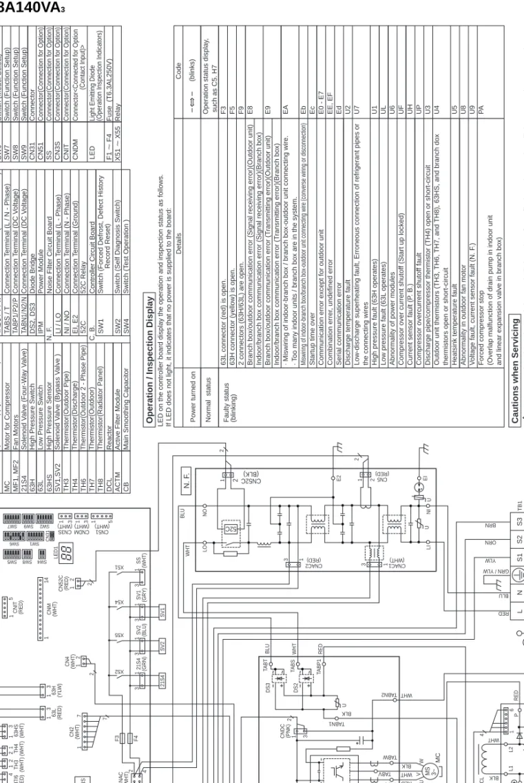
Terminal Block (Power Supply, Branch) Motor for Compressor Fan Motors Solenoid Valve (Four Way Valve) Solenoid Valve (Hot Gas Bypass) Solenoid Valve (Oil Return Bypass) High Pressure Sensor High Pressure Switch Low Pressure Switch Thermistor (Outdoor Pipe) Thermistor (Discharge) Thermistor (Outdoor 2 - Phase Pipe) Thermistor (Outdoor) Thermistor (heat sink) Reactor 52C Relay Rush Current Protect Resistor Active Filter Module Main Smoothing Capacitor Power Circuit Board. Screw Type Terminal (L / N - Phase) Screw Type Terminal (DC Voltage) Screw Type Terminal (DC Voltage) Connector Connector Connector, Inverter Light Emitting Diodes (Inverter Control Status) Noise Filter Circuit Board Connection Wire (L - Phase) Connection Wire (N - Phase) Connection Terminal ( Ground) Connector Connector Controller Circuit Board Fuse (6. 3A) Switch (Forced Defrost, Error History Record Reset) Switch (Self-Diagnosis Switch) Switch (Test Operation ) Connection Terminal (U / V / W - Phase)U / V / WSW5Switch (Function Switch). When servicing, make sure the LED on the outdoor PCB turns off, then wait at least 1 minute.
Components other than the outer panel may be defective: Check and take corrective action, referring to the service manual. Low pressure fault (63L working) Abnormality of power modules Overcurrent compressor cut-out (start blocked) Current sensor fault (P. B.).
Junction box/outdoor communication error (Signal reception error)(Outdoor unit) Indoor/junction box communication error (Signal reception error)(Junction box) Junction box/outdoor communication error (Transmission error)(Outdoor unit) Indoor/junction box communication error (Transmission error)(Junction box) · Misconnection of connecting wire to indoor junction box/junction box- outdoor unit. Misconnection of connection wire to indoor junction box/junction box outdoor unit (reversed wiring or disconnection). Start-up time over Communication error except for outdoor unit Combination error, undefined error Serial communication error Discharge temperature error Low-discharge overheating error, Refrigerant piping or connection wiring error High pressure error (63H works).
Terminal block (power supply, branch box) Motor for compressor fan motors Solenoid valve (four-way valve) Solenoid valve (bypass valve) High pressure sensor High pressure switch Low pressure switch Thermistor (outer pipe) Thermistor (drain) Thermistor (outside 2 - Phase line) Thermistor (outside) Thermistor (radiator panel) Reactor 52C Relay Active filter module Main smoothing capacitor Power board TABS / T TABP1/P2/P TABN1/N2/N DS2, DS3 IPM LI / LO NI / NO EI, E2 F1 ~ F4 X51 ~ X55. Terminal block / To indoor unit - A Terminal block / To indoor unit - B Terminal block / To indoor unit - C Terminal block / To indoor unit - D Terminal block / To indoor unit - E Linear expansion valve.
REFRIGERANT SYSTEM DIAGRAM
When using a P series 35, 50 type indoor unit, use the flare nut (for R410A) attached to the indoor unit. Liquid pipe Gas pipe Liquid pipe Gas pipe Liquid pipe Gas pipe Liquid pipe Gas pipe Liquid pipe Gas pipe.
Different-diameter joint (optional parts) (Fig.7-1)
Actions to be taken for service, which depend on whether or not the problems reoccur at service, are summarized in the table below.
9-1. TROUBLESHOOTING
BY INFERIOR PHENOMENA”
9-2. CHECK POINTS FOR TEST RUN
2 Start test run by setting SW4-1 to ON ( ) with the indicated operation mode of SW4-2. Stop test run to change operation mode by SW4-1, and restart test run by SW4-1 after changing the mode. The remote controller display of test performed by outdoor unit is the same as that of test performed by remote controller.
If test run is set with the outdoor unit, the test run is performed for all indoor units. The remote control operation becomes unavailable when the test run is set with the outdoor unit.
ON OFF
During the test run set with the outdoor unit, operation on/off or operation mode change cannot be performed by the remote controller, and the operation related to the test run made with the outdoor unit will precede any other commands be of the outdoor unit. remote control. The setting of test run (ON/OFF) and its operation mode (cooling/heating) can be set by SW4 on the control board of outdoor unit. If it is aimed at detecting any faulty connection, make sure to run the test run from remote control with reference to "(1) Use remote control.".
In this case, please set SW4 in outdoor unit to off
The outdoor/branch box controller circuit board can automatically set the unit number of the indoor units. 3 Noise has entered the power supply or connecting wire of indoor-branch box/branch-box-outdoor unit. 1 Contact failure or wrong connection of indoor box–branch/branch box–outdoor unit connecting wire 2Diameter or length of indoor environment–.
7Noise has entered the connecting wire of the power supply or indoor-junction box/junction box-outdoor unit. 6Noise has entered the connecting wire of the power supply or the connecting wire of the indoor/junction box/junction box.
9-4. TROUBLESHOOTING BY INFERIOR PHENOMENA
Check the malfunction by checking the discharge pressure. 2If the refrigerant is leaking, the temperature at the outlet rises and the opening LEV increases. By making the following change, the operation noise of the outdoor unit can be reduced by about 3-4 dB. The low noise mode will be activated when a commercially available timer or ON/OFF switch contact input is added to the CNDM connector (optional parts) on the outdoor unit control panel.
The demand function can be enabled by adding a commercially available input contact point ON/OFF switch to the CNDM connector (the contact point demand input, optional parts). 2By switching SW7-1 on the outdoor unit control board, the following power consumption limitations (compared to rated power) can be set.
9-5-3.Error and compressor operation monitoring function (CN51)
It is possible to reduce electricity consumption within a range from 0 to 100% by performing the following on-site installation. 1Incorporate the "Adapter for external input (PAC-SC36NA)" into the circuit as shown in the diagram below.
9-6. HOW TO CHECK THE PARTS
Do not pull out the connector (CNF1, 2) for the motor when the power supply is on. It causes problems with the external controller circuit and the fan motor.) Self-check.
Check method of DC fan motor (fan motor / outdoor controller circuit board)
Pipe temperature thermistor
Don't forget to attach the plug to pipe B. 3) How to attach and remove the linear expansion valve coil. A linear expansion valve can be separated into a main body and a spool as shown in the diagram below.
If the linear expansion valve becomes locked and the engine is still running, the engine will make a clicking sound and will not operate. To check the linear expansion valve, operate 1 indoor unit in fan mode and another in cooling mode. If the measured temperature is significantly lower than on the remote control, this indicates that the valve is not closed.
It is not necessary to replace the linear expansion valve if the refrigerant leak is small and does not cause a malfunction. Short circuit or open circuit in the motor coil of the expansion valve. Valve does not close completely.
9-7. TEST POINT DIAGRAM
Outdoor controller circuit board
Outdoor noise filter circuit board MXZ-8A140VA 1
MXZ-8A140VA 2
Outdoor noise filter circuit board
Outdoor power circuit board MXZ-8A140VA 1
LED3~5 Not used Transmission LED2 (Junction box/outside) Branch box side standby scene display Branch box No.1 LED2 blinks once.
MXZ-8A140VA 1
Connection and internal circuit diagramConnect to the outdoor
Active filter module MXZ-8A140VA 3
Connection and internal circuit diagram
Short Pin 2-3 ShortAction by Pin short operation
Digital indicator LED3 displays 2-digit number or code to inform the operation state and the meaning of error code by controlling DIP SW2 on external controller. Operation indicator SW2: Indicator change of self-diagnosis. lt;Digital indicator LED3 working details>.
LED3
AInput current of outdoor unit0~500
When it is 100 or more, hundreds digits, tens digits and ones digits are displayed alternately.). Indoor unit 1 Indoor unit 2 Indoor unit 3 Indoor unit 4 Indoor unit 5 Indoor unit 6 Indoor unit 7 Indoor unit 8. Indoor unit 1 Indoor unit 2 Indoor unit 3 Indoor unit 4 Indoor -unit 5 Indoor unit 6 Indoor unit 7 Indoor unit 8. SW2 setting Display detail Explanation for display unit.
Outside outside temperature (TH7) when error occurs. When the temperature is 0°C or lower, “–” and temperature are displayed alternately.). When the temperature is 100°C or higher, hundreds, tens, and ones are displayed alternately.).
LED1
When the optional component 'A-Control Service Tool(PAC-SK52ST)' is connected to the controller board of the junction box (CNM)]. Digital indicator LED1 displays a 2-digit number or code to inform the operating condition and meaning of the error code by operating DIP SW2 on 'A-Control Service Tool'. Operating indicator SW2 : Self-diagnosis indicator change. lt;Digital indicator LED1 working details>.
When it is 100 pulse or more, hundreds digits, tens digits and ones digits are displayed alternately. When the thermistor detects 100:or more, hundreds digits, tens digits and ones digits are displayed alternately.).
