CAREL declina ogni responsabilità per danni diretti o indiretti conseguenti a perdite d'acqua dall'umidificatore. PERICOLO DI PERDITE D'ACQUA: L'umidificatore carica/scarica automaticamente e continuamente determinate quantità d'acqua. Non tentare di aprire l'umidificatore in modi diversi da quelli specificati nel manuale.
CAREL disclaims any responsibility for direct or indirect damages due to water leakage from the humidifier. Do not use caustic chemicals, solvents or aggressive detergents to clean the interior and exterior of the humidifier, unless specifically stated in the user manual.
Part numbers
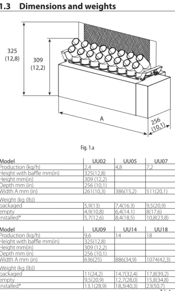
Dimensions and weights
Opening the packaging
Material supplied
Preparing for assembly
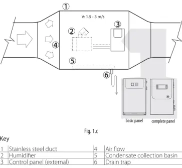
Make sure the supporting surface can support the weight of the unit. The humidifier can only be activated (atomized water production) when the air handling unit fan is running. NEVER start atomized water production without air flow in the duct: this may damage one or more parts of the device.
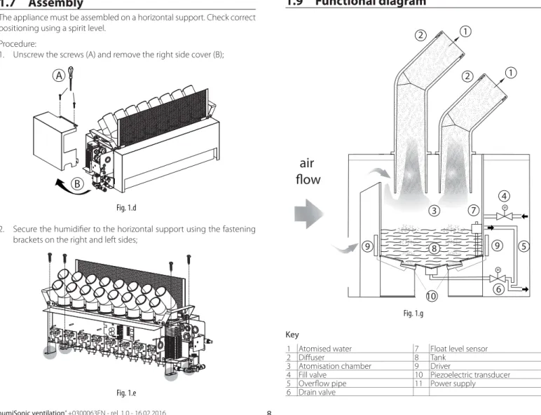
Assembly
Identifi cation label
Functional diagram
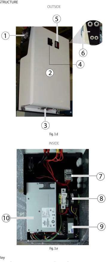
The picture shows the body of the humidifier, after removing the side panels and the cover (see the chapter "Replacement parts and maintenance"). 1 Lifting handle 9 Cable bulb bracket 2 Rear user 10 Piezoelectric transducer 3 Front diff user 11 Electronic control board.
Operating principle
Accessories
Structure
WATER CONNECTIONS 10
- Water connections (parts not included)
- Positioning
- Water connections
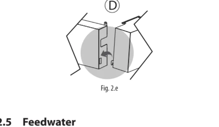
- Feedwater
- Drain water
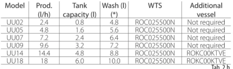
To avoid oversizing the reverse osmosis system, it is recommended to avoid sizing the system based on instantaneous flow rate. 0.a If no storage container is available, the reverse osmosis system must guarantee the immediate flow rate of the fill SV, equal to 2 l/min. The Carel product range includes a series of reverse osmosis systems (“WTS Compact”) designed to produce water according to the feed water specifications and to optimize connection with and operation with humiSonic (see manuals +0300017 and +0300019).
The basic rule for connection to the humidifier is that the water in the expansion tank must be sufficient to meet the initial fill and, if necessary, the wash cycle, while the WTS production time must cover the humiSonic production demand and ship as quickly as possible. The duration and frequency of the wash cycles are parameters that can be set by the user and have a significant influence on the sizing of the WTS system.
ELECTRICAL CONNECTIONS 12
- Functional wiring diagram
- Electrical connections to the “Slave” panel
- Connection cable sizing
- Electrical connect. to the “Master” panel
- Control types
Note: for UQ18B% dimensions refer to the quotations given in section 3.5 regarding "Master" control panel. See figure for minimum clearances in mm (in) that ensure adequate air flow and change inside the electrical panel. This can be connected to a switch, a hygrostat or a controller (voltage-free switch, max 5 Vdc open, max 7 mA closed).
This configuration allows a maximum of 256 devices to be connected with cables in separate channels from the power cable. The table below shows the dimensioning of the 48 Vdc connection cable between the humidifier and the "Slave" or "Master" electrical panel. Depending on the type of signal, atomized water production can be activated and/or controlled in different ways.
Connect terminals COM, +V and M_PB (main probe) to a humidity probe and terminals COM, +V and L_PB (limit probe) to an active humidity probe;.
STARTING AND USER INTERFACE (“SLA VE” PANEL) 20
Shutdown / Standby
Autotest
Signal lights on the “Slave” panel
Disabling
Reset tank hour counter
Automatic washing
Washing due to inactivity
USER INTERFACE (“MASTER” PANEL) 21
- Keypad
- Display
- Programming mode
- Setting/displaying the user parameters
- Setting the Service parameters
- Quick access menus
Access varies by level: User (accessible without a password), Service (password=PW1) and Manufacturer (password = PW2). The display can include up to 50 alarms with progressive numbering, time and date of activation. Press Enter to set the starting hours and minutes of the zone and the status: OFF, ON, ON+SET (ON+SET if probe control is selected).
If ON, the setpoint selected in screen B is displayed, if ON+Set, set the desired setpoint; Access control (GEC): Interval to enter a new service password during browsing, enable quick menu (on/off and set point), enter user password (PW0), change service password (PW1). Procedure: The setting/viewing procedure is similar to that for the user parameters, but the password PW1 must be entered to access the G category parameters.
Quick access menus can be used to quickly access unit information and settings. In this screen, the control set point for the humidity / temperature probe and the limit humidity probe set point can be set.

COMMISSIONING (“MASTER” PANEL) 24
- Scheduler
- Regulation type
- Shutdown / Standby
- Autotest
- Reset tank hour counter
- Automatic washing
- Manual procedures
- Probe calibration
- Access management
- Settings
- Network settings
When the control type is selected, the probes can be calibrated by setting the offset. You can set the delay after which the service password (PW1) is requested, and disable quick access (Quick menu) to the parameters via the Set point and On/Off icons (see chapter "User interface"). In addition, a new password can be set and the PW0 master password can be enabled to access any screen in the programming menu, not just the service parameters.
This is useful in case of frequent starts/stops, to minimize the time required to reach steady operation. Drain valve in standby Open Open Closed - Drain delay in standby 0 min 60 min. The RS485 serial card (accessory) must be installed on the control board in the "Master" panel.
Network parameters must be set in the case of connection to a serial network. All controllers in the network must be configured with the same protocol and communication speed parameters. If you enable serial control, you can set the humidifier parameter via serial connection.
FUNCTIONS (“MASTER” PANEL) 26
- Set point
- Regulation (control)
- Probe alarms
- Flow-rate modulation
- Washing
- Timings
As in the previous case with the boundary humidity probe, normally installed downstream of the drop separator. The atomized water flow rate can be modulated as a percentage from 10% to 100% of the rated capacity. 10% - 50%: one transducer line is always off, the other modulates as described in the previous paragraph to generate the required output (eg 25% demand: one transducer line is always off, the other modulates to 50% ).
If the water filling cycle occurs during the production of atomized water, see paragraph “Refill Tmax”. If sensor activation is not detected within the time set by parameter "Tmax drain" (default 60 s), the humidifier keeps the drain on. Tmax prod: maximum atomizing water production time (drivers active), during which the level sensor must signal a low water level.
The humidifier checks the water level in the tank during the production of atomized water. Tmin prod: minimum atomized water production time (driver active) during which the low level sensor must not be activated. 7.n Refill time: time the fill solenoid valve is kept open, after the control level (intermediate) has been reached during the production of atomized water.
Refill Tmax: Maximum time the drivers remain active during a water refill cycle, after the level sensor has measured the low water level during atomizing water production. During refilling when the unit is in operation, i.e. after the low level has dropped due to atomized water consumption resulting in activation of the filling solenoid valve, if the level has not been restored before the. If, on the other hand, the level is correctly restored within the “Tmax refill”.

PARAMETERS T ABLE (“MASTER” ELECTR. PANEL) 30
Troubleshooting
Note: If the identified problem cannot be solved using the following instructions, please contact CAREL technical service. Power supply Low power supply voltage Check the voltage at the output terminals of the power supply. Dust and foreign objects collected in the tank (*) Visually check the inside of the tank Clean the inside of the tank and replace the transducers Scale formation on the surface of the piezoelectric transducers.
If the cause was not identified with the previous checks, there may be faulty components. Feed water system Float level sensor error Empty the tank, remove the electronic board and check continuity of the level sensor. Water level overflow Float level sensor blocked If the water level in the tank reaches the overflow pipe, remove the connector from the control board and check continuity of the level sensor.
MAINTENANCE AND SPARE PARTS 35
- Mechanical components
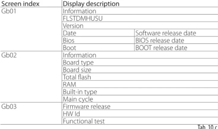
- System information
- Maintenance
- Maintenance operations
- Maintenance intervals
- Replacing the components
- Cleaning the tank
This screen shows the currently installed software revision, memory usage, and cycle time. The fill valve is normally closed and the drain valve is normally open, so when the humidifier is turned off, the unit will automatically drain. An operating hour counter (actual production) and a unit operating hour counter (total hours) can be set, together with a maintenance hour counter after which a warning message appears on the display.
Note: special maintenance and repairs are recommended to be carried out at least once a year, regardless of the number of operating hours shown on the operating hours counter. Once the cover is removed, simply lift them up to replace the difficers. It should be replaced after about 10,000 operating hours (depending on water quality), even if the unit can continue to operate while the actual capacity still meets the requirements.
The converter must have the marks placed in the same manner as the adjacent ones. Note: the torque of the nuts securing the transducer must be 4±0.5 kg cm. Important: if the transducer is mounted rotated 180°; incorrect assembly will cause a reduction in production of atomized water and possible malfunction of humidifier.
Proceed as shown previously to remove the side panels and top cover with the various users.
GENERAL FEATURES AND MODELS 38
Cable cross-section
Technical specifi cations
To optimize the control and management of multiple humidifiers within the same behavior, it is possible to connect them in series according to the diagrams reported below. The control signals (probes / humidistat / external regulator) are only read and handled by the Master who will then adjust the operation of the slave.
Fuse table
MULTI-UNITS INSTALLA TION 39
Connection multi-master (until 4 masters)
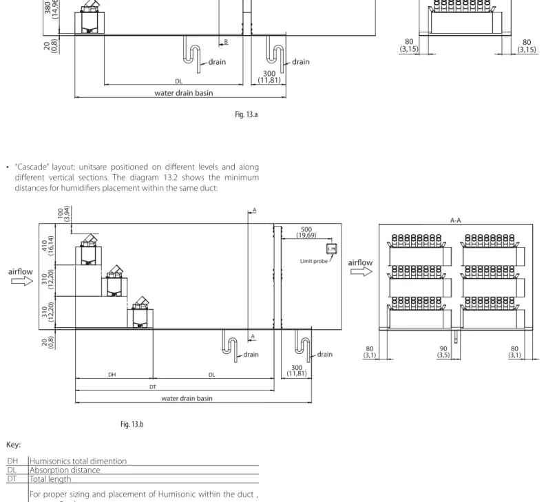
When the units to be installed in the same channel are in high number (5 to 24 units), it is appropriate to follow the diagram in Fig. If several Humisonics are to be installed in the same channel, it is necessary to arrange them. inside the channel to obtain a homogeneous and constant atomization. Online” layout: units are placed at different levels along the same vertical section.