----
® HIGHLEAD '
GC188-M-D
(WjJ!~-fJL
ftffllJitm~.
~14l¥* ..
~ ~ - I ~ m ~ ~ r
SHANGHAI HUIGONG N0.3 SEWING MACHINE FACTORY
I
'Z:C"i~. ·z:c:tU~Hi ~~fljj SAFETY OPERATION INSTRUCTION
1-;T
f2.~ ~f:ilHs Lft,
{I'fr.:~-i. iftlir\tJl~ntr, .!.'xi111'T1£f*~ffllf'i:. ~f~~Lftz 1W,
ilfiAti-I~J~~fflhl~~o ~~~M~fflhl~~~~. ~~~~A~$Mo 'j;
T
12.~ f{)}JQ1iH?ffJl
~ J~1111
MEl'~ ~?f.tJJ; in, t1,{1iil: f,[n T
i~ n)] oIn order to operate machine safety, please read the INSTRUCITON MANUAL carefully before installing, operating machine or exchanging parts and making maintenance. If not, it will cause personal injuries.
To make you kown well, explain the machine's warning marks as follows:
~l:f-t~:u) l="-1 I \ / \ ~?f.r*J ~ t~?f.tffiR
fff
i,Ri*J ;g
warning Figure Meaning warning Mark Meaning
A
Mrw~ng CAUl ON parts may r_.ause ~.1J g:p f:r ' if
~J) _[ft 1J t£ m 7r. JE flfil ntr
~JJ rtJ
Motion section, Be cautious
~
Showing right rotation&. ~'~ '"" ·-·~ "")
of injuries direction~~~8n~l,ec creanH".g etc
WARNING MARK OF SAFETY DEVICE
1.
1-; trW
JU7~ 'Z:C:'f'::?~i"i:R~J~~X
rl'Ti ill:flY:rJ'J<i~~~lt{t:'V:;i&-MwdtM, irHJiliA
$2~~i':c
f,[rJ8('&~-- it't~'te~flL tt~U!'l~1:t&.
i:f
!~JtH~l--.
-=Hi~2i
ifliffJ'fr.:~tr:Kt~GZtl::!Lt.
~ Ffr-1-~Eill1'TMHto 2.'h nJJ Jr. A
~IJ8£, tE ~ ~#]'f[W: t1fTn1% fr.
irr~Jt t':k
~ ~fif:. :ff 5ff!i)_JtOJ
~:J ~J'!J'fr.:
~[i:J]t?s'~ficm,
Jf~lJt~di'fJL~o3. 'hTm~A~~M. m~t~~M~~~~m. ~~~Wfflm~~~c
l. In order to avoid the accident occuring which caused by the deficits of safety device. before operation, make sure the safety device at itis right position. for example the belt, the finger guard and the safety plate.
2. Before operation, make sure the removed safety device has been installed wen and ascertain itis effects.
3. Keep the warning marks clean and clear.
• I
--- m~*~~~ - - - -
1. H~Jti llt~i'3HJLst,
£,;giJ1i'TtJJ?;SirrrrYJ El
0'~ :!£:zts:~~tiHffio, 2.
{'Effl I>~~tjJtJlz -fW,
if11~li#:;t,:fifJTI i5?,A] ts:fr
fAJr'BJiff:;fH§'lf:; X f-t,
[fi]Rt fl¥5- lltfrr:ffJ i5?,AJj
=j~~-~1*n;.
U~~t~il.iHSti"'il~o3. llt~~mB~~oom~~~~~~-g~mo
4. f:'l':mllt~f>JJVltP~i'3JtJLZ9Jf'f:41• fifTifB'~~~set~a~~¥~~/EBitl:li:o &1f~~~!EB'~~~~
'ff(.Y~~g,JJ m~
Jl-_ f:'l':Jti
o5.
llt~fjjffiflEB
~~:i]:±ii;i)l\i'f~i*ftAD'L*f*f'f:o
6. 11':m~t3JffiS;f, ~i)(Jt~~~JJ!P~lH~o
7.
~Z:'±T1H¥f/£8J, fl&Ht:k!lj.l:~;t~ff:k, ~W:Fft!WJi~tw~o7- HJlrr,
~'rr, 5t~ ~~3{-tJt fP1EJ~Jt'E~Bt a7-29!~TFLt't.
HdJ!;P, ft-t&.
~'ft. 7t~~-:i!:ftl:t.
!Pft~. st~. f!J-'i'f~~~Bto 7-3 fi;ti~BL
7-4
I ft ±m Jiff kAT !:'x
~ff _ _[ fn:Jj Jiff B;f
a7 -sff
m
~ir
~.1tst.
i¥f~ffl'P;Jb5c
~~1LZ.€ -JI}:lttfr
o8.
UHJL U 2Utt
~ ~it{'f mEt~tJUtl3. i1fJ
iff~§'~~ i*tfiiA~FH¥f ~ ~~¥1J Hz ltt.t at,
~xAJ.hJH'XBt,0ZJL
~ll?¥f
lJt ff :k
flil1)} jt·.* E& ll3t il5 fT
0I
9.ft
ll:J{jc:r- ~ HHJ 7fT~ tJHJL Jf:k:® ~ m '4=# ~*=ito
I ; o f'i
*:~tJHJLm fttJ~.c9::iTI.
;m~0 E8
~:ct~!'liJII~m:tR* A.Bt~x~***fr oI
II. -· J11Z(t~?:if fl:ti* TI'fl Eh 5Z:iliJII
fJJ;B'~ A~*:i!Hr
o1 12.
1J
X~!!JJfJlErJ
~ ~1JITUO'J{i;tlW:.i1f:_fi;tJii: E8
~'&'H~B'~ Jt~tt* AM.~~*Fi'.l ~~~tPt§'* F Jltfr
a13. ~JfJL
i5f
?f1Y.:k2:~. 0\ffir 1}
iidfa2~EB~ftst,0Z
-t:JJiiff2~HdR3Vl fjt~lf,J§"-JI}Jltff
o~-
'JJr
tUf,·,tz "]\. i~H, F~C!.C':\t:Jmt-1>
lrf]ll;t 0Z :rt ::f~ r.'li ~Uc'f'Ntffl ~:55iUM
F}i1Ur5P(ri]Enltli r:: f.tm
a1 16.
rt M:tffi }d0Jtl
~t.f rt
/c{ 4i !' Hu
i~B'J
A*~ ~L ~iW- trii *
·.12:'Jvi
.8J~iu
~±!PJ ru ffiLL
'---·---~-
1. 1:7Tfl1JJJ::.tz:j:_fH!R~$m. ~:f~rrH7t~mi'fJ;tki$r. tr7t~9:.~itr.&FM!m
~
9:. f§ r*J EfJ 4= 14
01. 1:7Tfl1Jll::.A~$M:i'fJ£j:_, ~:f~if~r~Wfl1J~-- ¥mfl1J~H~~~~
i': i'fJ :tk :$ r
~ w~g,JHJl o
2.
:i:JT fl1J
11::. :f&:'ffA,fJlHI'fJA~$i!it, ~g,JJm~w~~/F~~-f-m.!k:tt.
::&~R -~~w~. v%~W. ~~. ili:f~re*®M~mHkOOo3. 1:7 Tfl1J
ll::.A~$M:I¥J£j:_, tr7f~mtat l;J_&~g,JJf}l~~~, ~:f~re¥tr1it~HJl
ft i'fJ ffl ili: o
4.
1:7 T
~JJ JtA~$M:i'fJ£j:_, ~t~JJtfl~~~~:f~re¥tr7l~~tl~tttff7~-r*Jos.
H~m•~~. ~~~m~~~o:i:7Tfl1Jll::.¥~~m~. ~~~~~n:f~re¥•:i!I~~o
6. jg
T fl1J ll::.A
~$M:i¥J£j:_, 7l~ff'J~g,JJf}l~:]S@JJJiU-!Effii':Bt.
Jiii~:f~~tt¥o
7.
1J T ll7J
11:-_ *~i'fJ~ilJ:@:bX:A5t$M:. n~ff!J~g,])f}lBt. ~iEP~w-fPV%~WBt,
m---J:E:*=Mftmlo
8. ~ffl
f§J
~Rl!;~Bt, ~~JJfJl ~ l1::.1!;~7CF"if
o:1;; T fl1J
ll::.~:>'~i'fJ~ilJ:@:IJX:A5t$i!IX.
~ii~:f~75i2:kftmo9. 1:7Tfl1Jll::.FM!Et!.$M:.
~rftmt~tti'fJ;tk?$, ~:f~~~~g,JJfflo10.
:1;; T fl1J JtfM!Et!.
fPrn±t~9:.4=flf:,tttftmi'fJflll!J:Bt,
~7t:kM,fJlHftmt7f:ko. Ill•
IMPORTANT SAFETY INSTRUCTIONS---
Puttmg sewing systems into operation is prohibited until it has been ascertained that the sewing systems in which these sewing mach1nes will be bu1lt into, have conformed with the safety regulations in your county
Technical serv1ce for those sew1ng systems is also prohibited
1 Observe the bas1c safety measures. Including, but not lim1ted to the following ones, whenever you use the machine.
2 Read all the instructions, includmg, but not !1m1ted to this Instruction Manual before ycu use the machine. In addition, keep this Instruction Manual so that you may read 1! at anyt,me when necessary
3 Use the mach me after 1t has been ascertained that it conforms with safety rules/standards val1d m your country 4 All safety devices must be in pos;l!on when thP rnachme is ready for work or in operation The operast;on w1thout the
spec1f1ed safety dev;ces is not allowed
5 Th1s machine shall be operated by appropri13tely-tramed operators.
6 For your personal protection, we recommend that you wear safety glasses.
7 For the following. turn off the power sw;tch or disconnect the power plug of the m'lch1ne from the receptacle 7-1 For threading needle(s), looper. spreader etc. and replacing bobbin.
7 2 For replac1ng pnrt!s) of needle. presser font throCJt plate looper, spreader, feed dog needle guard. folder cloth guide etc
7-3 For repair work
7-4 When lea·o;ng the working place or wr1en \he working place IS unattended.
7-5 When us;ng clutch motors w1thout applying brake. it has to be wa;ted until the motor stopped totally
8 !f you should allow 011. grease, etc. use with the machine and devices to come in contact with your eyes or skm or swallow any of such l;qu;d by mistake. 1mmed1ately wash the contacted areas and consult a med;cal doctor.
Tamper1ng w;th the l;ve parts ana dev1ces, regardless of whether the machine is powered. is proh1b1ted
Repair remodel;ng and ad;ustment works must only be done by appropriately trained technic;ans or spec;ally skilled personnel Only spare parts designated by JLJKican be used for repairs.
11 General ma;ntenance and mspection works have to be done by appropriately tra1ned personnel
12 Repa,r and mamtenance works of electr~cal components shall be conducted by qualified electric technic,ans or unde the audit and guidance of specially skilled personnel
In
Whe11e•;er yot; f1nd a failure of any of electr~ca' components. 1mmed1ately stop the mach;neBefore making rep;cm and mallltenance works on the mach me equ;pped with pneumatiC parts such as an air cylinder the a;; con1pressor has to be detached from the machine and the compressed a;r supply has to be cut off
Ex1stmg res1dual a;r pressure after d1sconnect1ng the a;r compressor from the machine has to be expelled Except1ons to th1s are only adJliStments and oerfon1ance checks done by appropriately trained technicians or spe-
L
cinily skilled personnel14 Per~od;cally clean tile mach111e throughout tne period of use - - - -
15 Ground;ng tile n'acllllle IS always necessary for the normal operat;on of the mach111e The macll111e llas to be operated 111 an env,ror:ment tllat IS free from strong no1se sources such as h1gh frequency welder
An appropr~ate power plug has tr' be attacherl 1r' tlw mach1ne by electr~c techr:1c1an.;; Power pluq has to be connected to a grounded receptacle
- - - - - - '
17 The mach1ne IS only allovved to be used for the purpose llltellded Other used are not ill lowed
18. Remodel or mod;fy the mach111e 111 accordance w1th the safety rules/standards while tak;ng all the effect1ve safety measures.
L
Fa!!Shi Co Ltd assun1es to responstbtltty for darnage caused by renrodeltng or modtftcat1on of the mach:ne1
19 Warn1ng h111ts CJre marked w1tr1 the two shown symbols
Danger of InJury to operator or service staff
Items requ1ring speCial attent1on
FOR SAFE OPERATION
B
1 To avoid electrical shock hazards, neither open the cover of the electrical box for the motor nor touch the components mounted inside the electrical box.1 To avoid personal inJury. never operate the machine with any of the belt cover, finger guard or safety devices removed
A
2. To prevent possible personal inJuries caused by being caught in the machine, keep your tingers, head and clothes away from the handwheel, V belt and the motor while the machine is operation In addition. place nothing around them.3. To avo1d personal inJury, never put your hand under the needle when you turn "ON" the power switch or operate the machine
4 To avoid personalmjury. never put your fingers into the thread take-CJp cover while the machine 1s 1n operat1on
5. The hook rotates at a high speed while the machine is in operation, To prevent poss1ble inJury to hands. be sure to keep your hands away from the vicinity of the hook during operation. In add1t1on be sure to turn OFF the power to the machine when replacing the bobbin.
6. To avo1d poss1b!e persona! inJunes, be careful not to allow your fingers 1n the machine when I
tilmg/ralsmg the machine head
I
7 To avo1d possible accidents because of abrupt start of the machine, turn OFF the power to the machine when tilting the machine head or removing the belt cover and the V belt.
8 If your machine is equipped with a servo-motor. the motor does not produce noise while the machine IS at rest. To avoid possible accidents due to abrupt start of the machine, be sure to turn OFF the power to the machine
9 To avo1d electr1cal stwck hazards. never operate the sewmg mach me w1th the ground w1re for the power supply removed
10 To prevent possible accidents because of electric shock or damaged electncal components(s) turn OFF the power switch in prior to the connection/disconnection of the power plug
. v •
From the library of: Superior Sewing Machine & Supply LLC
§ ~
Contents
Operation Manual · · · ·· · · .. · .. · .. · .. · .. · .. · .. · .. · .. · .. · .. · .. · .. · .. · 1
'2J:{Lf:tf*
Parts Book .. · .. · .. · .. · .. · .. · .. · .. · .. · .. · .. · .. · .. · .. · .. · .. · .. · .. · .. · .. · .. · .. · .. · .. · .. · .. · .. · .. · .. · .. · .. · .. · .. · .. · 25 GC 188-M-D~(r:j:l
JJN
ffl)Model GC 188-M-D (For Medium Heavy Materials) ... 26
L tJl)t)till
{4Arm Bed components ... 26 2. _t~. M~rt:7t~fi
ft
Main Shaft & Thread Take-up Components ... · ... · .. · ... · ... 28 3.
rrff.
~rt:
71-~11f-t
Needle Bar & Thread Tension Components ... 30 4.
fff-4.
f'~rt:5Hfif't
Presser & Tension Release Bar Components ... · ... · .. · ... · ... · 32
s . 1:J rt; 5Hll 14
Hook Priving Shaft Components ... · .. · .. · .. · .. · .. · ... · ... · ... 34
6.
J!H5Hll ft
Feed Mechanism Cornponents .. · ... · ... · ... · ... · · · · .. · · .. · ... · .. · ... · ... · 36 7. illH~li-71-tllfl
Feed Regulating Components ... · · ... · ... · .... · ... · .. · 38
s .
lj'Jrt; 7HJH4
Thread Trimmer Components · .... · .. · .. · .. · .. · .. · .. · .. · · .... · .. · .. · .. · · .... · .. · .. · .. · · .... · .. · .. · .. · .. · .. · 40 9 .
t£: rt; 57'- ffi f't
Wiper Components .. · · ... · .. · ... · ... · .. · ... · ... · ... · .... · ... · .. · .. · ... · 42 10. il-~¥ff 5HtH~
Lubrication Components .. · · .. · .... · ... · .. · .. · · .... · · .... · · .... · .. · · .. · .. · .... · .. · · .... · · .... · · .. · .. ·.. 44
lL i'ltlftt.
~ttlffW-117ttllfiOil Reservoir & Knee Lifter Components ... 46 12.
tJL *
~ttf!f:c 1)Machine Head Accessories( 1) .. · .. · · .... · .. · .. · .. · .. · .. · · .... · .. · .. · .. · .. · .. · .. · · .... · · .... · .. · .. · · .... · 48
tJL 1JfH't(2)
Machine Head Accessories(2) ... ··· ... 50 13.
tJL
~.f1 f&. rtr
~ 1,)-f!Ht
Machine Stand. Tabk & Electric Appliance Components ... ··· · · ··· ... 52
fF $%I l'fJ 51~ ~:rw:
BEFORE OPERATION
~ ~
&~'--- IX J&, A 7 ~JJ JttJH~~l~i~tdf11=~t~1JJ, iw Ml i)Jm l' r_m §I
0A CAUTION:
To avoid malfunction and damage of the machine, confirm the following 1_ iffi~
r*J
*:!Joiffi~::ftiUf:$2-
fil~±E~Si,
J-l-__t*'f::91'ffiiJlH~loJ B 7J
~SiH1:J loL
i!~,::f
titfilJ$~3_
tt~-~$, ::f~mffl*R~~~Mfll~~~4
~~~Mfll~~__t_M~~lli&ffim~~~~1 _
Never operate the machine unless its oil pan has been filled with oil.
2. After setting up the machine, check the direction of motor rotation. To check it, turn the handwheel by hand to bring the needle down. and turn the power switch ON while observing the handwheel. (The handwheel should turn counterclockwise as observed from the handwheel side.)
3. Do not use a larger motor pulley for the first one month.
4 Conf1rm that the voltage and phase (single or 3-phase) are correct by checking them against the ratings shown on the motor nameplate.
1~ffl 7i~$IYY:
OPERATION PRECAUTIONS
..
~&~,---1
~~~~--I A T~JJJt~ji--~~M@PX:~$~. iw * t* ~1m f6 {!} ill1:r
c8 WARNING:
Turn OFF the power before startrng the work so as to prevent accrednts caused by abrupt start of the sewing machrne1 m~~~H*~fil~±E~s-1. ~~~~$~H~~M
2 tll~±E~Si, ~~ 1~-'¥ :t§1$A~t~:fft.PS!
r*J
3. fil~gM&m=m~~s-1. -~~m~~fil**
4
~~~~Hm~s-1. ~~m~~~5
tll~~$~WHBJ. i!~::fft ilifiilJ
A.~~~~~.:J.,0HE16J3t~~ili:__t$-t;·-v··
H~~~. m~$'t:f!J ~MtJl
6
~m~~~. M~~. ~~M~~~~~s-1- ~~HMfil~1 ::f~m~~*~~~~n~m~M~*oo
8. ~AA~~fll~~~~. ~~. ~~. ~B~WI~
1.
Keep your hands away from the needle when you turn the power switch ON or while the machine is operating.
2.
Do not put your fingers into the thread take-up cover while the machine is operating.
3. Be sure to turn the power switch OFF before tilting the machine head or removing the V belt.
4. When an operator leaves form the machine. mack sure to turn off the power.
5. During operation, be careful not to allow your or any other person's head or hands to come close to the handwheel. V belt. bobbin winder or motor. Also, do not place anything close to them. Doing so may be dangerous.
6 If your machine is provided with a belt cover, finger guard or any other protectors, do not operate your machine with any of them removed.
7. Don't clean the face of machine head with thinner.
8 Penrlically clear dust and lint from the machine, and do the maintenance work
1.
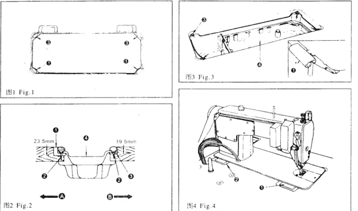
;f:Jl~~~~(f!j1 ~ ~2~ ~3~ ~4)1. INSTALLATION (Fig.1, Fig.2, Fig.3, Fig.4)
* 5Eil:&~~:
1 ) XIJ 1l B: tlm R I f'F fl
[li]ilt
8'~ [liJ1M
a2) ~n
Li-1 ffr ;r, , i-1t
~LRXlJ 1l :7.: NKD JiHEh fnt
[~H C£l Rtl 1£ 1r
A -~.iti C
~JmHt: :%';-~ jti),¥.t M" .R XlJ ft ffiHf':@
m NJ t-t 2-Hr C£l IQJ 5E tr: s - -:ill Ofl +JL :J-;- ii tt
r£Jt§< g. --
jti)..ttl f8· re
X~J:m: ® nz tr: J.Lto coo
1 ,oo
2) 3)?J tJL -'k
iit:tc~CD!JiAm; f& fL I7'J,
'=JiJ
,f&(J~Jtfl-*
iiffl~ffi(£}-f@ itt g., ¥}¥-f tfl :J.; 1iJ¥'1 R1l f!. ftJ 81 tJl
iJ,HH~@_L (003, ~4)
" Installing the oil pan
1) The oil pan should rest on the four corners of the machine table groove.
2) Fix two rubber seate CD on side A (operator's side) using
nails~as illustrated above. Fix two cushion seats ®on side B (hinged side) using
nails~-Then place oil pan @on the fixed seats.
(Fig.l, Fig.2)
3) Fit hinge CD into the opening in the machine bed, and fit the machine head to table rubber
hinge~before placing the machine head on cushions® on the four corners. (Fig.3, Fig.4)
. ) .0
,\~
llll Fig.l
[f]2 Fig.2
--~ C1
1 ).
ll@ '
0 I
rm
Fig.3~
' '[tj4 Fig.4
.
').
1.
m~Et-Jii!Ji~(oos,006)
1. LUBRICATION (Fig.5, Fig.6)
1
i1IJ
?i!H~ ~: ( 00
5)*
7f$M:
1)
rtJ lEB fttCD 1*J
1JD~f~Jffl)IB(l
015-8 irtl)
¥HIGHic-'%tfll
f_ll:Ao ( ~5) 2) '~)rtJ
ITiJ f~-TLOWi~5B.fl-fl}hUtalo
3 l !Jo ;m 16, -Tfi9J :fll
~.GZ
:~-:fu ?1±J
~-\S ~ruta1 w Cl!
_t.i5t
BJH~fll'fl .iE
-~~ o-+
l Zf: f
~i~ffJ?rtl it
~H/'-tJ
,t2,J~fll1hrtlit g;
~,!C::ko
* il~:
f~
ffl m tJl
~9.t
::g--t~JiJJ* fi ffl i181 tll
~a1, B tt
&7H~ 3000- 3500H81 :JX
~l' fifll
~li!1f -t-
:5ti~~tli¥l:@B'ti:iE~, 2 . 1m]
iJ mJ
fi~iffi
~: (
006)1 l ~UJJidlliifliliJ
MCD.
~lJU
iJ,'iJP" Jjttx illJ MCl!Ef-JffJjffi il:o
2) i-llliitWliJ
t~-'W.JB}J rtJ
~z;i). ~~L8Allill
Jjtt~illJ
j:j;l:j B•j,im
il:~ilji&
1j\Ulo
3)
illl
!:iflil1H~ ~JJCJJrtJ
~~:;iJ. ~~L8AcJf'fr'*WE~Bil
j:j;l:]Bt,?!Eil::il5¥H&k fflo
3 1m]
::p
mEt~iffi
~:( 00
6)1 J
·JJf F: IWl rliJ
~ -~ _t 8~i!E J:
ifW¥I ~~H ®
~JJ+
JT ~J A$~4iJ
Ut, iUl it
;j4t J~A
a2) ~S ilB
M:
ifWiJ-P,.~H®-'M-/i
itJB~iJJHJ,i!ll
~;j4fi!£;J\o Information on lubrication (Fig.5), Before starting the machine
1) Fill oil pan
CD
with sewing machine oil ( l 0 white oil) up to HIGH mark A.2) When the oil level lowers below LOW mark B, refill the oil pan with the specified oil.
3) When you operate the machine after lubrication, you will see splashing oil through oil sight window (J) if the lubrication is adequate.
4) Note that the amount of the splashing oil is unrelated to the amount of the lubricating oil.
~ Precaution
When you first operate your machine after set up or after an extended period of disuse, run your machine at 3,000 s.p.m. To 3,5000 s.p.m for about 10 minutes for the purpose of break-in.
2. Adjusting the amount of oil supplied to the face plate parts (Fig.6)
1) Adjust the amount of oil supplied to the thread take-up and needle bar crank (J) by turning adjust pinQ)_
2) The minimum amount of oil is reached when marker dot A is brought close to needle bar crank
ClJ
by turning the adjust pin in direction B.
3) The maximum amount of oil is reached when marker dot A is brought to the position just opposite from the needle bar crank by turning the adjust pin in direction C.
3. Adjusting the amount of oil supplied to the the hook (Fig.6)
1) More oil is supplied as oil amount adjust screw® mounted on the hook driving shaft is turned toward+ (in direction A).
2) As the oil amount adjust screw @is turned toward- (in direction B), the amount of oil supplied will be decreased.
. l .
, I ~
~5 Fig.5
3. :fllltl¥1*it(!!J7)
3. ATTACHING THE.NEEDLE (Fig.7)
" ti
~tfl H WJ, &<uHJJ 151
~ z:,-+1tn
~ iP¥ti;lftHH-t-
7-JDB X 1"1H),
'r}, ttHit~ftl!Hl :1:r1'·J {flfHl fu
~i;ff3!E::i21fijEi3 C-tltfl ft
o1) ~iJJJJ't{~hH r ijfrJNo:r\;~
2) Nitt
3tftt~HaJ,
H~f!L
HCfJ8~I
11HIC ffll5t A.i.Ex·J t.1 Jifr,JB"
3) ~tJLl'rWJrifi:Y~1ni,JM~
A
o~r{l({jil. rL~f':tJi~~jJ11Jll:.o
4) NE~
:tl'i
5\.~HaJ,5)
fi£·f:1::tJL
ft(Y,J l(f,~'CJ] /r}r!r,JDu*
Turn the motor power OFF before starting to attach the needle.A needle of DB X 1 '14 should he used. Select a proper needle size according to the count of thread and the type of material used.
1) Tum the hand wheel until the needle bar reaches the highest point of its stroke.
2) Loosen screw
aJ,
and hold needleCD
with its indented part A facing exactly to the right in direction B.3) Insert the needle in the direction of the arrow until it will go no further.
4) Securely tighten screw
W
5) Check that long groove C of the needle is facing exactly to the left in direction D.
lt17 Fig 7
. 4.
4. ~'L'fn~i!(I!J8)
4. SETTING THE BOBBIN INTO THE BOBBIN CASE (Fig.8)
I) *1H~
(,
:J%-f&'L'~Af~-f~*Jo2)
1ett.MJ~f
J:.8'~~f-WArp#jJ:, !MB1J
(l'J:tL tU
oi!:ff. gx:@i1*fX'i:T
JAttJLB~'7 I Il-l
o3) j,'fi((fj(CUJ, f~ ,c_,J~ t't<~~*
1J
~J f!;idJoI) Hold the bobbin in a way that the thread open end is directed to the left as observed from you, and set the bobbin into the bobbin obbin case.
2) Pass the thread through thread slit A, and pull the thread in direction B. BY so doing, the thread will pass under the tension spring and come out from notch B.
3) Check that the bobbin rotates in the direction of the arrow when thread C is pulled.
l!fl8 Fig.8
I s. 1m~a15.Fit(009) ]
~~--5_.T __ H_R_E_A_D_I_N_G_T_H_E_M_A_C_H __ I_N_E_H_E_A_D_(~F~ig~.9_) ________________ __
I -
~
II
1119 Fig.9
. .
6. lt Jf!?:tf.JiFcJ
~( 00 1 0)
6. ADJUSTING THE STITCH LENGTH (Fig.1 0)
1)
~ill fl.~§::fjj'HHCD?JJ M
:Y~IT rtJ tb9J,
iitE3~?Jri¥fi ~ ' jx.J
l#~-fJl7Cs~8'0 ~~Jl~A"2)
Jt'HILL
(Y.J ~rj]JOlC¥m 1t% :tUJ; ,,
3
> '11
f!s:~J.t1(iHHbll: K: 13! BJ, 11::
{'frJjh:'fHN.lC~)t:VJ (ifj J-~ )Jrt,J1Eft0
[r1]n.J,
~jiJJizH4R§:MHllo1) Tum stitch lenght dial
C1
in the direction of the arrow, and align the desired number to marker dot A on the machine arm.2) The dial calibration is in milluneter~.
3) When you want to decre:1se the stitch length. tum stitch length dial
CD
while pressing feed lever~in the direction of the arrO\v.
v
I
1'810 Fig.l 0
7.
*~~(0011)7. THREAD TENSION (Fig.11)
1 . ®
~stt:1J 81 ifcl 1J:
1) *H J-
1'~~.9;.~I'J:CD ?JJiifo!HJ H
JJ JI,J ( UilA)fJwJ) tU
zJJ f!J,Mtl:C, \iiH'±: tl fL £tt\!:8'0
-KOC~Jt~m.lltc 2)'f:'i•WJ&nHi Jnf,J
c~llB J;(<,J)Hz9JilJ,
vlutU:jZ,KJJ~o3) f1:;f.(; >}(ftP,.~
t:Jell4iJJ
i1[0!fi.fHh JI,J (
UilCh H>?tt iJJfiJ, rfutl.t
~Ktr+itlrl A:,.
4)
:fi'?JJ&nJri-:trri,J
(l!PD}Jrt,nttz9Jfl·L rfilfl.dK
JJ~-;;~,t;J,o2
Iff
~stt :1J 81 ifcl 1J :
I) '{j:t.HY T J.·Jfttt
~K:IJ
if~ i'i<l;.~1 J®•:iJJJifiiUJ.j 1 I h rt,J C
UllEJTf~]) t~4J n-t, lt'sU1dK trf4tf'? :ko
2) ={:}:
E;ijjJ1!
B;JHJT JfiJ
(l![JF};Jr'j) H
tJJilJ,
l((f\: ~K )J:f41P:H\o
1. Adjusting the needle thread tension
I) As you tum thread tension No.I nut
CD
clockwise (in direction@ ),
the thread remaining on the needle after thread trimming will be shorter.2) As you tum nut countnc!o<.:hvise (in direction
@ ),
Lhe Lhread length will be longer.3) As you tum thread tension No.2 nut
ell
clockwise (in direction© ),
the needle thread tension will be increased.4) As you tum nut
ell
countnL·lockwise (in direction© ),
the needle thread tension will be decreased.2. Adjusting the bobbin thread tension
.
().
I) As you tum tension adjust screw® clockwise (in direction®), the bobbin thread tension will be increased.
2) As you tum screw® counterclockwise (in direction®), the bobbin thread tension will be decreased.
l1lll Fig.ll
8.
j:jt~li(1!112)8. THREAD TAKE-UP SPRING (Fig.12)
i&~:Ht~~
l!
81~M;:I) JLfE.jJ_0j£ {i[:IJ\.~
fTWo
2J
~1Uf:IJ\.~H@MJifDlBHt1J!~J C~PAiJrPJ) ~ifJBt, tj[fJJif81tlifJ_~;J-1t±~:Xa 3) 1\::'ktf:IJ\.~Hif:Jli~StHJJrr,J C~PBiJ(riJ) ~ifJBt, tjt~jf81~4Jil;J-1tfPt;J\o2.
22
~:Ht~~ t})815¥:::tJ:
J)
ti1f.f'_0f:E {\f:iJ\.lMJW,
JH~:i;tJ-;idf:IJ\.~tJ@o
2!!W:.f'.0
IE fiLIJ\.~ H@o3! ~ *tx!J\.~
TT®'M!Illf!Ht111J f1iJ Cf.llA/J rPJ)
~ifJHi, tjttl:~A'051\ ::fJ ;J-1t±~:Xo 4!-te
~ tt!J\.~1 T@'i!Jiil! lltH JT
rt,J ( ~PB JT f1iJ)tvzJJot,
Vtttj[(J'~ ~Kh
;J-1ti,t~!J\a1. Changing the stroke of thread take-up springCI.' I) Loosen setscrew
Wo
2) As you tum tension post@ clockwise (in direction A), the stroke of the thread take-up spring will be increased.
3) As you tum the knob counterclockwise (in direction B). the stroke will be decreased.
2 Changing the pressure of thread take-up spring'}'
! ) Loosen setscrew
W,
and remove tension post®o
2) Loosen setscrew @o
3) As you tum tension post® clockwise (in direction A), the pressure will be increased.
4) As you tum the post counterclockwise (in direction B). the pressure will be decreased .
. 7 .
tD
I
[!f] 12 Fig. l 2
9.
ffM!Jt.&~(l!]13)9. HAND LIFTER (Fig.13)
1)
f-} :t:
fl§',:PJ" ffi
l}tpt& f-(l)
~JJA1i
(oJ ~z9J, {~ n~JJtMttf o/.) f!~ 11-lil A,(l f:L>-t(. '{ f~J 'I c "i A{: ~1'- - ..1'.1)4Ji1'.,1n~IL- /'].! ... . ·t_ ·1''-<o
3)
~!£1ltP iN fCDWJB)] rs
Jt'f:QJ
flJ,LEW;ll;f-(f
il~ [r~ J;]Ukf;J.i'!'o
4) xtJJ*W:U~IltPITii §, U~~j!.jl8~J
ff]g ii
~'J'h
101ft ;j<:, J&j( tfltfit~~JJJ
13~*o I) To stop the machine with its presser foot up, turn hand lifterCD
in direction A.2) The presser foot will go up about S.Smm and stop.
3) The presser foot will go back to its original position when hand lifter
CD
is turued down in direction B.4) Using the knee lifter. you can get the standard presser foot lift of about lOmm and a maximum lift ofabout 13mm.
~
. I!
0
1.
~\
//I
[I]!3 Fig.l3. 8 .
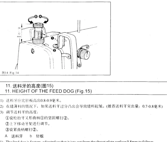
1 0. J±Mil J± 1J ffJ ifc] T.i ( 0014)
10. PRESSER FOOT PRESSURE (Fig.14)
1) )'j;ff',0i)6J n;:!P,.~
£t(l),
II@\rtJ
c~nA:1frPJ)
~i;.IJJl~)jtjliftj"iJ!FJHT'ffj)¥f±fl151lio 2) JJ!rtJ cmlB/J(IlJ)
t~i0JI-:IJ!;jlifi'fl1J't~n, ffjJ~{}Jt~~o3)
;rtl H~1---: ';[;,t!;>3:"'1UJ~-mi!J!D-M\~PJ lJ J1 l fw.: }'j'~ ~OJ :t.J;.'"J~ UJ-~O
4)
x-t
~f&:tflNrm §f. f:E)jtjl~1Y!P,.~HB'0f!Fi{E~f!it:l:729-32~* (50JT)h::ba
1) Loosen nut~. As you turn presser spring regulator
CD
clockwise (in direction A), the presser foot pressure will be increased.2) As you turn the presser spring regulator counterclockwise (in direction B), the pressure will be decreased.
3) After adjustment, tighten nut
Clla
4) For general fabrics, the standard height of the presser spring regulator is 29 to 32 mm (5kg).
ltl14 Fig 14
---~
11.
~;f4~ffj~Ji(lfl15)11. HEIGHT OF THE FEED DOG (Fig.15)
I)
iE H
:1~Ci lt Hf&
rt,i lfJ0.8-0.9~*o2) {-E~iW'Hfl'0'fl11x F,
lzn:W.i!H 5fi15t{1 :U i':
~n~:f:J-gM:acttt#.i!ft:f* t!Hl:
0.7-0.8~*) 3) if~ 1'i i~ :f'~ ~-(1-J 1~-J IJ[:CDhiit~tfl 'if~
x M Rtl
MCDEtJ~~ 't~f:
J~o~
t -r
H~:01 5f
~! ~~tt fril~11·
0®hii
~rttl
M't~HClla A ~:f43f bHt.&
I) The feed dog is factory-adjusted so that it juts out from the throat plate surface 0.8mm to 0.9mm.
2) If the feed dog juts out too muCh, puckering may result when sewing light-weight materials.
(Recommended protrusion: 0.7mm to 0.8mm)
. 9.
3) To adjust the height of the feed dog:
(I )Loosen screw
Ql
of crankCD.
(2)Move the feed bar up or down to make adjustment.
(3)Securely tighten screw(£;
a Feed dog b Throat plate
/:~
[t]15 Fig.15
12. lt
~Mf.if&a0:k*(l!l16)
12. NEEDLE-TO-HOOK RELATIONSHIP (F1g.16)
1 . tt !:J
1i1E f~81
~ ~H0Jfe:;5:9Jl
~:
I) ~z;JJl~t£.
fri::rtfH,L_ F.Mflb7:.
N~t'tHH:ii~tt5EtL~HCDo* tl·-tf~ ffl:8~Mi
2
2) f~rl
HQ)J.fJ''J
trJrtA ~JiffHH
~-Ht'®rt'~fttff&,
~ffiJt't~Hff:ii~tt!Ei;iJ~HCDo*
iff HH
-1:i'N
t'~Mfl ii'
3)
!tft'trV-i R tifft3z!E
f;J:~H. 11 t&zJJ t.tt, WH-tfQlffJ r:
~~J~Bx;ttfHt:fFfHg®tt-Jrttffifo4) {f b£~7\~r, f't%:t~R~~0 ~ ~(5)xtti1
tfl
rhV!i~r:f:l·L·, ri·
Ei1tftt~I¥JIRJ ~t;0.04-0.lrnrn. ~§rr~fiJi t~ II£(;~!~'~
t J ,,
• 1i1E f~
m * m 1 t
~ ~-s-. ifal
~g ,
mi.~He m muMn IDJ
~,
1. Adjust the timing between the needle and the hook as follows:
1) Turn the handwheel to bring the needle bar down to the lowest point of its stroke, and loosen setscrew
CD.
~ Adjusting the needle bar height.
2) Align marker line A on needle bar
Ql
with the bottom end of needle bar lower bushing®, then tighten setscrewCDc
Adjusting position of Lhe huok
3) Loosen the two hook setscrews. turn the hand wheel, and align IQarker line B on ascending ne.edle bar(£) with tl1c bottom end of needle bar low·cr bushing®.
4) After making the adjustments mentioned in the above steps align hook blade point® with the center of needle@. Provide a clearance of 0.04mm to 0.1 mm between the needle and the hook.
Then securely, tighten the hook setscrews.
. I 0 .
*
Note that the type of hook to be substituted for, when replacing the hook, Shall be in confor- mity with the very type of the hook installed in the sewing machine of original assemblage.
11
1
II8
i
I~~I i
r:~ye
-I
I ! I I) II o
\j ~~ 0
~
13.
ffff~JiEt-.JiJWT.i(!!l17)13. ADJUSTING THE HEIGHT OF THE PRESSER BAR (Fig.17)
I) ~ t'L~
u: f F 'vi"·
f#~'M
l~l 't~HCD, iMJ1J If. H
~i f5t ~~]FEJltll HJI3t
o2) il~
W
~~~, :f!'
~ ~i6J 'tl« H
ol) Loosen setscrew
CD,
and adjust the presser bar height and the angle of the presser foot.2) After adjustment. securely tighten the setscrew.
I
L~i7 Fig.i7· I I ·
14. #t~ifftjt~_;_81ifoJ:P(0018)
14. ADJUSTING THE THREAD TAKE-UP STROKE (Fig.18)
1) ~I (j;rJ
l
11;fl11J, fi:t1J t1·ft
f2~(j)ljijj /r.j;·rtJAtti~J, ~:JJ~)( tJttt~o 2)tf
~1rJ;wf'l wJ, 1 ·iJAft
tlfHi:J WWJ 151i
(!iJBt t
:1J, ~:;, if~ 1 J \tJt f1: ii
aI) When sewing heavy-weight materials, move thread guide
CD
to the left in direction A to increase the length of thread pulled out by the thread take-up.2) When sewing light-weight materials, move thread guide
W
to the right in direction B to decrease the length of thread pulled out by the thread take-up.[~18 Fig.l8
15. &:m *~u~~i&81~i*(~ 19, oo2o)
15. INSTALLING THE BELT COVER AND THE BOBBIN WINDER (Fig . 1 9, Fig . 2 0)
1. ~#.HU¥:
l) tl. I . L, 1 J 'f!X._l_ li.- '. £·1 kill m 'i / , t I
-*.
,'-J;.'·r rh\!' l''J'
c;. ·J·J:L
A, B ,c
, D 82)
W
'i$1.-;'C. ~tl:W#-£ A
f!L}dr-Jt~flr-"J
o3) ~ JJ{JiiJ~-;J-c®JA!fi~,:tJi#~
A,
f~_Httf~illt·$tiliJ11-7t@(:fHL0Jo
4 ) -N •IV
J
:.~t fcJ,,--llri.L'JT:\blfJx.]_f ti-'V' ~"-"rz''·/,-
"i' f . 8 ·J·1 ..'LC
D 1-.o >5)
HlP.~H tn tf; l:rEI
@@@.:!-if 1·. tt rliJ Wi }c@
1~1:.i
{f''fJc 1·
cLltflHJ'-J
P.~H
~ [jliJffi t2 if'HQ f#IJ
!Et~ H@ -'};) 30kgfcm, IJ;,~H®J-J25kgfcm. U!l{;)i~[<\ltJH!iib'JjJ:ULt
1nft, tQ7i3\c*c
6)
.i\it_l __ Ltt rliJ
'$.1-i:,i'fi:f&Q)c,7) ~
lttl8
~-1te2Wl I~ J]ftdJ, {E1-.t\:!h" '<¥.
;'t:(Il(fJ~fB{:fW{)j!i.JQrlj_tttrltr~)Z:@Bt, -"PHtz;tJO.S-
1
mm,i11- Jt m ;;t:P.lR H trl
'4~ It~IAJ
~ o8)
J!J;f;:iJ;,~H~f:fttt~®l<-I>JiE(t:~fLAfPBLc
1. Installing procudure
I) Drill four wooden screw guide holes, A, B, C and Din the maching table.
2) Insert support
CD
in the tapped hole in the arm.3) Install the front belt coYer@. get the hand wheel in the middle of the hole.
4) Install the back belt coYer (I) at C and D.
5) Using the screws@,® and washer@, fix, the front belt cover@ on the support the tighting torque for the screw@ is about 30 kgfcm, for the screw® is about 25 kgfcm .
• 12 •
6) Fix the civer (D.
7) Move the back belt cover~ backward until its rubber touches the front belt cover@, then move further more 0.5-1 mm, fix it using the wooden screws and washers.
8) Fix bobbin winder® at A and 8 using the wooden screws.
i!l20 Fig.20
l'RI9 Fig.l9 (unit: mm)
16.
~m~ .~Jtft-JiJW"P(0021, ~22)16. ADJUSTING THE HEIGHT OF THE KNEE LIFTER (Fig.19, Fig.20)
1)
ffl
!J~H~Bti'nt~tflU±)jtjlr'§] Ji£
10~7Ko
2)
nj R*W:
Lm"t~!J;.~trCDq U
Wd~· n~)jtjltJt7l•tft
"t.l3~7Ko3) '
111
Ul.t~tli: J!{if:tllJjJIO~7\<:IIJ,
1~flt1*:\1 f lliff\fjJ:RtA1
HH~A'0TEUIM !::ji.:E)jtjl@t!H•lEo
I) The standard height of the presser foot lifted using the knee lifter is lOmm.2) You can adjust the presser foot lift up to 13mm using knee lifter adjust screweD.
3) When you have adjusted the presser foot lift to over lOmm, be sure that the bottom end of needle bar~ in its lowest position does not hit presser foot@.
1~22 Fig.22
[1']21 Fig.2l
. 13.
l
17.
~~I¥J~i!(!f]23)17. INSTALLING THE THREAD STAND (Fig.23)
1) 'ti:~~~ffl){tf:, Jt~'ttE!lAJi~JJffl
ilt&fLlt!.o
2) T;l;; ,P>~;P» rT -r~ml>l {,'t(f)f,S] '"';~jJn i;L '!£"- Wtffi~J<.?KT I I' iJ ~ 'J-~ •- JE::x. 7K :{:"<-_ill.o
1) Assemble the thread stant unit, and insert it in the hole in the machine table.
2) Tighten locknut
CD
to fix the thread stand.!1'l23 Fig.23
18.
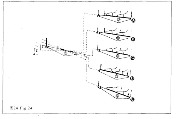
~1.&:ti11=(~24)18. PEDAL OPERATION (Fig.24)
~--~---~
1. ~t&7trm-t-~fl~1jo~1'1=:
1) ~JF;!i~WJMIJti:W?i, fJ1rJf~it~:h3Jo ([}1/GB)
2) JE:-$-~)J
RIIW?i,
J?Jtli:i~"JJ:it~:hJJ oC
11l~1~A)C
~r1:~ fitfftrtfirJ@J~t~J'\:Bt, IJlH~tfftrtfirJ@J~tir*fci, fHrtr.'lJ~~~JJo)
3) ~ biii~WC~¥HifiJfti*::;'i:;SJ.
fJL**f¥
11-.ili~(1:.
ffrr~Ft¥f-r)o (i!l
~C) 4) ~Jfii~WlfriW;tf,Vdi!WfxdJfl
a CIRiJ~E)*
~HHiHJl~~:ff t~4Jfft
[£~.1Jil Z-biiit&
f__;L.i':B:ttffl~tfll:. fn !ijttl9:Jf'Fi'SJ
8~--t-=3o
~ ft~~-f)J15 W;li,
H~~~~
l:.J+ CltJ
;f,;D),H l-A H
:ff~W;Jif&-f-i}-f)Jf6
b';ii, /f~iJ.l.f-T~~:QJf'Fo* tttffthff'J
@J ~r/
1 ,;f.'U;tH&
[u]![¥U
r:jJI'§]{__;'[_i:, ffl~iCJJX:firj@]
~15~ll:.o
*
t£ m fr
~ ~ ~HJJ.r.tt:
1~.& ?;h;JJ
flJ . :Jif mti t& :rM 0 biii,
~ ~ Z9J11=
~~iE -m- m 1-=r o
* fJL ** -JHft ljg
!i; f{l-, ~ll {~f.'f
~f&
[ri]& ¥rJ
rflr§]ffil[,
~tf:
$Jft
ill~~ft lito
*
3tfl~~!L H9l::TTHLJAR:?~BJ, lzp\f.L~{It::H9J::-TkHffi,
i~~biii.f&-'JJf§-~-iJ\:o0
14.
1. The pedal is operated in the following for steps:
1) The machine runs at low sewing speed when you lightly depress the front part of the pedal.@
2) The machine runs at high sewing speed when you further depress the front part of the pedai.@(If the automatic reverse feed stitching has been preset. the machine runs at high speed after in com- pletes reverse feed stitching.)
3) The machine stops (with its needle up or down) when you reset the pedal to its original position.©
4) The machine trims threads when you fully depress the back part of the pedal.@
If your machine is provided with the Auto-lifter (AK-31 ), an addition step is given betwenn the machine stop and thread trimming step.
The presser foot goes up when you lightly depress the back part of the pedal@. and if you further depress the back part, the thread trimmer is actuated.
· If you reset the pedal to its neutral position during the automatic reverse feed stitching at seam start, the machine stops after it completes the reverse feed stitching.
· The machine will perform normal thread trimming even if you depress the back part of the pedal immediately following high or low speed sewing.
· The machine will completely perform thread trimming even if you reset the pedal to its neutral position immediately after the machine started thread trimming action.
· When the machine stops with its needle down. and if you want to bring the needle up, depress the back part of the pedai once.
I
[tl24 Fig 24• 15 •
~*l+t§ fft S1 ifol iJ ( 00 25)
~9JUSTING THE FEED TIMING (Fig.25)
1) {(f,J;~ftll
HW6c F, :rt
iLf-tf~·L'~CD J::J'l'~li:' fvJ~HAl=J J::.$!llm~(i)Et~5E t'I~tJBxt1fa2) iMJ~Bt. M!f'ti~f'H~·Utt: J-.f~Vi"i£{17!!\.~H@, ¥.fi~:f4fAAJ•L'$£~~~Jm:~rnt'IJiJ::., ~frirr~5Et'I~~
He
'JJ r 1\/J Jl t11'4tl
1·Jif5t¥.
~· fJllt~.ill:tli'ULf, llJ:tfti!f4f.lffl·L'$BMM* 1f
rt1~~o4) 1J1Jf'l
kfb1Hf-J~\fif!f. ~i?Xt~~:f-Ht1fl/:, nJ~i!tlf.\ffl•L'~~¥m*tEl&:1JrliH~i0o5) r
J1 1J\.C: +·~::f-fJ:b::fHlffi·L-t~¥tifl1!tA. :t.
/f~t%'0 ~~. ~@nX:ilfrti:fX~o1) To obtain the standard feed timing. align setscrew@ on feed eccentric cam
CD
with setscrew@ on main shaft thrust collarClJ.
2) To make adju.-;tment. loosen two setscrews® to release the feed eccentric cam, properly position the eccentric cam. The retighten the setscrews.
3) To advance the feed timing in order to prevent uneven material feed, move the feed eccentric cam in the direction of the arrow
4) To delay the feed timmg in order to increase stitch tightness, move the feed eccentric cam in the opposite direction from the arrow
5) Be careful not to mo\ e the feed eccentric cam too far, or else needle breakage may result.
- - - · - - - · - - - ,
i
9
1~125 fig.25
20.
~*4 3f 1¥-Jftffi
#-~(00 26)
!Standard feed t1m1ng)
l j
NPPdle~-mThroat
Feed dog plate
:Ie:iog)
20. TILT OF THE FEED DOG (Fig.26)
l)
fiJ~<1Hi0i~Jf;N.hl '1.1#-!H'l
t~fl~ ~~J;\A-"-J ~f~f~CDJJ]~Jf<ls\Bxtifo
2)
17 T IIJJtU'ft£,
~.itHh
fr'lri~b,91iJ tW:f't!J,J
'iEt~H.ffl
!f\.~H:7HE. 3f~M~JJ¥ffi*1irtl
H$J90 ° o3) ~h tii!Jii·tff+(t\Ji~tt. ~:J.S:Hhi~'Jii•JflL iJliJ~r~H'iWVlffri*t11RZJYrtltt.tM9o 0 o
* i1~:
~~ff~M~. ~~~~~~M~. ~ft~~~m~~~~, ffi~. ~~~~§, ~~~-~~
. 16.
l) The standard tilt (horizontal) of the feed dog is obtained when marker dot @on the feed bar shaft is aligned with marker dot@ on feed rocker
CD.
2) To tilt the feed dog with its front up in order to prevent puckering, loosen the setscrew, and turn the feed bar shaft 90 degrees in the direction of the arrow, using a screwdri ve.
3) To tilt the feed dog with its front down in order to prevent uneven material feed, turn the feed bar shaft 90 degrees in the opposite direction from the arrow.
* Precaution
Whenever the feed dog tilt is adjusted, the feed dog height will be changed. So, it is neces- sary to check the height aftertilt adjustiment.
0
Front up0
Standarde
Front downG
Throat plate lt-]26 Fig 2621.
Ji:JJ~jj[(lf!27)21. COUNTER KNIFE (Fig.27)
l .
it } )) J [
JltH&1
BJ,
~:;-~'f)(tft: f AE
JJ CD £fH#
f~ ~'
tid~]JJ-\C Et~tl\ fi: 11 liftl
~ :~L I) ~11 E.K:t>J· ~ JJ !:)\ t,J;i1f~f,f:
'A''WJA)T I!'J ,fJ;iJJ, ~g~ ~-~(1'~K: fi?Jt
tU;J;fiHt'~Ko 2) ~lllfHJJBJJ I;,Ht4/J,
~tx!fi
H<D'~K
IJl?Jt l:tt;J;({f81fflo
vJJ)) b.
ffL fi· rt
1'L'
c.f;j;{fhlftl:
~: 4.0mmI. When the knife sharpness has deteriorated, resharpen counter knife
CD
as illustrated in Fjg. ©.and propely reinstall it.! ) If the mounting position of the counter knife is moved in direction@ from the standard mounting
position. the thread length after thread trimming will be increased accordingly.
2) If the mounting position is moved in direction @,the thread length will be decreased accordingly.
a.Moving knife b. Center of needle c. Standard: 4.0mm
• 17 •
(
rtJ27 Fig.27
22.1¥lt1il:iU8ifcJ~(ag28,
1!129)
22. ADJUSTING THE NEEDLE STOP POSITION (Fig.28, Fig.29)
1. ~ ~€81I.1~H1iL.i[
t.-c-Jtr' j·f~'t-t-f'-"1'-EJ-t·: ±" f-H'' fitij2JAL- [-li:l'- j-Af r t"2:iB"t-'·
l. T!]\fltciH _ ·1Jt 'LEL<E-f :n:::~- ·L_;< "" <J _-ft::. _l-dr3 :::<IL ... N :ito
2)
*ff f·. f'Hl f,[:ffff ?!T 'lf ft.
~l:f't!t~HCD. ?JtPJ
{E t~fiiHt!~ r7'J Vnl~o CD::tH~ H~JJCJilfiJ¥$qJ. W!Jf¥tttk:o
(J)
:be
P,.~jJWJ o
JntH~z9J ,
rnHf ft
N~o
if;$1£1!~~-~H 1 8\Jflii~. i~~~~M;fJl~
!1191',
~-~HI .R~;$1Ef~~DRJ. ~~tfi:l'o 2 l'i~!ft{}lj[I.
"l
Jf~fa lA r11H?i if\
.i~H
j'IJ rt-: frlJ {.! }'~i: llJ,H f H1 T T- f-1; tl
{;)J1'i:,
r-1J
t~f
fiJ Ji ;:h~ ~:%?.~ {<f
f f'f t I f •!
'fi·_H I'Jr
·!.[1 t. t£
f't P.~t J CZl.
~;itnJ t.E K .f* ?t! till r*J imJ
t~ c!t~H?JJAJiif,JftzJJ, ff~HH:
.PJHniJJBhli
11ftiJJ,
f1;HH~oif;$1£f~~~H,2 8\Jflii~. i~~~~M;fJl~
Jlt91'.
~~l}~2 .R~;$1Ef~~DRJ. ~~tR:l'o 1. Stop position after thread trimming1. The standard needle stop position is obtained by aligning red marker dot@ on the machine arm with white marker dot@ on the handv.:heel.
2) Stop the needle in its higheq position, loosen screw
CD
to perform adjustment within the slot of the screw.CD
The needle stop timing 1s advanced if you move the screw in direction©.(J)Thc needle stop timing is delayed if you move the screw in direction@ . Precaution
Do not operate the mach1ne w1th scdrew J loosened. Just loosen the screw. and do not remove it.
2. Lower stop position
1) The lower needle stop position when the pedal is returned to the neutral position after the front part of the pedal is depressed can be ajdusted as follows:
.
I~.
Stop needle
CD
in its lowest position, loosen screw~. and make adjustment within the slot of the screw.Moving the screw in direction
@ ,
advances the needle stop timing. Moving the screw in direction@delays the timing.
*
PrecautionDo not operate the machine with screw
W
loosened. Just loosen the screw, and do notremove it.
I 23. ~f.&ffjJ~~T~.¥(~30)
I 23. PEDAL PRESSURE AND PEDAL STROKE (Fig.30)
1. ~t&WJ~ff1J81i?nJ!l:
1)
im tw
~t& m .iJ.5$ :M:CD
f'l(J1 :z 'll• ffJt
~Eillhim
f~ c2) tt
{-E ~li f~rJ,I± JJ
ifox'J'
03 l H tE 1'1fWrJ. II fJ J1'? }(
c2 ~t&.f6~ff1J81i?nJ!l:
1 )
m 0
~;t;iMJ 1Y
rt~n
~tm ill 1
J iFni'K"
02) ti'~ ill~ W~H. IF
JJm Ao
3 ) i;f[fJ~ if~
11
~n .
i ( fJ i},£ ! J \ r3. ~t&
iT f.¥ En
i?nJ!l:
1 J
:m tv: -tl®tw rrJlr:
f~rJfLr"'J. fr fiiJ>xJJ,
o1. Adjusting the pressure required to depress the front part of the pedal
I) This pressure can be changed by altering the mounting position of pedaling pressure adjust sping
CD
2) This pressure decreases when you hook the spring on the left side.
3) The pressure increases when you hook the spring on the right side.
2. Adjusting the pressure required to depress the back part of the pedal
1) This pressure can be adjusted using regulator screw~-2) The pressure increases as you turn the regulator screw in.
3) The pressure decreases as you turn the screw out.
3. Adjusting the pedal stroke
I) The pedal stroke decreases when you insert connecting rod® into the left hole .
. 19.
[!l30 Fig.30
24.
~t&ft-Jifa1~(0031).
24. ADJUSTMENT OF THE PEDAL (Fig.31)
1. tHH~:i:~iFc.l~:
1) ti::tJf$$J~~if<iJ11f&@. ¥f~~
lffi
t~CDf~ tl:ff~f"t~.j:l[j!~o 2. ~:f.&jfjJi~iFc.l~:1) ~
t& m
ftYrff.:t. 'PJ u -m * tL rr
-t~ l}trn
~1j· n
Et-J ~~~1£
o2) tifEf'~!l\.~fJ@, ~)triJ
U
iJ.l;Jl)t_;Lff~EtJ-l\:Jlo1. Install-ing the connection rod
1) Move pedal® to the right or left as illustrated by the arrrows so that motor control lever
CD
and connecting rod~ are straightened.2. Adjusting the pedal angle
1) The pedal tilt can be freely adjusted by changing he length of the connecting rod.
2) Loosen adjust screw@. and adjust the length of connecting rod~ .
. 20 .
lf]31 Flg.3l
25. -=¥-
~9l1ilJ~i~il( 00 32)
25. ONE-TOUCH TYPE REVERSE FEED STITCHING MECHANISM (Fig.32)
1 1~m:tnt:
I ) f .}1(
r
IB!Efj'rj
~1) r *-CD ' tJl
~ :J}1.fr firJ iii
z:JJf1'
02)
tJ L ;;g
ttlf r
ILl zJJ(:l'rJ tJ
<=-jf. tii r¥ :rr *11m Bl s J li3Jii1J it
0-')) 1 T,-. . r"·J ,'<i lj·· r1 Tl~ J\:19.:, , V·. 1--'-{'fl
fJL
T _u,_ n'rt.A.. 17 '~ Et'-·ff""fr
ttr; ;r,:z_:tcl -t"-"f :>;: J )IIIIi V,:J..L']f\.'-''0 ldf. 'I'' A2. ~ ~:R
fitHiHf =*: 81
~Ji
1) iMJ 'r'J
r
~11;fJrJ
~t Ir X: CD
(!':J r:'~JIJL
H~z N! r NH1
02 J
fti fS'
~\¥H aJ. L
H~ cJJff .k t HJt
11T
if.~ 'f,t ·~li-J rL'11.4L,
1. How to operateI) The moment switch lever
CD
is pressed, the machine performs reverse feed stitching.2) The machine performs reverse feed stitching as long as the switch lever is held depressed.
3) The machine resumes normal feed stitching the moment the switch lever is released.
2. Height of the switch lever
1) Adjust the height of switch lever
CD
so that it can be easily operated.2) Loosen screw
W.
and move the switch lever up or down to adjust its height.• 21 •
[1]32 Fig.32
26.
~~i§(0033~ 0034~0035) 26. WIPER (Fig.33, Fig.34, Fig.35)
1. 1it~H1il:il
~mH~~-*~-~~~~hl~o~-~~~T:
1 )
.wJ
Jr!YfH
1f ~ ~ 'i;IJJ::. t£,
~1:.
$1::1:.
~a
~'J ,~CDxt li
$ -;{.J::.
~gr
~u ,~ ~ o 2) ~~~ff.Jiilfill tl:-f:JtJl ft 9
,C.,~ff§Ji\:};] l~*o~-~U€~~~~Srr®~MSU~~@U~~~~~ffo 3) ~~~~~ffl~~~Bj, iA'tJJltJT~~~ff'ko
1. Positioning the wiper
Adjust the ~osition of the wiper according to the thickness of the material sewn. The adjustment procedure is as follows:
1) Turn the hand wheel in the normal direction of rotation to align white marker dot
CD
on the hand wheel with red market dot~ on the machine arm.2) Adjust the distance between the flat part of the wiper and the center of the needle to 1 mm.
Tighten wiper adjust screw® so that the wiper is pressed and fixed by wiper collar@.
3) When the wiper is unnecessary, turn wiper switch (J) OFF.
!1)33 Fig.33
. 22.
1!135 Fig.35
L2n.Jj!:fil!
27. SPECIFICATIONS J
GC
188-M-D~Model GC188-M-D
~iN ~
J9-:f4 J=H Application For medium-weight
materials
tit~ It~
* ffj )J\. f+P 50 0 0 'ft Sewing speed Max.5000 s.p.m.
-
Ht:& -K f5t 4mm Ckz-k) Stitch length Max.4mm
n
dt!~m: f+
~rn: 1 Omm Ch fff:) Presser foot lift 1 OOmm (Standard)
ij.?. 'll( *ff{)
13mm (:fti:k) (by knee lifter) 13mm (max.)
tJL t I DBX1"14 Needle DBX1"14
if1J iff IUJ 1 o
~-(J/UJ Lubrication oil 10 white oil
. 23 .
Parts Book
GC 1 &B-M-0~ (t:p~}fH~JtJ)
Model GC 188-M-D (For Medium heavy Material)
1,
;ffl~51'~.§.1!f:1.Arm bed components
rr~
14
~ ~ ~ ~~Ref. No. Part No. Description Amt
GQ228 ~~ ~
H* .. · · ... ·. · · ... · · · ... · · ·
Model plate ... · 1 2 GX565ru!
1i5-!i~H~nn ... · .. · · .. · · .. · .. · · · · .. · .. ·
Model plate rivet · ... · 2 3 GS0548Iff ;f&
5[t1 .. · .. · .. · .. · · .. · .. · · · .. · .. · .. · .. · .. ·
Bed screw stud ... · · .... · .. · .. · 4 4 GK239 !§-00 t& .. · · .. · .... · .. · · · · .. · · · · .. · · .... · .. · .. · .. · Side plate · .... · .... · .... · .... · .. · .. · 5 GR3340 !§-@;f&
~... · · · .. · .... · .. · .. · .. ·
Gasket .... · ... · .... · .. · .... · · 1 6 GS053 500t&!l!..'*fT12/64-28 L=9 ... Screw 12/64-28 L=9 ... 8 7 GR5685 [§] t& .. · .. · .. · .. · .. · .... · · · .... · · · .. · .. · · · Face plate arm .. · .. · · .. · .. · .... · .. · 8 GQ277 rn:J;f&
~ ttp;f& ... · · · · . · · · .. · · · ·
Decorative Plate .. · .. · .. · · .... · .. · .. · 1 9 GR'5686 [§];f&
~... · ... · · .. · .. · · · ·..
Gasket ... · ... · .... · 1 10 GS053 llffi&!l!..'*fT12/64-28 L=9 ... ··· Screw 12/64-28 L=9 ... 3 11 GR1458liD ;f& 1m li
!!!..'* JL ~ .. · .. · · .... · .. · · · · .. · .. · · · Rubber plug .. · · .... · .. · .. · .. · .. · .. · 2 12 GR1463 Hiff!Em!I!..'*JL~ ... ··· ··· ··· ... ··· Rubber plug ... ... ... 1 13 GR3344ME .tit Jl
iff~!!!..'* JL ~ .. · .. · .. · · .. · .. · · · Rubber plug 2 14 GR3345 j!f-timl1~JL~ ... ··· ··· ··· ... ··· ··· Rubber plug ... . 15 GR1464 Ttmll'rJL~ ... ··· ··· ··· ··· ... ··· Rubber plug ... ..16 GR2045