Investigations On The Influence Of Process
Parameters On Damage Factor During
Drilling Of Glass Fiber Reinforced
Composites
R.Raja1, Dr.G.Chandramohan2, Dr.A.S.Varadarajan3
1 R.Raja is Assistant Professor in School of Mechanical Sciences, Karunya University, Coimbatore, 641114, Tamil Nadu, India. (e-mail: raja_r11773@karunya.edu).
2 Dr.G.Chandramohan is Principal of Karpagam College of Engineering, Coimbatore, 641032, Tamil Nadu, India
3 Dr. A S Varadarajan, is Head of the Department in School of Mechanical Sciences Karunya University, Coimbatore, 641114, Tamil Nadu, India. (e-mail: varadarajan_as@yahoo.co.in
Abstract— Abstract: Drilling is an essential operation during the assembly of the structural frames of automobiles and aircrafts made of fiber reinforced composites. The life of a joint, especially the fatigue life depends on the quality of the hole drilled. A hole with minimum damage factor can bring forth better life and aesthetic to the joint formed. The present investigation aims at arriving at a set of cutting parameters and compositional parameters to minimize damage factor during drilling of glass fiber reinforced composites. The spindle speed was varied at three levels namely 142, 210 and 450 RPM .The chisel angles were kept at 90,100 and110 degrees and three orientations were selected for the glass fibers namely 90 degrees, 45 degrees and random orientation. A nine run experiment was designed based on Taguchi’s technique and the experiments were carried out with five replications. It was observed that a spindle speed of 450 RPM, a chisel angle of 110 degrees and a random fiber orientation can bring forth better holes with minimum damage factor .Confirmatory experiments were conducted to check the validity of the predictions .The experimental results matched well with the predictions
Keywords—Damage factor, fiber orientation, chisel angle
1. Introduction
Drilling is one of the most y important machining operations because it is often a final operation during assembly. Any defects lead to rejection of the part. For example In the aircraft industry about 60% of parts are rejections during the final assemble of an aircraft due to defects in drilled parts. [1] C.Tagliaferri et al. [2]. Carried out experiments on GFREC composites and came out with a set of machining parameters Experimental results showed that, the quality index was strongly affected by cutting speed to feed ratio. Large damage to obtain defect free holes of good quality. zones were observed when low cutting speed to feed ratios were adopted . The research work done by Paulo et al[3] using helical flute stub drill and a brad spur type drill indicated that the type of drill used has a profound influence on the quality of the hole produced. The effect of cutting speed and feed on the size of delamination was investigated by C.C. Tsao [4] and an attempt was made to define the mechanisms responsible for delamination. He defined a peel –up delamination at the entrance and a push out delamination at the exit. By carefully controlling the geometry of the drill an d the cutting parameters it is possible to obtain holes with minimum delamination at the entrance and the exit. The influence of the geometry of the drill bits on the quality of the hole drilled was investigated by C.C. Tsao [5] and came out the following mechanism of delamination
2. Body of Manuscript
possible to obtain holes with minimum delamination at the entrance and the exit. The influence of the geometry
of the drill bits on the quality of the hole drilled was investigated by C.C. Tsao [5] and came out the following
mechanism of delamination
Fig. 1 Mechanism of delamination
Preparation of GFRECs
Glass Fiber Reinforced Epoxy Composites (GFRECs) consisted of glass fiber in an epoxy matrix; it was manufactured by hand lay up method. [6] The reinforcing material was laid at three orientations. The first orientation consisted of an arrangement in which the glass fibers were orientated at 90 degree with each other. The second orientation consisted of an arrangement the glass fibers were kept at an angle of 45 degree with each other. in the third arrangement fibers were oriented at random. six such layers were in all the three specimens and all of them had the same volume fraction that is 35% of the matrix consisting of epoxy resin
Selection of Drill bits
All available drills such as core drill, stub drill and twisted drill(HSS) have their own advantages and limitations with respect to drilling of composites [7] .in this work High Speed Steel (HSS) drill bits with 3 chisel angles namely 90 degree, 100 degree and 110 degree were used for this investigation. The drill bits had the diameter of 5 mm and identical in all aspects except in chisel angle
Selection of drilling parameters
Spindle speeds were fixed at three levels namely 142 rpm, 210 rpm and 450 rpm
Design of experiment
A 9 run experiment, with three input parameter each varied at with three input parameter each varied at 3 levels on Taguchi technique and design matrix is shown in Table 1. Parameters which
TABLEI
PROCESS VARIABLES AND THEIR VALUES
Factor Level 1 Level 2 Level 3
Speed (rpm)
142 210 450
Chisel angle 900 1000 1100
Reinforcement (fiber) orientation
900 450 Random
TABLE2
CONSTANT PARAMETER AND ITS VVALUE
Parameters Values
Feed (mm/rev) 0.21mm/rev
Fiber fraction
In composite 65% by weight
II EXPERIMENTAL SET UP The important equipments used in experimentation included
Drilling machine. The drilling machine used for the experiment is a upright type drilling machine. The machine can be used as an automatic feed machine or a manual feed machine. It has controls that allow its use as an automatic feed machine. The upper lever allows selection of automatic feed in three levels - .11 mm/rev, .21 mm/rev, .31 mm/rev. Once the required level is selected the lower lever has to be pulled forward for the machine to start automatic operation.
Profile Projector
The profile projector is used for measuring the drilled holes after completing the drilling operation. The GFREC piece is mounted on the worktable of the profile projector. The specimen is focused by adjusting the position of
the table to get a clear sharp image [8]. The focusing shouldbe done properly to ensure that the damage area
around the drilled hole is clearly visible. A magnified image of the GFRECpiece isobtained on the screen of
the profile projector. Magnification in the range of 10 xs, 20 xs and 50 xs are possible using the instrument. Going for a higher magnification allows for easier measurement of the drilled holes. Both linear as well as angular measurements can be done using the profile projector.
Cylindrical Grinder
A Cylindrical Grinder was used for precisely grinding the drill tools. Drill tool angles are 900, 1000 and 1100
I. RESULTS AND DISCUSSION
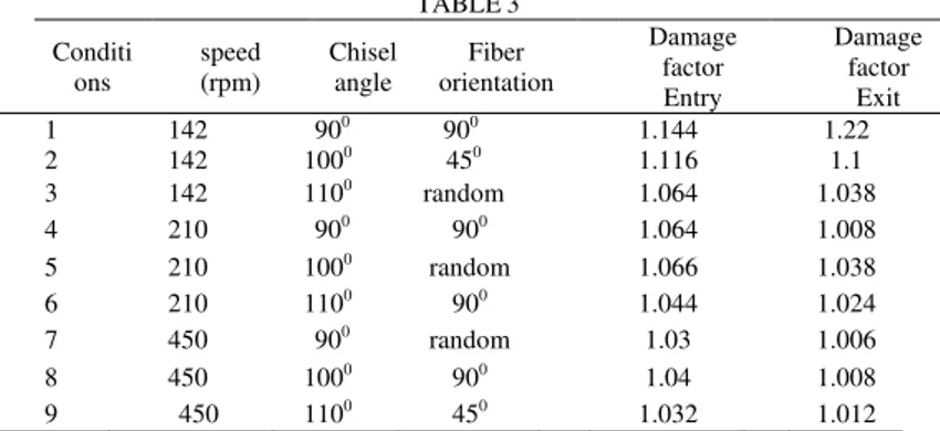
TABLE3
Conditi ons
speed (rpm)
Chisel angle
Fiber orientation
Damage factor Entry
Damage factor
Exit
1 142 900 900 1.144 1.22
2 142 1000 450 1.116 1.1
3 142 1100 random 1.064 1.038
4 210 900 900 1.064 1.008
5 210 1000 random 1.066 1.038
6 210 1100 900 1.044 1.024
7 450 900 random 1.03 1.006
8 450 1000 900 1.04 1.008
9 450 1100 450 1.032 1.012
An attempt was made to arrive a set of levels of input parameters to achieve minimum damage factor using response table methodology. The levels of input parameters to achieve minimum damage factor is summarized in table 4
TABLE4
LEVELS OF OPERATING PERFORMANCE FOR OPTIMUM PERFORMANCE
Desired outcome
Speed (rpm)
Chisel angle
(degree)
fiber orientation Low damage
factor(Entry) 450 1100 Orientation Random
Low damage
factor(Exit) 450 110
0 Random
For achieving minimum damage factor, the spindle speed should be kept at its high level, the chisel angle and the orientation should be kept at level 3.in other words the spindle speed should be its maximum at 450 rpm and the chisel angle
At 1100 and the fibers to be oriented at random to achieve minimum damage factor at the entry and exit of the
holes. When the spindle speed kept at high level that is at 450 rpm, the fibers are cut rapidly, the fibers will not get time to elongate or deform as fracture occurs instanteously.high speed cutting creates cracks on the fiber surface which propagates resulting in the ultimate failure at a rapid rate, this prevents pull out fibers that can lead to enlargement of holes. This argument supported by the fact that a progressive decrease in damage factor observed as the spindle speed from level 1 to level 2 and then to level 3 as shown in figure 2
1 1.02 1.04 1.06 1.08 1.1 1.12
s1 s2 s3 d1 d2 d3 f1 f2 f3
Spindle speed, Drill angle, Fiber orientation
1.067
D
a
ma
ge Fa
ctor
(
e
nt
ry)
Fig. 2 Relative significance of operating parameters on damage factor(entry)
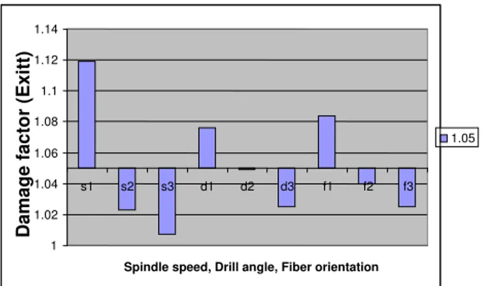
Fig. 3 Relative significance of operating parameters on damage factor(Exit)
when the spindle speed is low the fibers cut rapidly and the movement of fibers during cutting g operation can create damage to the matrix material which will lead to enlargement of holes drilled that results in higher values of damage factor. it is seen that chisel angle at level 3 that is at 1100 bring forth minimum damage factor. It is seen that there is gradual decrease in the damage factor as the chisel angle increases. when the chisel angle is high, the fibers are cut instantaneously and the drilling operation resembles punching of holes in metal forming, where the diameter of the holes produced initially is almost equal to the diameter of the drill, but when the chisel angle is low, the drilling operation resembles piercing. the fibers and the surface will be pulled down into the hole as the drill bit moves down causing damage to the matrix around the hole..in this case the final diameter of the drill bit is reached gradually and by the time it becomes equal to the diameter of the drill bit, sufficient damage is done to the matrix material. it is seen that gradual decrease in the damage factor as the chisel angle
increased from 900 to 1100it is observed that a random fiber orientation can result in lower damage factor
when compared to 900 and 450 orientation. When the fibers have, they show grater tendency towards pull out as
in the case of pulling a fiber from a bundle of fibers with a regular parallel orientation. When the fibers are randomly oriented tendency for pull out reduces as the movement of individual fibers is obstructed by the fibers in the vicinity. When the fibers are regularly (900) oriented, weakening of the matrix takes place
Due to the free movement of the fibers which leads to the damage of the matrix around the hole drilled leading to its enlargement. But when the fibers are randomly oriented damage to the matrix surrounding the hole is reduced considerably due to fiber pull out ,on account of greater resistance to the movement of interacting fibers
1 1.02 1.04 1.06 1.08 1.1 1.12 1.14
s1 s2 s3 d1 d2 d3 f1 f2 f3
Spindle speed, Drill angle, Fiber orientation
Damage facto
r (Exitt)
which are interlocked.considearble amount if variation in the value of damage factor is not observed when the fiber orientation
Similar explanations can be given to the observations indicating the relative significance of the input parameters on the damage factor at he exit
.
TABLE5
Levels of operating parameters for optimum performance
Speed (rpm)
Chisel angle
(degree)
fiber orientation
450 1100 Orientation Random
.confirmatory experiments were conducted to validate the observation from the response table to achieve the minimum damage factor accordingly experiment were conducted in which the speed was kept at 450 rpm, chisel angle was kept at
1100 and fiber were oriented randomly. The damage factor was measured, which was lesser than the smallest
damage
factor observed in the whole set of readings
CONCLUSIONS
It is observed that the cutting speed, chisel angle and the orientation of fibers in the composite have their own
influence on the damage factor. Cutting speed 450 rpm, chisel angle1100 and the random orientation of fibers in
the composite can be recommended for achieving minimum damage factor in drilling of holes in GFRCC
ACKNOWLEDGMENT
The authors are grateful to the Centre for Design and Manufacturing Engineering (CRDM) of School of Mechanical Sciences, Karunya University for providing the facilities to carry out this research work. The authors would like to thank Mr J.Jones Robin and Mr K.Siva Sankaran for their assistance and help.
REFERENCES
[1] El-Sonbaty, U.A.Khashaba, T. Machaly, Factors affecting the machinability of GFR/epoxy composites, Department of Mechanical Design and Production Engineering, Faculty of Engineering, Zagazig University, P.O. Box 44519, Zagazig, Egypt, 2003.
[2] V. Tagliaferri, G. Caprino, A. Diterlizzi, The effect of drilling parameters on the finish and mechanical properties of the GFRP
composites, International Journal of Machine Tools and Manufacture, 30(1), 77-84, 1989
[3] J.Paulo Davim, Pedro Reis, C.Conceicao Antonio, Experimental study of drilling glass fiber reinforced plastics (GFRP)
manufactured by hand lay-up, Department of Mechanical Engineering, University of Aveiro, Campus Santiago, 3810-193 Aveiro,
Portugal, Received 7 November 2002; received in revised form 12 June 2003; accepted 21 June 2003.
[4] C.C. Tsao, H. Hocheng, Taguchi analysis of delamination associated with various drill bits in drilling of composite material, Department of Power Mechanical Engineering, National Tsing-Hua University, Hsinchu 300, Taiwan, ROC, Received 6 October 2003; received in revised form 10 February 2004; accepted 26 February 2004
[5] C.C. Tsao, The effect of pilot hole on delamination when core drill drilling composite materials, Department of Power Mechanical Engineering, National Tsing-Hua University, Hsinchu 300, Taiwan, ROC, Received 6 May 2005; received in revised form 15 August 2005, accepted 22 August 2005
[6] Lubin G. Handbook of composites. New York: Van Nostrand Reinhold Company Inc; 1982.
[7] C.C. Tsao, H. Hocheng, Effects of exit back-up on delamination in drilling composite materials using a saw drill and a core drill,
Department of Power Mechanical Engineering, National Tsing-Hua University, Hsinchu 300, Taiwan, ROC, Received 18 October 2004; accepted 13 January 2005
[8] J.Paulo Davim, J. Campos Rubio, A.M Abrao, A novel approach based on digital image analysis to evaluate the delamination factor
after drilling composite laminates, Department of Mechanical Engineering, University of Aveiro, Campus Santiago, 3810-193