EFFECT OF LOW VELOCITY
REPEATED IMPACTS ON
PROPERTY DEGRADATION OF
ALUMINUM-GLASS FIBER
LAMINATES
G.R.Rajkumar*1, M.Krishna1, H N Narasimha Murthy1,.S C Sharma2, K.R.Vishnu Mahesh3
1. Research and Development, Department of Mechanical Engineering, R V College of Engineering,
Bangalore-560 059, India,
2. Tumkur University, Tumkur, India
3. Department of P.G Studies and Research in Industrial Chemistry, Kuvempu University, India
Abstract
The objective of the paper was to experimentally investigate the effect of repeated low velocity impacts on tensile strength of fiber metal laminates (FML) using instrumented drop weight impact tester. FMLs were fabricated layer by layer such as three layers of aluminium6061 and two layers of glass fiber reinforced epoxy plastics. The FMLs were subjected to repeated low velocity impacts (<10 m/s) at the same location on the FML. The degradation of mechanical property due to impact(s) was studied using Zwick UTM at distances of 0, 20, 40 and 60 mm from the impact point. Results indicate that ultimate tensile strength, failure strain and ductility of all specimens initially decrease and then remain constant with increase in number of impacts. A closer examination of impacted FML by Scanning electron microscope indicates that thinning and shear fracture in aluminum layers as well as delamination and fiber failure in composites plies were present.
Keywords: FML, low velocity impact, tensile strength, delamination
1. Introduction
The fiber metal laminates (FMLs) are relatively new type of material developed from the need for high performance light weight structures with excellent properties under the tensile, flexure and impact conditions. They combine the good characteristics of metal such as ductility, impact and damage tolerance and fiber reinforced composites such as high specific stiffness, corrosion resistance and fatigue resistance of fiber reinforced composites [1], which finds applications in aerospace industries. FML with outer metal sheets as Aluminium or steel and inner layer FRPs as Glass fiber reinforced polymers or Carbon fiber reinforced polymers or Aramid fiber reinforced polymers along with Al plates [2]. However FMLs are very susceptible to impact damage, such as thinning of aluminum sheets delaminating between metal and FRP, matrix cracking and fiber failure [3,4]; these damages possess significant reduction in the strength and stiffness of FML.
Addullah & Cantwell [5] showed that the multilayered laminates require high impact energy to that of sandwich laminates for perforation given the same thickness. At low velocity impact a failure of FML in glass fibers was never detected before cracking of outer aluminium, hence the aluminum plate acts as a sacrificing layer [6]. Carrillo & Cantwell [7] reported that during impact, the fiber-metal interface does not deboned, suggesting a high degree of adhesion across the interface. In addition, in FML laminates in both systems (Al and FRP) exhibited a localized indentation failure was followed by progressive collapse of the laminate at higher impact energies. A better understanding of interfacial properties, characterization of interfacial adhesion strength and failure mechanisms under repeated impacts on FML is therefore required for evaluating the degradation of mechanical properties.
2. Experimental studies
A Square plate (180 mm x 180 mm x 0.8 mm) made of Al6061 was used for FML. Bi-direction woven roving glass fiber of 600 gsm was reinforced with epoxy (LY 556 with HY556 hardener) of 0.175 mm thick for each layer. The GFRP are oriented parallel to the edges of Al panels and stacking sequence of AGAGA (A-Al & G- GFRP). Since GFRP are more prone to absorb moisture from atmosphere, the Al used on exterior surface of FML prevents moisture absorption. Before stacking, the Al sheets were cleaned with acetone to remove grease and dirt. Cleaned Al plates were chromated for better adhesion between layers. FML panels were prepared by hand layup techniques followed by heating to 150 C under pressure of 1 bar for five hours and cooled to room temperature. Four specimens were used for each condition and average value is taken for discussion.
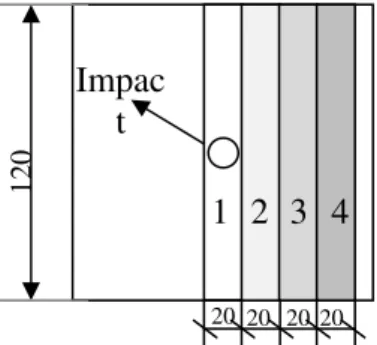
An Instron Dynatup drop tower make 8250 is used for low velocity impact test. The machine is capable of impacting samples at energy up to 302 Joules. The FML specimen was clamped at the bottom of the machine between the two rectangular blocks which has square opening at the center. The hemispherical tup of diameter 12.5 mm was used as impactor with 5.2 kg weight controlled by solenoid switch. The drop height was maintained 80 cm for all conditions. After impact the tup was captured by a stopper to avoid rebound. A velocity detector measures the velocity of tup just before it strikes the specimen. For each experimental study a total of 4096 data points were collected during impact event by data acquisition system. The number of impacts was varied from 1 to 4. The impact energy is expected to increase for specimen which are already impacted due to the extra height / distance gained by the damaged specimen. Impact parameters such as energy at maximum load, deflection at maximum load and impact velocity are evaluated from the data obtained from data acquisition system. The photographs of the front and back face of the impacted specimens were taken to study the failure modes. As per Wu and Wu [8] the four tensile straight sided specimens (120 mm x 20 mm x 4.5 mm)
were cut as shown in Fig. 1 after impacts. The tensile strength test for each strip was carried out on Zwick /
Roell Z-100 universal testing machine at strain rate of 10 -3
/s up to failure of the specimen.
Results and discussion 3.1 Impact studies
Fig 2 (a) shows the variation of load with time. It can be observed that the force lasts for 8 ms for the first impact and then it reduces for subsequent impacts to 5, 4 and 4 ms for second, third and fourth impacts respectively. Although the magnitude of the repeated impact is the same for all tests, different force waves propagate though the different impacts. The first impact attained a maximum load of 3.2 kN between 3 and 4 ms, second impact attained a maximum load of 4 kN between 3 and 3.5 ms, third impact attained a maximum load of 4.6 kN at 2 ms and fourth impact maximum load at 3.1 kN between 2 and 3 ms. During first impact the tup impacted on FML surface with a point contact. The contact surface area between tup and FML subsequently increases hence the load-time curve is flattened. After first impact there was spring back due elastic recovery of FML. In second impact due to higher contact area between tup and FML impact the curve becomes flatter and the specimen is partially damaged. In third impact area of contact is predominantly higher than first two impacts hence the peak is sharper and time drastically reduce. The specimen is then fully damaged. At the fourth impact the tub pierces through specimen, the applied load is utilized for bending of specimen instead of damaging. Hence the load decreases and the curve looks flattened.
Fig. 2 (b) shows the variation of observed energy of FML with time (ms) of the impact. The energy / time curve shows the similar behavior of load-time curve. But all the specimen show that twice the time was taken to reach zero energy status compared to load-time curve. As per law of conservation the energy (KE) is maximum when the load (PE) attained is minimum as shown.
Fig. 2(c) shows impact velocity for impact time and number of impacts on FML. All four curves show decrease
1 2 3 4
Impac
t
20 20 20 20
1
20
in trend because of resistance offered by the FML. First impact takes longer duration (8 ms) and subsequent impacts took half of the duration of first impact. This may be caused for two reasons i) initially, the FML is flat having an undefined radius, but in subsequent impact there exists an indentation and a finite radius of curvature in the contact zone and ii) first impact will be in contact with relatively softer matrix than subsequent impacts.
The energy absorbed at each impact event is as shown in Fig. 3(a) for the FML. In first impact, the energy absorption is lower than other impacts but during second impact energy absorption is the maximum then it decreases. Both metal layer and fibers are the load bearing components, characterized by fiber and metal layer on the impacted face being in compression and on the other side being in tension. When the FML is first impacted, the fibers and metal layer store most of energy and little is dissipated as matrix cracking. In second impact the higher energy is dissipated as matrix cracking which appears as a curve. A drop in energy in third and fourth impacts may also be attributed to some form of damage, which may also be referred to as loss of stiffness with some strain energy stored, which later may be dissipated. The release of this energy helps to dampen the impact force and generate reactions to set the bodies apart.
The increase of the velocity of an impact event with the number of impacts could be expected because the plates are more damaged, at least locally under the indenter and therefore, they are more compliant. Therefore, when subjected to the same force, a damaged structure will deflect more, increasing the velocity at contact between
Fig. 2. Impact response (load, energy & velocity) of Al/fiber laminates function impact time
.
Time, ms
Ener
gy,
J
Velocit
y,
M/
s
Load
the indenter and the specimen under the point of impact as shown in Fig. 3(b). The damage behavior observed reflects the restrictions imposed by the fiber to the composite to deform and as the number of fiber directions is increased [9]
As the number of impacts increases, damages increase as also deflection of the FML as shown in Fig. 3(c). This is not surprising given that the number of impacts lead to more damage of FML system. An examination of the perforated samples highlighted the presence of significant delamination between the composite and Al alloy layers. Also present were regions of localized fiber fracture associated with the perforation process and extensive shear fracture in the upper and lower Al alloy skins.
Fig. 3 Impact response (energy, impact velocity & deflection) of Al / fiber laminates function of number of impacts.
Ener
gy
at maximum load,
j
Im
p
act velocit
y
, m/s
Deflec
3.2 Impact damage mechanism
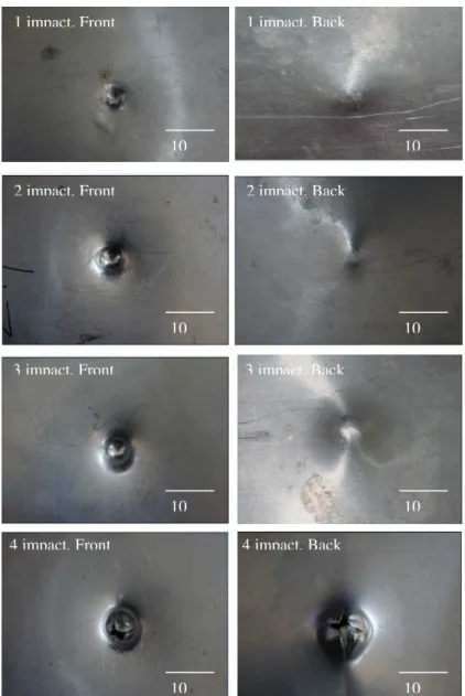
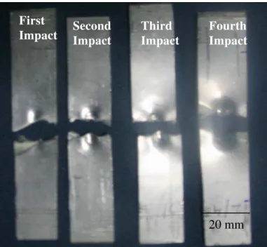
The damage mechanisms (modes) examining the front and rear surface of the impact-damaged samples are shown in Fig 4. The impact images are placed according to the sequence of impacts. In first impact (Fig. 4(a)) damage takes the shape of circular dent at front end and followed by localized bend at the back surface. As the number of impacts increases the shape of the dent although circular, increases in size. During second impact, a large dent and then a circular crack developed around the impactor and the uppermost aluminum layer. Then the fiber plies tries to push though the rear surface opening, but due to sufficient structural support given by layers and back face as shown in Fig. 4(b),this does not happen. A similar damage trend can be seen in third impact due to high strength of the back face to resist further damage as shown in Fig. 4(c). Increasing the number of impacts resulted in significant thinning of the back face metal layer prior to fracture. Here, the composite layer also fractures whilst the front face aluminum layer remains intact hence a cross shaped petalling is seen on the rear side (Fig.4 (d)). Finally the FML was fractured following fourth impact. Front face exhibits smaller deflection whereas the back face deflection is more because the back layer absorbs most of the energy.
Scanning Electron microscope was used in order to highlight the damage modes in the fiber-metal laminate interface subjected to low velocity impact loading. The front face and back face deformed differently, particularly at the point of impact. This was due to the presence of transverse shear and through-thickness deformations in between layer. Fig. 5 shows the relative deformation of the front face and the back face surfaces. The centerline radius of curvature of the back face surface is greater than that of the front face surface.
1 impact, Front 1 impact, Back
2 impact, Front 2 impact, Back
3 impact, Front 3 impact, Back
4 impact, Front 4 impact, Back
10 10
10 10
10 10
10 10
10 mm
Delamination
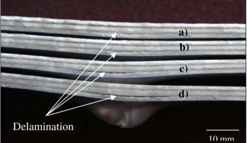
Fig. 5. Low magnification optical micrographs of cross section of Al FML ( a-one impact, b-two impacts, c-three impacts and d-four impacts specimens)
a)
b)
c)
d)
Fig. 6. SEM showing the impact damage on Al / glass fiber FML. a) 1 Impact Sectional view, b) 2 Impact Sectional view, c) 4 Impact Sectional view
Matrix crack at interface
Matrix Crack
Matrix Crack
Fiber fracture
Al tear
a)
b)
From these observations, it is apparent that the effect of transverse shear and through-thickness deformations are important. Delamination occurred between the layers, because of limitations in adhesive bonding. This causes a greater drop in the shear strain than the bending strain due to permanent deformation in the layers.
Fig. 6 shows response of inner layers against external impacts. Even at first impact, the delamination within the composite layers was more pronounced with reference to back face layers as show in Fig. 6(a). The delamination and deformation having semi-circular shape along with interlayer and intralayer matrix cracks. In third and fourth impacts several damage modes can be seen in Fig. 6(b) and Fig. 6(c) respectively. The damage modes such as delamination, fiber breakage and matrix cracks occur in both matrix and composite layers. The back face experience larger inelastic deformation than the front face because the layers in the front face are supported by the layers behind. More delamination occurs on back face because local curvature leads to greater material strain on back face than the front face i.e. the damage is conical with the maximum damage on the back surface.
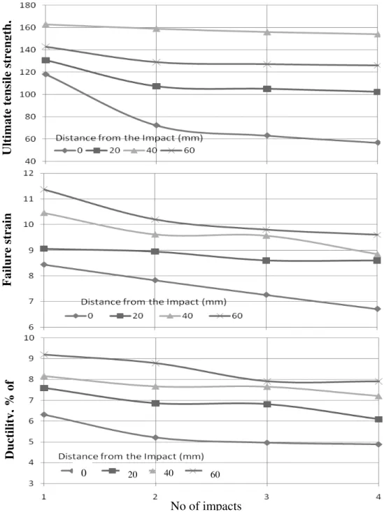
No of impacts
Fig. 7 Effect of number of impacts on mechanical properties of Al/fiber laminates a) Ultimate Tensile Strength, b) Failure strain and c) Ductility (% of elongation) respectively.
Ultima
te te
nsile s
tren
g
th
,
Failure s
tra
in
Ductilit
y,
%
of
3.3 Effect of impacts on tensile strength
Investigations into post-impact load bearing capabilities of FML involving different modes of stressing have received a lot of attention. It is of particular interest to understand to what extent the impacted materials can sustain further loading. It has been found that tensile strength is reduced when impact damage is present in the specimen [10]. In this study, tensile testing was carried out to evaluate post impact properties namely tensile strength, failure strain and ductility. It was anticipated that a correlation between the impact energies the damage magnitudes and tensile properties would be established.
The relationships of tensile properties (UTS, failure strain & ductility) with number of impact are illustrated in Fig. 7. It indicates that number of impacts results in reductions in UTS, failure strain and ductility to varying degrees. Comparatively, UTS is more severely affected by impact damage, leading to higher degradation. Degradation of UTS is more at the impact point and it reduces at distances away from impact point. The maximum UTS reduction is approximately 25%. This higher sensitivity can be explained by the fact that the impact damage is localized in most cases and therefore it has less effect on global properties such as UTS, failure strain and ductility. Although GFRP composite layers have good strength and specific stiffness but as poor energy absorption (impact) is the main weakness of GFRP layers which leads to delamination between GFRP and aluminum layers. Fig.8 shows the modes of failure at impact zone for number of impacts. The mode of failure generally changes from global, to local, to mixed mode as the delamination length increases. Fracture damage mode interaction must also be understood when attempting to predict initiation and propagation of a particular form of damage. For first and second impact, specimens showed irregular fracture (ductile failure)
surface on both aluminum and GFRP layers, because the glass fiber can reduce matrix-dominated damage. For
third and fourth impact specimens showed straight fracture (brittle failure) which is related to the major damage mode. This is due to a combination of tensile and higher impact energy (repeated impacts).
3. Conclusion
The study presents an experimental investigation of mechanical degradation of flat glass fiber epoxy aluminum plates which were subjected to repeated low velocity impacts. The specimens were tensed after impact. On the basis of the experimental data collected the main conclusions are as follows:
Peak load, impact energy and failure strain decreased with increasing number of impacts due to degradation
of FML
There is sudden drop of UTS after first impact but has little significance as number of impacts increased.
Degradation of UTS is more at the impact point and subsequently lesser as we move away from the point of
impact but decreases again at the end of the specimen due stress waves.
Failure mechanism during penetration impacts is preferentially dominated by the plastic deformation of the
glass fiber epoxy and resulting penetration mode is highly localized, almost similar to cross shaped hole.
The damage consisting of residual plastic deformation, delamination and even aluminum cracking is found
in the FML with increasing the number of impacts.
First
Impact
Second
Impact
Third
Impact
Fourth
Impact
20 mm
References
[1] S.M.R.khalili,R.K.Mittal,S.Gharibi Kalibar A study of mechanical properties of Steel/Aluminum/GRP laminates, Material science and Engineering A, 412, 2005, 137-140
[2] G.Caprino,G.Spataro,S.Del Lluongo Low velocity impact behaviour of fiber glass aluminium laminates,Composites Part A, 35, 2004, 605-616.
[3] B.M.Liaw, Y.X.liu and E.A.Vilars Impact damage mechanism in Fiber metal laminates Proceedings of the SEM annual conference on Experimental and applied mechanincs June 4-6, 2001, Portland, Oregon 536-539
[4] Y.X.Liu and B.M.Liaw, Drop weight impact on Fiber metal laminates using various indenters.Proceedings of SEM X International congress and Exposition on Experimental and Applied mechanics, Costa Meas, CA, June 7-10, 2004, Paper no 386.
[5] M.R.Abdullah and W.J.Cantwell Impact resistance of polypropylene-based finer metal laminates.Composite sscience and technology, 66, 2006, 1682-169.
[6] Vlot A. Impact loading on fiber metal laminates. International Journal of Impact Engineering 18(3), 1996, 291–307.
[7] J.G.Carrillo, W.J.Cantwell Mechanical properties of a novel fiber metal laminates based on a polypropylene composite, Mechanicas of materials 41, 2009, 828-838
[8] H.F. Wu, L.L. Wu, A study of Tension test specimens of laminated hybrid composites, Composites Part A, 27, 1996, 647–654. [9] W.A. de Morais a, S.N. Monteiro b, J.R.M. d’Almeida, Evaluation of repeated low energy impact damage in carbon epoxy
composite materials, Composite Structures, 67, 2005, 307-315.