www.ache.org.rs/CICEQ
Chemical Industry & Chemical Engineering Quarterly 14 (3) 173−180 (2008) CI&CEQ
173
BAHAR HOSSEINI1
GHASEM NAJAFPOUR DARZI2
MAEDEH SADEGHPOUR1
MOSTAFA ASADI1
1School of Environmental Engineering, Faculty of Civil Engineering, Noushirvani, Babol University of Technology, Babol 2Faculty of Chemical Engineering, Noushirvani, Babol University of Technology, Babol, Iran
SCIENTIFIC PAPER
UDC 628.3.03.034.2:628.356
THE EFFECT OF THE SLUDGE RECYCLE RATIO
IN AN ACTIVATED SLUDGE SYSTEM FOR THE
TREATMENT OF AMOL'S INDUSTRIAL PARK
WASTEWATER
An activated sludge aeration tank and a sedimentation basin were used to treat Amol’s industrial park effluents originating from all industrial units. A con-tinuous system was implemented and the kinetic parameters were measured. The parameters such as rate constant, substrate utilization rate constant, yield
and decay coefficient were 2.12 d-1, 232.4 mg l-1, 0.33 g/g of substrate and
0.096 d−1, respectively. The hydraulic retention times (HRT) were in the range
of 9 to 27 h. The sludge recycle ratios in the range from 0.3 to 1 were consi-dered. The COD removal, SVI and DO were determined and the optimal va-lues were obtained. It was observed that at HRT of 16 h and the sludge recycle ratio of 0.85, the COD removal and SVI were 95 and 85 %, respectively. The sludge recycle ratio greater than 0.85 had no significant effect on the COD removal.
Key words: activated sludge; COD removal; industrial effluents; sludge recycle ratio; SVI.
The water shortage around the world is more severe and also greater attention is paid to reuse wastewater from municipalities and industrial plants [1,2]. Both municipal and industrial wastewaters are often treated aerobically by an activated sludge pro-cess [3-6]. The activated sludge propro-cess is widely used for the wastewater treatment, as it is reliable, efficient and capable of producing high quality effluent and is also, comprised of a biological reactor along with a secondary clarifier [7-11]. This process is ex-tensively considered as a secondary wastewater treat-ment [12,13]. The microorganisms perform oxida-tion/reduction of biochemical reactions to generate the energy for the cell growth and the maintenance [13,14]. The conventional activated sludge and ex-tended aeration have high removal efficiencies for ammonia, TSS, COD and BOD5 and produce(d) good quality final effluents for the ultimate disposal in ac-cordance with the discharge standard [15-17].
The performance of the activated sludge pro-cess was influenced by the sludge recycle ratio as the
Corresponding author: G. D. Najafpour, Faculty of Chemical En-gineering, Noushirvani, Babol University of Technology, Babol, Iran.
E-mail: [email protected] Paper received: June 26, 2008. Paper revised: August 10, 2008. Paper accepted: August 15, 2008.
fresh influents were diluted with the recycle and active biomass in the aeration basin. The biomass activities were directly related to the availability of oxygen [18-20]. DO is depleted by increasing the recycle ratio. It should be considered that the power of the diffusers and agitation may act very influentially as the process was mass transfer limited [21,22]. Other potential bio-logical processes were used for the treatment of the industrial wastewater [23-27].
The main purpose of this work was to evaluate the performance of the actual system for the biolo-gical treatment and the removal of pollutants from the industrials effluents. Two operational parameters such as hydraulic retention time (HRT) and the sludge re-cycle ratio were investigated.
MATERIAL AND METHODS
from a cluster of industries have created difficulties in ensuring the efficiency and the effectiveness of the WWTP. But it is economical to have just one plant for the entire Park instead of designing and constructing a number of treatment plants for any specified in-dustry. Most of wastewaters are readily degradable, a portion of the BOD is rapidly adsorbed and the re-mainder removed as a function of time and biological solids concentration [28]. The chemical industries have great potential to generate the most complex and pol-luted effluents. The wastes may be solid and liquid. The solids were removed from wastewater by screen-ing and grit removal chamber. The wastewater was sent to a degreasing unit to remove oil and grease and then pumped into an equalization tank to regulate the pH level of the wastewater. Then, the wastewater was channeled to a biological unit operation. This unit consisted of two anaerobic tanks including plastic me-dia and two aerobic tanks. The plant is using an ex-tended aeration system in an aeration part. The conventional activated sludge and the extended aera-tion had higher removal efficiencies for ammonia, TSS,
COD and BOD5 and produced good quality final
ef-fluents for the ultimate disposal in accordance with the discharge standard [28]. In other resources the
maximum COD removal for these sorts of plants is about 95 to 98 % [9]. After the biological treatment, the mixture is discharged to a sedimenttation tank. Sludge is settled and the treated effluent will be dis-charged to the chlorination tank and then to a branch of the Haraz river near the plant. A simplified scheme of the plant is presented in Figure 1. Beside the plant, a small research lab was assigned to monitor the per-formance of the plant. This industrial town is develop-ing and demands for the wastewater treatment are in-creasing. This research was conducted in order to en-hance the efficiency of the plant by decreasing its HRT and to obtain the optimum treatment by investigating the recycle ratio of the activated sludge which was not performed before. At optimum recycle ratio, a good performance with maximum efficiencies is achieved.
The wastewater was characterized and the sum-mary of the characterization is shown in Table 1. About 88 % of the effluents were originated from food processing plants. Inlet wastewater characteristics dif-fered during the day operating period. However, the average parameters were measured for the evalua-tion of the plant’s efficiency and also for the purpose of treating the wastewater. The average characterris-tics of the inlet wastewater are demonstrated in Table 2.
Figure 1: Amol industrial town’s WWTP plant.
Table 1. The characteristics of the industrial units connected to the Amol’s industrial park wastewater collection system
Industry type Number of industries Average flow m3 d-1
Average COD
mg l-1
Total pollution kg d-1
Pollution %
Chemical 15 2.65 2200 87450 4.6
Food processing 27 25 2500 1687500 88
Non metallic mineral 6 5.35 600 19260 1
Metallic 13 2.41 600 18798 1
Electronic 2 5.04 600 6048 0.4
Cellulose 5 3.06 3200 49600 3
175 Table 2. The average characteristics of the inlet wastewater
Parameter Flow rate m3/d pH
TSS
mg l-1
BOD
mg l-1
COD
mg l-1 Value 450-650 4.5-6.5 400-500 1000 2000
A system of a feed tank, an aeration activated sludge tank and a sedimentation tank was used in a lab scale at WWTP. The feed tank had a working volume of 100 l, the wastewater was obtained from the plant’s influent during the day and the sample was mixed and fed to the aeration tank. The wastewater was transferred to the aeration tank by a peristaltic pump which had the ability to control the wastewater flow rate. The aeration tank had the volume of 30 l which was controlled by a weir at the level of 30 l. The sedimentation tank was designed in a conical shape to collect the sludge from the treated wastewater. The sludge was recycled by another peristaltic pump in order to manage the sludge flow. The reactor was
maintained at room temperature of 27 °C.
The feed flow rate (Qf), hydraulic retention time
(HRT) and the sludge recycle ratio (R) varied during
the various sets of experiments. The expressions for
the sludge recycle ratio and HRT are given below [5]:
R = f r Q Q
(1)
where Qr is the recycle sludge flow (l h-1). The
hydra-ulic retention time is defined as:
HRT =
rate flow Feed tank aeration of Volume (2)
The details for experimental runs, the reactor
HRT and the sludge recycle ratio are summarized in
Table 3. During each experimental run, a continuous
system was operated for two to three folds of the HRT
value in order to obtain the steady state condition and then samples were withdrawn to perform the analysis [21]. The experiments were carried out for sufficient data collection. Each set of the experiment was invol-ved with a variable sludge recycle ratio. The sludge
recycle ratios varied from 0.3 to 1.1 while the HRT
was fixed, and then the HRT values varied from 8 to
28 h, with the fixed sludge ratio. The performance of the activated sludge system was evaluated by the following process parameters [5]:
Removal efficiency (%) = 0 0 ) ( 100 S S S − (3)
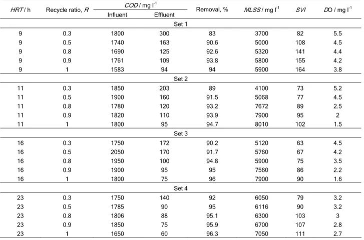
Table 3. The details of experimental runs
COD / mg l-1
HRT / h Recycle ratio, R
Influent Effluent Removal, % MLSS / mg l
-1
SVI DO / mg l-1
Set 1
9 0.3 1800 300 83 3700 82 5.5
9 0.5 1740 163 90.6 5000 108 4.5
9 0.8 1690 125 92.6 5320 141 4.4
9 0.9 1761 109 93.8 5800 155 4.2
9 1 1583 94 94 5900 164 3.8
Set 2
11 0.3 1850 203 89 4100 73 5.2
11 0.5 1900 160 91.5 5068 77 4.5
11 0.8 1780 120 93.2 7672 89 2.5
11 0.9 1820 110 93.9 7900 95 2
11 1 1800 95 94.7 8010 102 1.5
Set 3
16 0.3 1750 172 90.2 5120 63 4.5
16 0.5 2050 170 91.7 5760 67 4.2
16 0.8 1950 100 94.8 5900 75 3.5
16 0.9 1900 95 95 7560 86 2.2
16 1 1800 75 96 7900 90 1.6
Set 4
23 0.3 1750 140 92 6050 79 3.2
23 0.5 1785 90 95 6116 90 3.2
23 0.8 1806 88 95.1 6300 103 3
23 0.9 1850 75 95.9 6700 107 2.8
SVI = MLSS
V 1000
(4)
where the variable V stands for the volume of the
sludge settled during 30 min in a 1000 ml of Imhoff
cone (ml); the S0 is influent concentration of the
pol-lutant (mg l-1) and MLVSS is the mixed liquor
sus-pended solid in an aeration tank (mg l-1). The specific
substrate utilization rate (mg COD mg-1 X d-1) is
ex-pressed in the following equation:
X S S U
H 0
θ
−
= (5)
where the variable θH stands for the hydraulic
reten-tion time (HRT, d) and X is the biomass concentration
or it may represent(s) the mixed liquor volatile
suspended solids (MLVSS, mg l-1). To make the data
fit in to the linear equation, the double reciprocal form of the specific growth is written by the following equation [5]:
k kS
k U
1 1
e s +
= (6)
where the Se is the effluent concentration of the
pollutant (mg l-1); ks is the saturation constant for COD
removal (mg l-1) and k is the maximum specific rate
constant for COD removal (d-1). The sludge retention
time is expressed as a function of the process yield, as shown in Equ. (7):
d
1
k Yu
SRT = − (7)
where Y is the maximum growth yield coefficient (g X
g−1 S) and kd is the death rate constant (d−1). This
equation is applied either in recycle or for the system of non-recycled aeration tank [12,13].
Feed samples and the filtered effluent from the
clarifier were collected for analytical purposes. The COD
of the collected samples was analyzed by the closed reflux method. The cell optical density and the cell dry weights were measured for the biomass concen-trations. All the analyses were based on standard methods for the examination of wastewater [29].
RESULTS AND DISCUSSION
The activated sludge system was implemented for the removal of organic pollutants from the influents of Amol Industrial Park. The wastewater used for the present research, was obtained from the plant’s inlet wastewater. Kinetic parameters for the activated sludge process and the sludge recycle ratio with respect to
HRT were obtained. The COD removal, DO and SVI
were experimented for the designed experimental aeration basin.
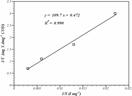
A linear model fitted for the experimental data obtained by the activated sludge system implemented for the Amol's Industrial Park influents (Figure 2). The double reciprocal plot for the specific growth and or-ganic pollutants are perfectly fitted according to the
expression stated in Eq. (6). The HRT was in the range
of 8 to 28 h and SRT was set at 10 d. From the slope
and the intercept of the best fitted line, the rate con-stant and the Monod concon-stant were found to be 2.12
d-1 and 232.4 mg l-1, respectively. The large values of
ks shows that either the biomass grown on the was-tewater has low affinity for the substrate or that the rate expression can be simplified and may lead to the first order [28]. To determine the optimum value,
charts of COD removal values versus HRT values
and SVI values versus HRT values were depicted.
177 Similarly, the experimental data obtained with
variable SRT in the range of 5 to 30 d at constant
HRT (12 h) were plotted in form of 1/θc versus U
according to Eq. (7) and the following constants were determined from the slope and the intercept of the
best fitted line (Figure 3). The yield, Y, was defined
(0.33 gX g-1 S) and the decay coefficient was 0.096
d−1. The kinetic parameters for the domestic
waste-water were experimented [28]. The results showed
that the ks, k, Y and kd were 85.5 mg/l, 1.71 d-1, 52 %
and 0.06 d-1, respectively [15].
The kinetic and stoichiometric constants deter-mined for this wastewater are comparable with the
literature reports where k is between 1 and 5 d−1, k
s is
100–300 mg\l−1, Y is 0.2–0.5 g X g−1 S and kd is 0.01–
-0.15 d−1 [22].
Figure 4 shows the percentage of the COD
re-moval with respect to HRT while the sludge recycle
ratio varied from 0.3 to 1.1. The maximum percentage
of the COD removal was obtained while the value of
HRT was 1.1. As the sludge recycle ratio was
increa-sed from 0.3 to 1.1, the COD removal was improved
by 12 %.
Figure 3. Plot of 1/SRT vs. U for variable SRT experiments.
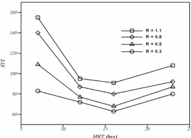
Figure 5 shows the effect of HRT on SVI values. The sludge index was gradually decreased with
res-pect to HRT. The SVI was minimized with HRT at 16 h.
Figure 6 shows that the COD removal was
ba-sed on the sludge recycle ratio. As the recycle ratio
increased gradually the percentage of the COD
remo-val was increased. While collecting the above data,
the HRT was fixed at 16 h.
Figure 7 presents the sludge volume index (SVI)
with respect to the sludge recycle ratio. The SVI
in-creased with gradually increase of the recycle ratio. At high value of the sludge recycle ratio, the retained
sludge in the aeration basin was also higher. The SVI
value higher than 200 and the return sludge concen-tration lower than 8000 mg/l is a sign of the poor set-tle ability of the sludge and may cause bulking in cla-rifier [14].
Figure 5. The effect of the HRT increase on SVI values at averaged COD, 27 °C, 30 l aerated vessel.
Figure 6. The effect of the sludge recycle ratio on COD removal at averaged COD, 27 °C C, 30 l aerated vessel.
179 The performance of the activated sludge
pro-cess is limited by the availability of oxygen [12,13].
Another parameter which was discussed is the DO
level during the experiment and its depletion by in-creasing the recycle ratio. It should be considered that the power of the diffuser was constant during the experiments. Figure 8 presents the concentration of
dissolved oxygen (DO) with respect to the sludge
re-cycle ratio. As the rere-cycle ratio increased, the DO
concentration gradually decreased. At the low value
of the recycle ratio, of about 0.3, the DO level was
about 4.5 mg l-1 as the recycle ratio increased to 1.2,
the DO value dropped to about 2 mg l-1. In an
additi-onal investigation at the same site, it was found out that by adding urea and phosphate to the aerobic tank, there was a 5 % increase in the total removal efficiency [4].
Figure 8. The effect of the sludge recycle ratio on DO level in aeration tank at averaged COD, 27 °C, 30 l aerated vessel.
CONCLUSION
The effects of HRT and the sludge recycle ratio
were studied as a parameter affected the removal
ef-ficiency of COD and SVI value in an aerobic activated
sludge system. The HRT values beyond 16 h had no
significant effect on the COD removal efficiency. At
HRT of 16 h the minimum value of SVI was obtained.
The same results were also achieved for the sludge
recycle ratio. The COD removal was increased with
an increase of the recycled sludge ratio.
The SVI values were increased by increasing
the recycle sludge. And it may reach 100 which could cause the bulking effects of the sludge. To avoid such
phenomena the SVI was minimized.
DO depletion may cause a problem during the
increase of the sludge recycling. But at the recycle
ratio of 0.75, DO was obtained as 3 mg l-1, which was
suitable for the activated sludge process.
Acknowledgements
The work was made possible thanks to the sup-port of Biotechnology Research Center, Noushirvani, Babol University of Technology, Babol, Iran. The au-thors wish to acknowledge the staff member in Amol Industrial Park Treatment Plant for their cooperation.
Nomenclature
Q - Flow rate, l/d
V - Working volume of the aerated vessel, l
S0 - Initial substrate, mg l-1
S - Final substrate, mg l-1
τ - Hydraulic retention time, d
K - Rate constant, d-1
Ks - Monod constant, mg l-1
E - Treatment efficiency, %
X - Biomass concentration, mg l-1
F/M - Food to microbe ratio, dimensionless
Y - Biomass yield, dimensionless
U - Substrate utilization rate, d-1
θc - Mean cell residence time, d
Kd - endogenous decay coefficient, d-1.
REFERENCES
[1] J. S. Arceivala, Wastewater treatment for pollution control, 2nd Ed., Tata McGraw-Hill Publishing Co., New Delhi, 1998
[3] G. Najafpour , H. A. Yieng, H. Younesi, A. Zinatizadeh, Proc. Biochem. 40 (2005) 2879
[4] G. D. Najafpour, B. Hosseini, M. Sadeghpoor, M. Norouzi, The 5th International Chemical Engineering
Congress, Jan. Kish Island, Iran, 2008
[5] Metcalf and Eddy, Wastewater engineering, Treatment and reuse, 4th Ed., McGraw Hill, New York, 2003
[6] J. E. Burgess, J. Quarmby, Biotechnol. Adv. 17 (1999) 49 [7] H. J. H. Elissen, T. L. G. Hendrick, H. Temmink, C. J. N.
Buisman, Wat. Res. 40 (2006) 3713
[8] G. A. Ekama, S. W. Sotemann, M. C. Wentzel, Wat. Sear. 41 (2007) 244
[9] B. P. McNicholla, J. W. McGrathb, J. P. Quinnb, Wat. Res. 41 (2007) 127
[10] N. Ricq, S. Barbati, M. Ambrosio, Analysis 28 (2001) 872 [11] F. Gebara, Wat. Res. 33 (1999) 230
[12] J. Eckenfelder, W. W. Industrial water pollution control, 3rd Ed., McGraw Hill, New York, 2000
[13] R. L. Droste, Theory and practice of water and waste-water treatment, Wiley, New York, 1997
[14] M. Richard, S. Brown, F. Collins, 20th Annual USEPA National operator Trainers Conference, Buffalo, NY, 2003 [15] G. Najafpour, M. Sadeghpour, A. L. Zinatizadeh, CI&CEQ
J. 14 (2007) 211
[16] G. W. Chen, H. Q. Yu, P. G. Xi, Biores. Technol. 98 (2006) 729
[17] M. Bernhard, J. Muller, T. P. Knepper, Wat. Res. 40 (2006) 3419
[18] J. S. Huang, H. H. Chou, C. M. Chen, C. M. Chiang, Chemosphere 68 (2007) 382
[19] W. C. Chang, C. F. Ouyang, W. L. Chiang, C. W. Hou, Wat. Res. 32 (1998) 727
[20] K. Vijayaraghavan, A. Desa, B. A. M. Ezani, Environ. Manag. J. 82 (2007) 24
[21] M. Fouad, R. Bhargava, Environ. Manag. J. 74 (2005) 245 [22] P. M. Yunus, F. Kargi, Hazard. Mater. J. 147 (2007) 372 [23] G. D. Najafpour, A. A. L. Zinatizadeh, L. K. Lee, Biochem.
Eng. J. 30 (2006) 297
[24] N. M. Chong, T. Y. Lin, Biores. Technol. 98 (2007) 1124 [25] G. D. Najafpour, A. A. L. Zinatizadeh, A. R. Mohamed, M.
H. Isa, H. Nasrollahzadeh, Proc. Biochem. 41 (2006) 370 [26] Y. T. Kang, Y. H. Cho, E. H. Chung, Desalination 202
(2007) 68
[27] C. Bougrier, J. P. Delgenes, H. Carrere, Biochem. Eng. J. 34 (2007) 20
[28] G. D. Najafpour, Biochemical engineering and biotech-nology, Elsevier, Amsterdam, 2007