GID
2, 429–455, 2012E-sail mass model
P. Janhunen et al.
Title Page
Abstract Introduction
Conclusions References
Tables Figures
◭ ◮
◭ ◮
Back Close
Full Screen / Esc
Printer-friendly Version Interactive Discussion
Discussion
P
a
per
|
Dis
cussion
P
a
per
|
Discussion
P
a
per
|
Discussio
n
P
a
per
|
Geosci. Instrum. Method. Data Syst. Discuss., 2, 429–455, 2012 www.geosci-instrum-method-data-syst-discuss.net/2/429/2012/ doi:10.5194/gid-2-429-2012
© Author(s) 2012. CC Attribution 3.0 License.
Geoscientiic
Instrumentation Methods and Data Systems
Discussions
This discussion paper is/has been under review for the journal Geoscientific Instrumentation, Methods and Data Systems (GI). Please refer to the corresponding final paper in GI if available.
Electric solar wind sail mass budget
model
P. Janhunen1, A. A. Quarta2, and G. Mengali2 1
Finnish Meteorological Institute, Helsinki, Finland
2
Department of Aerospace Engineering, University of Pisa, Pisa, Italy
Received: 24 May 2012 – Accepted: 18 June 2012 – Published: 10 July 2012 Correspondence to: P. Janhunen ([email protected])
GID
2, 429–455, 2012E-sail mass model
P. Janhunen et al.
Title Page
Abstract Introduction
Conclusions References
Tables Figures
◭ ◮
◭ ◮
Back Close
Full Screen / Esc
Printer-friendly Version Interactive Discussion
Discussion
P
a
per
|
Dis
cussion
P
a
per
|
Discussion
P
a
per
|
Discussio
n
P
a
per
|
Abstract
The electric solar wind sail (E-sail) is a new type of propellantless propulsion system for Solar System transportation, which uses the natural solar wind for producing space-craft propulsion. This paper discusses a mass breakdown and a performance model for an E-sail spacecraft that hosts a scientific payload of prescribed mass. In particular,
5
the model is able to estimate the total spacecraft mass and its propulsive accelera-tion as a funcaccelera-tion of various design parameters such as the tethers number and their length. A number of subsystem masses are calculated assuming existing or near-term E-sail technology. In light of the obtained performance estimates, an E-sail represents a promising propulsion system for a variety of transportation needs in the Solar System.
10
1 Introduction
The electric solar wind sail (E-sail) is an innovative deep space propulsion concept that uses the solar wind dynamic pressure for generating thrust without the need of reaction mass (Janhunen, 2006, 2009; Janhunen et al., 2010). The E-sail spacecraft is spun around its symmetry axis and uses the centrifugal force to deploy and stretch
15
out a number of thin, long and conducting tethers, which are kept in a high positive potential by an onboard electron gun (Janhunen et al., 2010). The latter compensates the electron current gathered by the conducting tethers from the surrounding solar wind plasma.
A baseline, full-scale, E-sail propulsion system comprises 2000 km of total main
20
tether length (for example 100 tethers, each one being 20 km long), with 25 kV tether voltage, 960 W electron gun power consumption and 1.16 N nominal thrust at 1 AU
from the Sun. If the main tethers are sufficiently long such that the potential sheath
overlapping between them is negligible, the propulsive thrust varies as 1/r, wherer is
the Sun-spacecraft distance. Note, for comparison, that in the classical photonic solar
25
GID
2, 429–455, 2012E-sail mass model
P. Janhunen et al.
Title Page
Abstract Introduction
Conclusions References
Tables Figures
◭ ◮
◭ ◮
Back Close
Full Screen / Esc
Printer-friendly Version Interactive Discussion
Discussion
P
a
per
|
Dis
cussion
P
a
per
|
Discussion
P
a
per
|
Discussio
n
P
a
per
|
is, as 1/r2) with the solar distance. Therefore the E-sail concept is especially attractive for a mission towards the outer Solar System, such as a Jupiter rendezvous (Quarta et al., 2011) or a mission towards the Heliopause (Quarta and Mengali, 2010) and the Solar System boundaries.
The E-sail propulsive thrust per unit length (of a main tether) is expectedly about
5
580 nN m−1 so that, for example, a 20 km long tether gathers about 11.6 mN of thrust
from the surrounding solar wind plasma. The previous thrust estimate at 1 AU corre-sponds to an average solar wind. Actually the solar wind properties vary widely along
basically all relevant timescales. However, due to certain plasma physical effects, the
E-sail propulsive thrust tends to vary much less than the solar wind dynamic pressure
10
when a simple constant power strategy is applied to adjusting the tether voltage in response to solar wind density variations (Toivanen and Janhunen, 2009).
The main tethers are spun so that the centrifugal force overcomes the propulsive thrust by a factor of about 5. Accordingly, each main tether has to withstand about 5 cN continuous pull force without breaking. In addition, the main tethers must survive the
15
micro-meteoroid impacts along the mission lifetime (Hoyt and Forward, 2000), whose
maximum reference value is about ten years. These requirements are filled with suffi
-cient margin by a four-line Heytether (Sepp ¨anen et al, 2011), produced by ultrasonic bonding from 25 µm and 50 µm aluminium wires (Kurppa et al., 2010).
Assuming ten years of flight time with full thrust of 1 N, an E-sail propulsion system
20
produces a total impulse of about 300 MNs. This value is equivalent to the total impulse produced by a high-thrust propulsion system, for example a chemical rocket with a spe-cific impulse of 300 s burning 100 t of propellant, or an electric thruster with a spespe-cific impulse of 3000 s that uses 10 t of propellant.
The propulsive acceleration and the corresponding mission performance in terms of
25
GID
2, 429–455, 2012E-sail mass model
P. Janhunen et al.
Title Page
Abstract Introduction
Conclusions References
Tables Figures
◭ ◮
◭ ◮
Back Close
Full Screen / Esc
Printer-friendly Version Interactive Discussion
Discussion
P
a
per
|
Dis
cussion
P
a
per
|
Discussion
P
a
per
|
Discussio
n
P
a
per
|
paper is to develop such a parametric model using near-term technology data. The new mathematical model deepens and updates the previous simplified approach of Mengali et al. (2008).
2 Scalable E-sail mathematical model
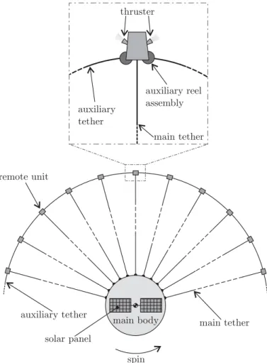
Consider an E-sail propulsion system, constituted by a main body andN main tethers,
5
each one having lengthL. A Remote Unit (RU) is placed at the tip of each tether, see
Fig. 1. Every RU comprises two reels for deploying an auxiliary tether, as discussed next, and a thruster unit for controlling the main tether’s angular velocity.
The total spacecraft mass can be thought of as being the sum of the following
con-tributions: (1) scientific payload of mass mpay, (2) high voltage subsystem including
10
electron guns, (3)N main tethers of massmmt,N main tether reels of mass mmr, and
N RUs of mass mru, (4) auxiliary tether of mass mat, (5) tether cameras and E-sail
controller, (6) power system with solar panels, (7) telemetry system with antennas, (8) thermal control subsystem, (9) attitude control system (ACS), and (10) structural
massmstr. The simplified expression for the total spacecraft massmis thus
15
m=ηmamb+N(mmt+mru)+mat
(1−ηstr) (1−ηacs) (1)
where the dimensionless coefficientηma=1.2 is introduced to account for a 20 %
mar-gin on the actual value, whileηacsmodels the fact that the ACS mass is a given fraction of the spacecraft’s total mass.
Each term in the numerator of the right hand side of Eq. (1) can be expressed as
20
a function of the system’s parameters, as is better discussed later. Also, the termmb
indicates the mass of the functional components of the main body of the spacecraft, which is assumed to be in the form
mb =
mgc+mvs+ncamca+negmeg+msa+ mpay
1−ηtms +N mmr
GID
2, 429–455, 2012E-sail mass model
P. Janhunen et al.
Title Page
Abstract Introduction
Conclusions References
Tables Figures
◭ ◮
◭ ◮
Back Close
Full Screen / Esc
Printer-friendly Version Interactive Discussion
Discussion
P
a
per
|
Dis
cussion
P
a
per
|
Discussion
P
a
per
|
Discussio
n
P
a
per
|
whose new symbols are explained in the next subsections.
2.1 High voltage subsystem
We assume neg=3 redundant electron guns, each one providing a beam power Peg
and having massmeg=γegPeg, where the gun specific mass isγeg=1.0 kg kW−1. The
electric power Peg varies with the distance r from the Sun and can be related to the
5
total length NL of the main tethers through a linear power density β, whose value
essentially depends (Mengali et al., 2008) on the main tethers voltage and on the Heytether (Sepp ¨anen et al, 2011) total surface area. In particular, using the current Heytether configuration, the expression for the linear power density is
β=2n⊕
v u u t2e
3V3 0 me
R1+(3π/2)R2
(3)
10
whereV0 is the nominal voltage of the main tethers,n⊕=7.6×10⁶m−3 is the nominal
solar wind density at r=r⊕,1 AU, e is the electron charge, and m
e is the electron
mass. For example, assumingV0=25
,kV and the previous tether dimensions (R1=25 µm andR2=12.5 µm), Eq. (3) provides
a linear power densityβ≃0.4790 W km−1.
15
Taking into account a reference condition that corresponds to the minimum Sun-spacecraft distancermin=0.9 AU, a conservative estimate of the electric power required
by the electron gun is
Peg =N L β r⊕/rmin2
. (4)
Even though the solar wind densitynexhibits large natural variations, a simple strategy
20
of varying the tether voltageV away from the nominalV0, such thatPeg is constant, is quite effective for maintaining constant the daily, weekly or monthly averaged thrust at
GID
2, 429–455, 2012E-sail mass model
P. Janhunen et al.
Title Page
Abstract Introduction
Conclusions References
Tables Figures
◭ ◮
◭ ◮
Back Close
Full Screen / Esc
Printer-friendly Version Interactive Discussion
Discussion
P
a
per
|
Dis
cussion
P
a
per
|
Discussion
P
a
per
|
Discussio
n
P
a
per
|
Two plasma physical effects are responsible for this at first surprising behavior. The first one is that the thrust is proportional to the total tether length times the tether’s electron sheath width. For a fixed voltage the latter is proportional to the solar wind
plasma Debye length, which, in turn, is proportional to 1/√n. As a result (Janhunen,
2009) the thrust is approximately linearly proportional to the tether voltage V, but it
5
has only a square root dependence on the solar wind dynamic pressurePdyn=mpn v2
wherev is the solar wind speed andmpis the proton mass. The second effect is that,
because the tether current is proportional ton√V,V must be varied asn−2/3in order to
maintainPeg constant. When combined, these two effects imply that under a constant
Peg strategy the thrust is proportional to n1/6v, i.e. the thrust depends only weakly
10
on the solar wind density. Furthermore, solar wind variations ofn and v are typically
anticorrelated, and this tends to further reduce the thrust fluctuations.
There are several ways on how high voltage distribution (and grounding plan) can be obtained. One way is to have a relatively low energy (e.g. 1 kV) electron gun connected to a common internal bus that maintains the electron gun at its voltage. Each tether
15
can then have its own small high voltage source, thus allowing an arbitrary differential modulation of tether voltages and no need for high voltage switches, resistors,
po-tentiometers or cables. The high voltage source mass is assumed to bemvs=γvsPeg,
whereγvs=20 kg kW−1is the specific mass of the high voltage generator. For example,
Ultravolt makes 30 W kV−1 vacuum compatible DC voltage source model 35A24-P30
20
with aγvs of 14.2 kg kW−1 and an efficiency of 70 %. Therefore a value of 20 kg kW−1
seems to be a reasonable value, even though it may require some customization effort.
2.2 Main tethers
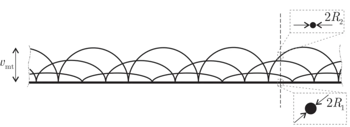
The main tether is a four-wire aluminium (density ρAl=2700 kg m−3) Heytether
(Sepp ¨anen et al, 2011), composed of a (straight) base wire of radiusR1=25 µm, and
25
three (approximately semicircular) loop wires of radiusR2=12.5 µm, the latter being
GID
2, 429–455, 2012E-sail mass model
P. Janhunen et al.
Title Page
Abstract Introduction
Conclusions References
Tables Figures
◭ ◮
◭ ◮
Back Close
Full Screen / Esc
Printer-friendly Version Interactive Discussion
Discussion
P
a
per
|
Dis
cussion
P
a
per
|
Discussion
P
a
per
|
Discussio
n
P
a
per
|
The mass per unit length of the main tether isλmt=ρAlπ
h
R12+(3π/2)R22i ≃1.155×
10−5kg m−1. Therefore, the tether mass mmt depends linearly on L according to the
simple relationship
mmt =λmtL. (5)
2.3 Main tether reel assembly
5
The main tether reel assembly is a motorized mechanism that holds the reeled tether inside, and deploys it in orbit. Its mass is estimated to be
mmr =mmr0+ρmr Vmt
ηmr (6)
wheremmr0=0.1 kg corresponds to the mass of the motorized reel assembly in case
of a short tether such as that used in ESTCube-1 and Aalto-1 CubeSat missions,
10
ρmr=500 kg m−3 is the assumed mass density of the reel structure with respect to
its contained volume,Vmt=mmt/ρAl is the solid aluminium volume of the main tether
andηmr=0.3 is the packaging factor of the reeled tether.
2.4 Auxiliary tether
The auxiliary tether is manufactured using Kapton (with a density ρKa=1420 kg m−3)
15
and is used to connect the RUs for avoiding collisions between adjacent tethers (Janhunen et al., 2010). Assuming that the auxiliary tether is constituted by a
rect-angular section of height hat=12.7 µm and width wat=3 cm, its linear density is
λat=ηpρKahatwat=2.705×10⁻⁴kg m−1 whereηp=0.5 is a dimensionless coefficient that models the perforation of the auxiliary tether’s stripe required to produce a proper
20
amount of elasticity. The length of the auxiliary tether is approximately equal to the length of a circumference of radiusL. The total auxiliary tether mass is thus
GID
2, 429–455, 2012E-sail mass model
P. Janhunen et al.
Title Page
Abstract Introduction
Conclusions References
Tables Figures
◭ ◮
◭ ◮
Back Close
Full Screen / Esc
Printer-friendly Version Interactive Discussion
Discussion
P
a
per
|
Dis
cussion
P
a
per
|
Discussion
P
a
per
|
Discussio
n
P
a
per
|
2.5 Remote units
Each RU hosts a thruster for initiating and (possibly later) controlling the tether rig’s spin. It also includes the reels from which the auxiliary tethers are deployed. Two thruster options are being considered in more detail, a cold gas thruster of Nanospace and an ionic liquid FEEP thruster of Alta (Marcuccio et al., 2011). The cold gas thruster
5
can produce a total impulse sufficient for the required initial spin and for the small spin rate adjustments during flight operations. The FEEP thruster, on the other hand, has a total impulse capability sufficient for controlling the spin to counteract the Coriolis ac-celeration that results from orbiting around the Sun with an inclined sail (Toivanen and Janhunen, 2012).
10
Prototypes of cold gas thruster and FEEP thruster as RU’s subsystems have been
designed at ˚Angstr ¨om Space Technology Centre. The wet mass of a FEEP-unit is
0.880 kg, whose auxiliary tether reel system’s share is 0.135 kg. The mass of the ionic liquid propellant is 0.07 kg and the total impulse capability 2000 Ns. The wet mass of a cold gas-unit is 0.613 kg, of which 0.05 kg is propellant, and the total impulse capability
15
is 40 Ns.
For conservative purposes, here we assume that each RU contains a FEEP thruster that is mounted either along the spin accelerating direction or along the decelerating direction, see Fig. 1. Therefore there are two subtypes of RUs, which are otherwise identical except being mirror images of each other in the left-right direction. In a
base-20
line configuration, accelerating and braking thrusters are alternated on adjacent RUs. More general arrangements could also be considered in specific missions. Accordingly, the RU’s mass with a FEEP unit is parameterized as
mru =mru0 + mat
ρKaρar (8)
GID
2, 429–455, 2012E-sail mass model
P. Janhunen et al.
Title Page
Abstract Introduction
Conclusions References
Tables Figures
◭ ◮
◭ ◮
Back Close
Full Screen / Esc
Printer-friendly Version Interactive Discussion
Discussion
P
a
per
|
Dis
cussion
P
a
per
|
Discussion
P
a
per
|
Discussio
n
P
a
per
|
2.6 Tether cameras and controller
To find out the actual position of each RU at the main tether tips, a numbernca=12
of cameras along the perimeter of the main spacecraft are used. Each camera has
massmca=0.04 kg (Pappa et al., 2004). Each RU has an optical beacon transmitting
a unique optical coding so that the unit can be identified by the cameras. The E-sail
5
also needs a guidance computer to which a massmgc=1 kg is allocated, including the
radiation shielding. Since the tether rig moves slowly, a moderate amount of computing power is sufficient.
2.7 Power generation subsystem
The power generation subsystem includes solar panels with their deployment
mecha-10
nism as well as a power processing unit that produces bus voltage and, very likely, a battery pack.
For a baseline deep space mission, where the Sun-spacecraft distance ranges be-tween about 0.9 AU and 4 AU, rather large solar panels are typically needed to provide
the scientific payload with a sufficient power up to the aphelion radius. It is assumed
15
that during the cruise phase both payload and telemetry instruments are in idle (or
keep-alive) mode, with a specific power consumption of 0.1 W kg−1, while during the
operating mode (that is, when the E-sail is turned off) the power consumption is about
1 W kg−1. For conservative purposes, we assume that the E-sail could also use 10 W
of base power in addition to the electron gun requirement, even when it is turned off.
20
Note that the electric power required by the electron gun varies with the solar distance as 1/r2, that is, in the same way as the illumination of the solar panels.
For science payloads sizing, the power system is always constrained by the payload requirements at 4 AU (aphelion distance), and not by the E-sail requirements during
the cruise phase. Hence the power system has to provide 1 W kg−1 for the payload
25
GID
2, 429–455, 2012E-sail mass model
P. Janhunen et al.
Title Page
Abstract Introduction
Conclusions References
Tables Figures
◭ ◮
◭ ◮
Back Close
Full Screen / Esc
Printer-friendly Version Interactive Discussion
Discussion
P
a
per
|
Dis
cussion
P
a
per
|
Discussion
P
a
per
|
Discussio
n
P
a
per
|
assume a specific mass value ofγsa=10 kg kW−1for the power subsystem as a whole,
when the reference kW-value is the full power gathered at 0.9 AU. This is motivated by the fact that the full panel power at 0.9 AU does not need to be processed by the power processing unit. It has only to provide enough power to the payloads and to guarantee the solar panels health. We also assume an end of life solar panel degradation factor
5
ofηsa=1.2.
Accordingly, the power system produced by the solar panels atrmax=4 AU is
Psarmax =ηsa
Po+max
ηvsPeg
r
min rmax
2+ηkaPpay,Ppay
(9)
wherePpay=mpay/γpay is the payload required power,ηka=0.1 is the idle versus duty
power ratio of both the payload and the telemetry systems, andηvs=1.25 is the
as-10
sumed overhead factor (reciprocal of the efficiency) of the HV source.
2.8 Telemetry, ACS, thermal and structure
We assume that the telemetry subsystem mass is related to the scientific payload such
that the telemetry subsystem plus payload mass is given bympay/(1−ηtms), where the
telemetry mass fraction isηtms=0.2. This choice is qualitatively motivated by the fact
15
that each scientific instrument generates data that must be transmitted by the telemetry system. If a payload needs more telemetry capability than is assumed here, one has to reserve extra mass for it from the scientific payload budget. Our results concerning the E-sail mass fraction are not sensitive to the previous parametric choice.
The E-sail requires a service from satellite’s attitude control system (ACS) for
point-20
ing the spin axis towards the Sun and starting the spin motion at the beginning of E-sail deployment. Most of required angular momentum is obtained from RU thrusters, but a small fraction is gotten from the ACS. If the mission calls for accurate manoeuvring near an asteroid or another small body, a micro-propulsion system is needed for over-coming a small photonic sail effect of the tethers and for fine orbit control. We assume
GID
2, 429–455, 2012E-sail mass model
P. Janhunen et al.
Title Page
Abstract Introduction
Conclusions References
Tables Figures
◭ ◮
◭ ◮
Back Close
Full Screen / Esc
Printer-friendly Version Interactive Discussion
Discussion
P
a
per
|
Dis
cussion
P
a
per
|
Discussion
P
a
per
|
Discussio
n
P
a
per
|
that the attitude and orbit control system (AOCS) mass is a fractionηacs=0.05 of the
spacecraft’s total mass.
Similarly, the thermal control subsystem massmtcsis expressed as a given
percent-age of the main body mass through the coefficient ηtcs=0.05. Finally, the structural
parts of the main spacecraft including RU launch locks is, by assumption, a fraction
5
ηstr=0.15 of the total mass. The main spacecraft parameters of the mass model are
collected in Table 1.
2.9 Characteristic acceleration
Using Table 1 the total spacecraft mass given by Eq. (1) can be computed in terms of four design parameters, namely (N,L,V0,mpay).
10
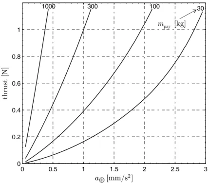
The spacecraft characteristic acceleration, that is, the maximum propulsive
acceler-ation at a reference distancer⊕ from the Sun, can be similarly expressed as a function
of the same four parameters. In fact, the thrust per unit main-tether-length at a distance of 1 AU from the Sun is (Janhunen et al., 2010)
f =fVV0−f0 (10)
15
wheref0,24.16 nN m−1andfV ,24.16 nN m−1kV−1. The spacecraft characteristic
ac-celeration is therefore
a⊕ = f N Lm . (11)
3 Results
Tables 2, 3 and 4 show the spacecraft mass budget and some other fundamental
pa-20
GID
2, 429–455, 2012E-sail mass model
P. Janhunen et al.
Title Page
Abstract Introduction
Conclusions References
Tables Figures
◭ ◮
◭ ◮
Back Close
Full Screen / Esc
Printer-friendly Version Interactive Discussion
Discussion
P
a
per
|
Dis
cussion
P
a
per
|
Discussion
P
a
per
|
Discussio
n
P
a
per
|
adjusted for each N until the desired characteristic acceleration was obtained. Note
that the tether length was restricted to a maximum value of 20 km and the number of tethers to 100. The “Total without E-sail” values were obtained by using the same mass
formula, but enforcing the conditionsN=0 andL=0. This represents a spacecraft with
same payload mass and other functionalities, but without on-orbit propulsive
capabili-5
ties. The E-sail mass fraction is the effective mass divided by the total spacecraft mass, and the E-sail specific acceleration is the propulsive thrust at 1 AU divided by its eff ec-tive mass. Tables 2, 3 and 4 show some characteristic trends that can be summarized as follows.
1. When the E-sail size increases, its specific acceleration improves and the E-sail
10
mass fraction decreases. This is because the main tether reels and RUs have, by assumption, a certain base mass even in the limit of short main and auxiliary tethers. By redesigning and miniaturizing these items, the E-sail specific accel-eration could probably be improved for small sizes. On the other hand, the trend would probably not continue to even larger sizes, because for tethers longer than
15
20–30 km, their tensile strength requirement would start to grow beyond what Heytethers tolerate. If even longer tethers were used, thicker wires or better ma-terials should probably be employed.
2. Tables 2 and 3 show that by moving from 0.1 mm s−2to 0.3 mm s−2of
characteris-tic acceleration, the E-sail’s mass fraction increases only slightly. For example, for
20
a 1000 kg of scientific payload, the spacecraft total mass is about 2535 kg when
a⊕=0.1 mm s−2, while it is 2596 kg (only 2.4 % larger) for a three times more
capable system (a⊕=0.3 mm s−2). In light of these numbers and assuming the
availability of E-sails of different sizes, using the lowest characteristic acceleration (a⊕=0.1 mm s−2) might be motivated only if the spacecraft payload is some bulk
25
material such as products from asteroid mining rather than a scientific payload.
GID
2, 429–455, 2012E-sail mass model
P. Janhunen et al.
Title Page
Abstract Introduction
Conclusions References
Tables Figures
◭ ◮
◭ ◮
Back Close
Full Screen / Esc
Printer-friendly Version Interactive Discussion
Discussion
P
a
per
|
Dis
cussion
P
a
per
|
Discussion
P
a
per
|
Discussio
n
P
a
per
|
For comparative purposes, Table 5 shows the mass breakdown for a spacecraft hav-ing the same parameters of Table 4 with the exception that in Table 5 the auxiliary tethers are made of 7.6 µm Kapton (instead of 12.7 µm) and that the cold gas thruster option is taken into account. Recall that the wet mass of the cold gas unit is 0.267 kg lighter than the FEEP version. The mass of a RU with cold gas thrusters can also be
5
representative of a solar photon blade equipped version of the RU, which has sufficient
spin rate control capability for any mission (Janhunen, 2012). Making the auxiliary teth-ers thinner favours longer tethteth-ers in the mass optimization process, while a reduced
RU base mass has the opposite effect. Because the numbers of tethers in Table 5 are
smaller than those in Table 4, a reduction of the auxiliary tether thickness has a larger
10
impact than that of changing the RU’s thruster class. For the 300 kg scientific payload case, the net result is a 28 % reduction in the E-sail effective mass and a corresponding increase in the E-sail specific acceleration.
We have assumed that the nominal tether voltageV0 (valid for average solar wind
conditions) has a fixed value of 25 kV throughout the paper. The maximum voltage for
15
which the hardware is designed should be larger, perhaps 40 kV, because otherwise the thrust would be decreased when the solar wind density is lower than its average
value (Toivanen and Janhunen, 2009). However, trading offthe hardware voltage limit
against other design parameters is outside the scope of this paper.
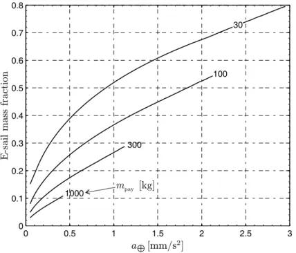
Figure 3 shows the E-sail mass fraction (effective E-sail mass divided by spacecraft
20
total mass) as a function of the characteristic acceleration, for different scientific
pay-loads:mpay={30, 100, 300, 1000}kg. For each payload mass, there exists a maximum
characteristic acceleration that can be reached by an E-sail. Recall that, by assump-tion, the E-sail performance is constrained by a maximum number (100) and length (20 km) of main tethers.
25
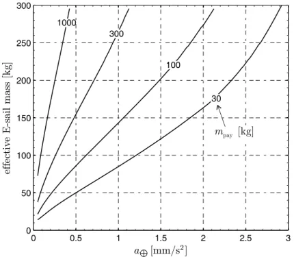
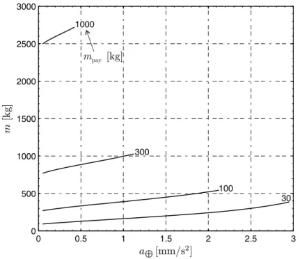
Figures 4–6 illustrate the corresponding effective E-sail mass, total spacecraft mass
GID
2, 429–455, 2012E-sail mass model
P. Janhunen et al.
Title Page
Abstract Introduction
Conclusions References
Tables Figures
◭ ◮
◭ ◮
Back Close
Full Screen / Esc
Printer-friendly Version Interactive Discussion
Discussion
P
a
per
|
Dis
cussion
P
a
per
|
Discussion
P
a
per
|
Discussio
n
P
a
per
|
applications. The upper limits of the level curve withmpay=30 kg correspond, instead,
to a high-performance E-sail for an advanced mission scenario as, for instance, a flyby
with outer planets or a Solar System escape. On the other side, the low a⊕ end of
level curve withmpay=1000 kg represents a case where 2.5 t spacecraft is moved at
0.1 mm s−2 characteristic accleeration (3 km s−1 of ∆v per year) by a moderate size
5
34-tether E-sail weighing 110 kg (Table 2). The latter case is consistent, for example, with an advanced exploration mission towards near-Earth asteroids, which involves an in-situ resource utilization and transportation (see Lewis, 1996 and Gerlach, 2005).
4 Conclusions
A detailed mathematical model has been developed for mass budget analysis and
per-10
formance evaluation of an E-sail spacecraft. Our aim was to estimate the component masses as realistically as possible with current or near-term technology while including a conservative 20 % overall mass margin.
Accurate mass estimates of a propulsion system are difficult to obtain, because the
thruster design has usually indirect effects on other spacecraft subsystems as, for
in-15
stance, the thermal and the attitude control systems. In this paper we have estimated
the effective E-sail mass by evaluating the mass difference between the actual and
a virtual spacecraft. The latter has the same functional components and satisfies the same environmental requirements of the former, but is wanting in the on-orbit propul-sive capabilities. In that way, the indirect mass contributions are included in the
estima-20
tion.
Numerical results show that the E-sail propulsion system, once qualified for flight, could be an interesting option for a wide class of deep space missions that include scientific payloads in the range 30–1000 kg, and require a characteristic acceleration
up to about 3 mm s−2. Moreover, as is shown in Table 5, some rather straightforward
25
near-term component level improvements have the potential of reducing the effective
GID
2, 429–455, 2012E-sail mass model
P. Janhunen et al.
Title Page
Abstract Introduction
Conclusions References
Tables Figures
◭ ◮
◭ ◮
Back Close
Full Screen / Esc
Printer-friendly Version Interactive Discussion
Discussion
P
a
per
|
Dis
cussion
P
a
per
|
Discussion
P
a
per
|
Discussio
n
P
a
per
|
performance. Future work will concentrate on prototyping and testing the E-sail subsys-tem as well as measuring the E-sail performance in small scale in the real environment, that is, within the solar wind.
Acknowledgements. This research was financed within the European Community’s Seventh Framework Programme (FP7/2007-2013) under grant agreement number 262733 and the 5
Academy of Finland grant decision 250591.
References
Gerlach, C. L.: Profitably exploiting near-Earth object resources, International Space De-velopment Conference, Washington, DC, available online: http://abundantplanet.org/files/ Space5-Ast-Profitably-Exploiting-NEO-Gerlach-2005.pdf (last access: 14 March 2012), 10
2005. 442
Hoyt, R. and Forward, R.: Alternate interconnection hoytether failure resistant multiline tether, U.S. Pat. 6286788, filed 8 September 2000. 431
Janhunen, P.: Electric sail for producing spacecraft propulsion, U.S. Pat. 7641151, accepted 2010, filed 2 March 2006. 430
15
Janhunen, P.: Increased electric sail thrust through removal of trapped shielding electrons by or-bit chaotisation due to spacecraft body, Ann. Geophys., 27, 3089–3100, doi:10.5194/angeo-27-3089-2009, 2009. 430, 434
Janhunen, P., Toivanen, P. K., Polkko, J., Merikallio, S., Salminen, P., Haeggstrom, E., Sepp ¨anen, H., Kurppa, R., Ukkonen, J., Kiprich, S., Thornell, G., Kratz, H., Richter, L., 20
Kr ¨omer, O., Rosta, R., Noorma, M., Envall, J., L ¨att, S., Mengali, G., Quarta, A. A., Koivisto, H., Tarvainen, O., Kalvas, T., Kauppinen, J., Nuottaj ¨arvi, A., and Obraztsov, A.: Elec-tric solar wind sail: Towards test missions, Rev. Sci. Instrum., 81, 111301-1–111301-11, doi:10.1063/1.3514548, 2010. 430, 435, 439
Janhunen, P.: Photonic spin control for solar wind electric sail, Acta Astronaut., in review, 2012. 25
441
GID
2, 429–455, 2012E-sail mass model
P. Janhunen et al.
Title Page
Abstract Introduction
Conclusions References
Tables Figures
◭ ◮
◭ ◮
Back Close
Full Screen / Esc
Printer-friendly Version Interactive Discussion
Discussion
P
a
per
|
Dis
cussion
P
a
per
|
Discussion
P
a
per
|
Discussio
n
P
a
per
|
Lewis, J. S.: Mining the sky: Untold riches from the asteroid, comets, and planets, Addison-Wesley, 1996. 442
Marcuccio, S., Giusti, N., and Pergola, P.: Development of a miniaturized electric propulsion sys-tem for the E-sail project, 62nd International Astronautical Congress, Paper IAC-11.B4.6A.3, 2011. 436
5
McInnes, C. R.: Solar sailing: Technology, dynamics and mission applications, Springer-Verlag, 46–54, 1999. 430
Mengali, G., Quarta, A. A., and Janhunen, P.: Electric sail performance analysis, J. Spacecraft Rockets, 45, 122–129, doi:10.2514/1.31769, 2008. 432, 433
Pappa, R. S., Blandino, J. R., Caldwell, D. W., Carroll, J. A., Jenkins, C. H. M., and Pollock, 10
T. C.: Optical diagnostic system for solar sails: Phase 1 final report, NASA/TM-2004-213511, NASA Langley Research Center, Hampton, Virginia, 2004. 437
Quarta, A. A. and Mengali, G.: Electric sail mission analysis for outer Solar System exploration, J. Guid. Control Dynam., 33, 740–755, doi:10.2514/1.47006, 2010. 431
Quarta, A. A., Mengali, G., and Janhunen, P.: Optimal interplanetary rendezvous com-15
bining electric sail and high thrust propulsion system, Acta Astronaut., 68, 603–621, doi:10.1016/j.actaastro.2010.01.024, 2011. 431
Sepp ¨anen, H., Kiprich, S., Kurppa, R., Janhunen, P. and Haeggstr ¨om, E.: Wire-to-wire bonding of µm-diameter aluminum wires for the Electric Solar Wind Sail, Microelectron. Eng., 88, 3267–3269, doi:10.1016/j.mee.2011.07.002, 2011. 431, 433, 434
20
Toivanen, P. K. and Janhunen, P.: Electric sailing under observed solar wind conditions, Astro-phys. Space Sci. Trans., 5, 61–69, doi:10.5194/astra-5-61-2009, 2009. 431, 433, 441 Toivanen, P. K. and Janhunen, P.: Spin plane control and thrust vectoring of electric solar wind
sail by tether potential modulation, J. Propul. Power, in review, 2012. 436
GID
2, 429–455, 2012E-sail mass model
P. Janhunen et al.
Title Page
Abstract Introduction
Conclusions References
Tables Figures
◭ ◮
◭ ◮
Back Close
Full Screen / Esc
Printer-friendly Version Interactive Discussion
Discussion
P
a
per
|
Dis
cussion
P
a
per
|
Discussion
P
a
per
|
Discussio
n
P
a
per
|
Table 1.Physical reference data.
parameter symbol value
Thrust/length/voltage f0 24.2 nN/(kV m) Nominal tether voltage V0 25 kV Thrust per length fV 24.2 nN m−
1
Aux. tether thickness hat 12.7 µm Main reel base mass mmr0 0.1 kg Tether camera mass mca 0.04 kg Number of tether cameras nca 12 E-sail computer mass mgc 1 kg FEEP Remote Unit base m. mru0 0.745 kg Number of electron guns neg 3 1 AU solar wind density n⊕ 7.6 cm−3 E-sail base power Po 10 W Heytether base wire radius R1 25 µm Heytether loop wire radius R2 12.5 µm Minimum solar distance rmin 0.9 AU Maximum solar distance rmax 4.0 AU Aux. tether width wat 3 cm Telemetry mass fraction ηtms 0.2 ACS mass fraction ηacs 0.05 Overall mass margin factor ηma 1.2 Main tether reel fill factor ηmr 0.3 Aux. tether perforation ηp 0.5 Solar panel EOL degrad. fac. ηsa 1.2 Structural fraction ηstr 0.15 Therm. sys. mass fraction ηtcs 0.05 HV source loss factor ηvs 1.25 Payload mass per power γpay 1000 kg kW−
1
E-gun mass per power γeg 1 kg kW− 1
Power system mass per power γsa 10 kg kW− 1
HV source mass per power γvs 20 kg kW− 1
Aluminium density ρAl 2700 kg m− 3
Kapton density ρKa 1420 kg m− 3
Aux. tether reel “density” ρar 282 kg m− 3
GID
2, 429–455, 2012E-sail mass model
P. Janhunen et al.
Title Page
Abstract Introduction
Conclusions References
Tables Figures
◭ ◮
◭ ◮
Back Close
Full Screen / Esc
Printer-friendly Version Interactive Discussion
Discussion
P
a
per
|
Dis
cussion
P
a
per
|
Discussion
P
a
per
|
Discussio
n
P
a
per
|
Table 2.Spacecraft mass budget and some other properties for a characteristic acceleration a⊕=,0.1 mms−2.
Scientific payloadmpay[kg] 100 200 500 1000
Number of tethersN 12 16 24 34
Tether lengthL[kg] 4.02 5.77 9.27 12.9 E-sail thrust at 1 AU [N] 0.03 0.05 0.13 0.25 E-sail powerPo+Peg[W] 38.5 64.6 142 269 Payload idle power [W] 12.5 25.0 62.5 125 Payload duty power [W] 125 250 625 1250 Main tethersN mmt[kg] 0.56 1.07 2.57 5.05
Main tether reelsN mmr[kg] 1.54 2.26 3.99 6.52
Electron guns 3meg[[kg] 0.09 0.16 0.39 0.78
HV sourcemvs[kg] 0.57 1.09 2.63 5.17 Cameras and computer [kg] 1.48 1.48 1.48 1.48 Remote unitsN mru[kg] 11.7 15.8 24.1 34.0
Auxtethers [kg] 6.83 9.80 15.8 21.9
Power systemmsa[kg] 32.0 61.6 151 299 Telemetry system [kg] 25.0 50.0 125 250 Thermal control [kg] 8.46 16.7 41.3 82.2
ACS [kg] 9.90 18.9 45.7 89.8
Structure [kg] 35.0 66.9 161 317
20 % margin [kg] 46.6 89.2 215 422
Total without E-sail [kg] 248 490 1215 2425 E-sail effective [kg] 31.7 45.1 74.1 110
Total [kg] 280 535 1290 2535
GID
2, 429–455, 2012E-sail mass model
P. Janhunen et al.
Title Page
Abstract Introduction
Conclusions References
Tables Figures
◭ ◮
◭ ◮
Back Close
Full Screen / Esc
Printer-friendly Version Interactive Discussion
Discussion
P
a
per
|
Dis
cussion
P
a
per
|
Discussion
P
a
per
|
Discussio
n
P
a
per
|
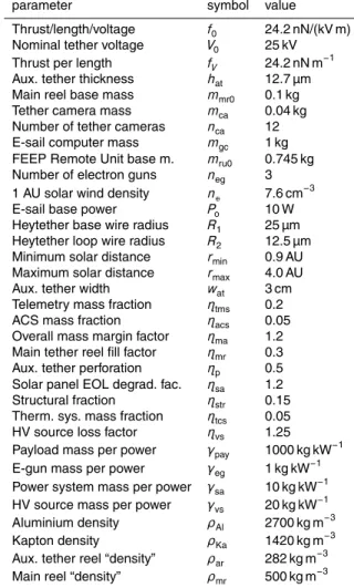
Table 3.Same as Table 2, but for a characteristic accelerationa⊕=0.3 mm s−2. Scientific payloadmpay[kg] 100 200 500 1000
Number of tethersN 16 24 36 50
Tether lengthL[km] 6.38 8.02 12.7 17.9 E-sail thrust at 1 AU [N] 0.06 0.11 0.27 0.52 E-sail powerPo+Peg[W] 70.3 124 281 540
Payload idle power [W] 12.5 25.0 62.5 125 Payload duty power [W] 125 250 625 1250 Main tethersN mmt[kg] 1.18 2.22 5.29 10.3 Main tether reelsN mmr[kg] 2.33 3.77 6.87 11.4 Electron guns 3meg[kg] 0.18 0.34 0.81 1.59
HV sourcemvs[kg] 1.21 2.28 5.42 10.6
Cameras and computer [kg] 1.48 1.48 1.48 1.48 Remote unitsN mru[kg] 16.2 23.3 35.4 49.3
Auxtethers [kg] 10.8 13.6 21.6 30.4
Power systemmsa[kg] 32.0 61.6 151 299 Telemetry system [kg] 25.0 50.0 125 250 Thermal control [kg] 8.54 16.8 41.6 82.8
ACS [kg] 10.5 19.8 47.1 91.9
Structure [kg] 37.0 69.7 166 324
20 % margin [kg] 49.3 93.0 221 433
Total without E-sail [kg] 248 490 1215 2425 E-sail effective [kg] 47.8 68.2 113 171
Total [kg] 296 558 1329 2596
GID
2, 429–455, 2012E-sail mass model
P. Janhunen et al.
Title Page
Abstract Introduction
Conclusions References
Tables Figures
◭ ◮
◭ ◮
Back Close
Full Screen / Esc
Printer-friendly Version Interactive Discussion
Discussion
P
a
per
|
Dis
cussion
P
a
per
|
Discussion
P
a
per
|
Discussio
n
P
a
per
|
Table 4.Same as Table 2, but for a characteristic accelerationa⊕=1 mm s−2. Scientific payloadmpay[kg] 100 200 300
Number of tethersN 44 62 86
Tether lengthL[km] 15.3 19.4 20.0 E-sail thrust at 1 AU [N] 0.39 0.70 1.00 E-sail powerPo+Peg[W] 409 720 1026 Payload idle power [W] 12.5 25.0 37.5 Payload duty power [W] 125 250 375 Main tethersN mmt[kg] 7.79 13.9 19.8 Main tether reelsN mmr [kg] 9.21 14.8 20.8
Electron guns 3meg[kg] 1.20 2.13 3.05
HV sourcemvs[kg] 7.98 14.2 20.3 Cameras and computer [kg] 1.48 1.48 1.48 Remote unitsN mru [kg] 43.1 59.3 77.6
Auxtethers [kg] 26.1 32.9 34.0
Power systemmsa[kg] 32.0 61.6 91.3 Telemetry system [kg] 25.0 50.0 75.0 Thermal control [kg] 9.31 18.1 26.9
ACS [kg] 13.8 24.7 35.3
Structure [kg] 48.9 87.0 125
20 % margin [kg] 65.2 116 166
Total without E-sail [kg] 248 490 732
E-sail[kg] 391 696 996
GID
2, 429–455, 2012E-sail mass model
P. Janhunen et al.
Title Page
Abstract Introduction
Conclusions References
Tables Figures
◭ ◮
◭ ◮
Back Close
Full Screen / Esc
Printer-friendly Version Interactive Discussion
Discussion
P
a
per
|
Dis
cussion
P
a
per
|
Discussion
P
a
per
|
Discussio
n
P
a
per
|
Table 5.Same as Table 4, but with thinner auxiliary tethers (7.6 µm) and RUs with cold gas thrusters.
Scientific payloadmpay[kg] 100 200 300
Number of tethersN 38 56 80
Tether lengthL[km] 15.6 19.5 19.9 E-sail thrust at 1 AU [N] 0.34 0.63 0.92 E-sail powerPo+Peg[W] 360 657 950 Payload idle power [W] 12.5 25.0 37.5 Payload duty power [W] 125 250 375 Main tethersN mmt[kg] 6.83 12.6 18.4 Main tether reelsN mmr[kg] 8.02 13.4 19.3
Electron guns 3meg[kg] 1.05 1.94 2.82
HV sourcemvs [kg] 7.00 12.9 18.8 Cameras and computer [kg] 1.48 1.48 1.48 Remote unitsN mru [kg] 24.5 34.7 46.3
Auxtethers [kg] 15.8 19.9 20.2
Power systemmsa[kg] 32.0 61.6 91.3 Telemetry system [kg] 25.0 50.0 75.0 Thermal control [kg] 9.19 18.0 26.8
ACS [kg] 12.2 22.4 32.6
Structure [kg] 42.9 79.2 115
20 % margin [kg] 57.2 106 154
Total without E-sail [kg] 248 490 732 E-sail effective [kg] 95.2 144 190
Total [kg] 343 634 922
GID
2, 429–455, 2012E-sail mass model
P. Janhunen et al.
Title Page
Abstract Introduction
Conclusions References
Tables Figures
◭ ◮
◭ ◮
Back Close
Full Screen / Esc
Printer-friendly Version Interactive Discussion
Discussion
P
a
per
|
Dis
cussion
P
a
per
|
Discussion
P
a
per
|
Discussio
n
P
a
per
|
main body main tether auxiliary tether
remote unit
spin solar panel
auxiliary tether
main tether auxiliary reel assembly thruster
GID
2, 429–455, 2012E-sail mass model
P. Janhunen et al.
Title Page
Abstract Introduction
Conclusions References
Tables Figures
◭ ◮
◭ ◮
Back Close
Full Screen / Esc
Printer-friendly Version Interactive Discussion
Discussion
P
a
per
|
Dis
cussion
P
a
per
|
Discussion
P
a
per
|
Discussio
n
P
a
per
|
1
2
R
2
2
R
mt
w
GID
2, 429–455, 2012E-sail mass model
P. Janhunen et al.
Title Page
Abstract Introduction
Conclusions References
Tables Figures
◭ ◮
◭ ◮
Back Close
Full Screen / Esc
Printer-friendly Version Interactive Discussion
Discussion
P
a
per
|
Dis
cussion
P
a
per
|
Discussion
P
a
per
|
Discussio
n
P
a
per
|
0 0.5 1 1.5 2 2.5 3 0
0.1 0.2 0.3 0.4 0.5 0.6 0.7 0.8
a⊕[mm/s2]
E-sail
mass
fraction
30
100
300
1000 pay [kg] m
GID
2, 429–455, 2012E-sail mass model
P. Janhunen et al.
Title Page
Abstract Introduction
Conclusions References
Tables Figures
◭ ◮
◭ ◮
Back Close
Full Screen / Esc
Printer-friendly Version Interactive Discussion
Discussion
P
a
per
|
Dis
cussion
P
a
per
|
Discussion
P
a
per
|
Discussio
n
P
a
per
|
0 0.5 1 1.5 2 2.5 3 0
50 100 150 200 250 300
a⊕[mm/s2]
eff
ectiv
e
E
-sail
mass
[kg]
30 100
300 1000
pay [kg]
m
GID
2, 429–455, 2012E-sail mass model
P. Janhunen et al.
Title Page
Abstract Introduction
Conclusions References
Tables Figures
◭ ◮
◭ ◮
Back Close
Full Screen / Esc
Printer-friendly Version Interactive Discussion
Discussion
P
a
per
|
Dis
cussion
P
a
per
|
Discussion
P
a
per
|
Discussio
n
P
a
per
|
0 0.5 1 1.5 2 2.5 3 0
500 1000 1500 2000 2500 3000
a⊕[mm/s2]
m
[kg]
30 100
300 1000
pay [kg]
m
GID
2, 429–455, 2012E-sail mass model
P. Janhunen et al.
Title Page
Abstract Introduction
Conclusions References
Tables Figures
◭ ◮
◭ ◮
Back Close
Full Screen / Esc
Printer-friendly Version Interactive Discussion
Discussion
P
a
per
|
Dis
cussion
P
a
per
|
Discussion
P
a
per
|
Discussio
n
P
a
per
|
0 0.5 1 1.5 2 2.5 3
0 0.2 0.4 0.6 0.8 1
a⊕[mm/s2]
th
rust
[N]
30 100
300 1000
pay [kg]
m
![Table 3. Same as Table 2, but for a characteristic acceleration a ⊕ = 0.3 mm s − 2 . Scientific payload m pay [kg] 100 200 500 1000](https://thumb-eu.123doks.com/thumbv2/123dok_br/18170590.329896/19.918.151.554.101.591/table-table-characteristic-acceleration-mm-scientific-payload-pay.webp)