DOI: 10.13164/re.2015.0610 SIGNALS
Influence of Stereoscopic Camera System Alignment
Error on the Accuracy of 3D Reconstruction
Libor BOLECEK, Vaclav RICNY
Dept. of Radio Electronics, Brno University of Technology, Technicka 3082/12, 616 00 Brno, Czech Republic
[email protected], [email protected]
Abstract. The article deals with the influence of inaccurate rotation of cameras in camera system alignment on 3D reconstruction accuracy. The accuracy of the all three spatial coordinates is analyzed for two alignments (setups) of 3D cameras. In the first setup, a 3D system with parallel optical axes of the cameras is analyzed. In this stereosco-pic setup, the deterministic relations are derived by the trigonometry and basic stereoscopic formulas. The second alignment is a generalized setup with cameras in arbitrary positions. The analysis of the situation in the general setup is closely related with the influence of errors of the points' correspondences. Therefore the relation between errors of points' correspondences and reconstruction of the spatial position of the point was investigated. This issue is very complex. The worst case analysis was executed with the use of Monte Carlo method. The aim is to estimate a criti-cal situation and the possible extent of these errors. Analy-sis of the generalized system and derived relations for normal system represent a significant improvement of the spatial coordinates accuracy analysis. A practical experi-ment was executed which confirmed the proposed rela-tions.
Keywords
Camera alignment, 3D reconstruction accuracy, corresponding points
1.
Introduction
3D reconstruction is solved by photogrammetry. This scientific discipline deals, among others, with reconstruct-ing three-dimensional objects from two-dimensional pho-tographs. Photogrammetry allows the reconstruction of objects and analysis of their characteristics without physical contact with them [1].
The 3D reconstruction can be executed by using two different types of camera systems. The first system is shown in Fig. 1. The positions of cameras differ only in their horizontal position in this system (so-called normal). Consequently, image positions of the corresponding point in both images differ also only in horizontal position. In the
generalized system, cameras have arbitrary positions in space.
process of finding significant points. Subsequently, they examined the spreading of this error during the whole process of reconstruction. The authors considered three sources of errors:
inaccuracy in the camera model, inaccuracy in exterior calibration,
inaccuracy arising during image processing.
The definition of these three sources of errors can be found in [13]. In these articles, the authors considered the impor-tance of the accuracy of finding corresponding points, but the problem is not quantified. The finding corresponding points is an important step in the viewpoint of precision of reconstruction. Many algorithms were proposed, for example [14]. Scharstein and Szeliski published extensive survey of algorithms for finding corresponding points [15].
In this article, we analyzed the effect of various errors in camera alignment on the 3D reconstruction accuracy. We used analysis based on geometric description as well as other authors investigated related issues [9], [16] .This topic is based on article [7] and dissertation [10]. The problem of misalignments was investigated by several other authors [17], [18]. The original contribution of our paper is examination of the error in all three spatial coordi-nates. The executed practical experiment reveals that some formulas derived in [7] are simplified and valid only in special situations when a point lies on the horizontal axis of the image. Results of our more precise analysis of po-tential errors in all three spatial coordinates in the 3D scene reconstruction are given in this article. Precise formulas have been derived for individual coordinate errors. Some authors proposed following step hence setting of precise alignment [19], [20]. The results achieved by both deduced formulas were compared. Moreover, the relation between these error angles and errors in finding corresponding points was investigated for general alignment of the camera system. The fundamental idea is based on the fact that the set of found corresponding points serves for obtaining the projective matrix, which represents information about camera alignment.
Section 2 briefly describes the solved problem and consequences of an error in camera alignment. The normal camera alignment is investigated in Sec. 3. The section contains analyze and experimental results. The generalized camera alignment is investigated in Sec. 4. Section 5 con-tains summarization and evaluation of the results.
2.
The Influence of Inaccurate Camera
Alignment
The accuracy of the 3D reconstruction depends on the camera geometry, especially on the correctness of its de-termination. The normal case (stereoscopic) can be consid-ered as the basic alignment of the camera system. The camera system can be transformed from the general case to the basic state by using the projection matrix. Then,
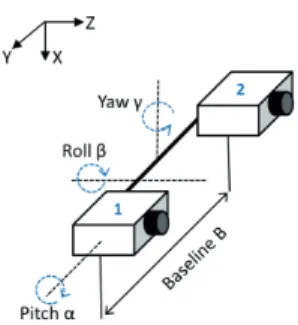
vari-ous errors in camera alignment can occur in the camera system in the basic (stereo) state. The errors in camera ro-tation are investigated in this work; these errors are repre-sented by error angles , and . The situation is shown in Fig. 1. There are two various practical situations which can be represented by these errors. In the first case, the cameras were originally in normal positions with parallel optical axes. In this situation angles represent real error in the physical position of the cameras. In this case, positions of the corresponding points differ only in horizontal position if cameras alignment is correct. However, this assumption is not valid if the cameras are not in perfect normal posi-tion. Therefore, the corresponding points cannot be found if we suppose a precise stereoscopic system because corre-sponding points are being searched only in the same row.
Fig. 1. Normal scanning system with two cameras (possible
fault angles are marked).
In the second case, the cameras were originally in the general positions and were transformed to the stereoscopic state by using the projective matrix obtained during exte-rior calibration. The calibration can be incorrect and then the angles represent error in the calibration. The geometry is represented by the projection matrix and determined by the interior and exterior calibration of the cameras. There-fore, camera calibration is a very important step in deter-mining the spatial coordinate from stereo images in the viewpoint of precision. In this article, we will examine error in the determination of space coordinates depending on the inaccurate establishing of mutual camera positions. Imperfect exterior calibration affects finding the corre-sponding point and vice versa. We determine the exterior calibration of the camera by using found corresponding points. Therefore, wrongly determined corresponding points cause incorrect determination of exterior calibration. Subsequently, incorrect exterior calibration causes inaccu-rate reconstruction of the spatial coordinates.
3.
Normal Camera Alignment
The coordinate system is affected by the error in cam-era alignment. Consequently, image coordinates of the spatial points are changed. Therefore, we first derived gen-eral formulas for calculating errors in all spatial coordi-nates in dependency on the wrongly determined image co-ordinates. The relation for error in depth Z is deduced in [4]. Formulas for errors in the other two dimensions X
relations for wrongly determined image coordinates in de-pendency on error in camera alignment x'2 and y' are found. The relations are derived from geometrical situations by using trigonometric functions. Therefore, these relations are various for various calibration errors. Subsequently, this relation is substituted to the general relations.
3.1
Expression of the General Equations
Firstly, formulas for calculating spatial coordinate Z
in situations without and with error in camera alignment are determined. The following equations were obtained by relationships describing simple stereophotogrammetry [4]
1 2 x x B f = Zobs c
, (1)
1 . 2 x x' B f = Ztru c
(2)
where Zobs is the observed absolute depth from the image plane to the object. Ztru is the real (true) absolute depth, fc is the focal length of both cameras (we assume the simple case, that cameras are the same), B is the stereo base (length of the base line), x1 is the correct (true) position of the measured point in the first image obtained by the first camera, x2 is the true position of the measured point in the second image obtained by the second camera and x'2 is the error (observed) position of the particular pixel in the sec-ond image captured by the real secsec-ond camera. The error is calculated as the difference of the real and observed depth of the point.
ΔZ = ZtruZobs, (3)
after substituting (1) and (2) into (3) we obtain
2 2
2 1
Δ tru
x x' Z = Z
x x
. (4)
Formula (3) represents the general error of the spatial coordinate Z.
Subsequently, we deal with the derivation of the gen-eral formula for errors X and Y. The procedure is similar to the derivation formulas for . Using known stereo-grammetric relations and basic mathematical operations, the following relationships were obtained
2 2 1 2 2 1
2 1 2 2
'
Δ
'
,
x x x x x x
X = B
x x x x
, (5)
22 11
2 22
1 'Δ
'
, y x x y x x Y = B
x x x x
. (6)
The coordinates x'2andy'are determined and substi-tuted in the next step. The formulas for coordinates have been derived for each situation (errors in three various angles) separately.
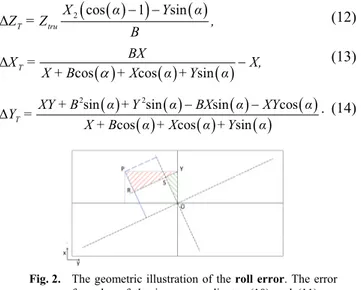
Firstly, we assume that the first camera is perfectly calibrated and its optical axis is identical with the axis z of the coordinate system (with the center in the focus). The optical axes of the second camera are parallel to the optical axes of the first camera. However, the second camera has incorrect calibration. The error is in the angle about the optical axis y. The geometric situation is shown in Fig. 2. Based on stereogrammetry, the following substitutions can be used [5]:
Z X f =
x1 c , (7)
Z B X f =
x1 c , (8)
Z Y f =
y c . (9)
From Fig. 2, it is obvious that x'2 is equivalent to ab-scissa RS, which can be expressed as x'2 = RY – SY. It can be determined from triangle OSY, that SY = y sin(
and from triangle PRY RY = x2 cos(). Consequently, we can write, using equations (7)-(9)
α Y
α X=
y'2,P cos sin . (10)
Similarly, y' can be determined as y' = OS + RP . The ab-scissa is derived from triangle OSY, where y = OY is the hypotenuse and from triangle RPY, where x2 = PY is the hypotenuse. Therefore
α +Y
α X=
y'2,P sin cos . (11)
Consequently, formulas (9) and (10), which represent error in image coordinates, caused by camera rotation, are successively substituted into formulas (4), (5) and (6), which express general errors of spatial coordinates caused by the error of image coordinates. The final equations for errors in all spatial coordinates have after mathematical modification the following forms
2 cos 1 sin
Δ T tru
X α Y α
Z = Z ,
B
(12)
Δ
cos cos sin
T
BX
X = X,
X + B + X α +Y α
(13)
2 2
sin sin sin cos
Δ
cos cos sin
T
XY + B α +Y α BX α XY α Y =
X + B α + X α +Y α
. (14)
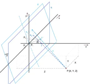
Subsequently, we assume that the first camera is per-fectly calibrated and aligned with the bar. The calibration of the second camera is perfect except for a certain rotation angle about a line which is parallel to the bar. An impor-tant fact is that the epipolar line is no longer parallel with the bar. The spatial model of this situation was used to de-rive a precise formula (see Fig. 3). The derivation is based on finding the intersection point of the plane and the ab-scissa u (denoted in Fig. 3). Firstly, the abscissa u passes through points P[X, Y, Z] and F'[fc·sin(, 0, fc·sin(]. The plane is described by a general equation by using three points which lie on it P1[0, 0, 0], P2[1, 0, 0] and P3[0, sin(), cos()]. Then, the abscissa and plane is de-scribed by the parametric equations. Subsequently, the segment line equation is substituted into the plane equa-tion. After this substitution, the final position of x'2 and y'2 is obtained. After mathematical operations, simplified for-mulas are obtained
f +Y
Z Xf = x' c c P sin cos
2, , (15)
f +Y
Z Zf Yf = y' c c c P sin cos sin cos cos 2 2, . (16)
Consequently, formulas (15) and (16) which represent error in image coordinates caused by camera rotation, are successively substituted into formulas (4), (5) and (6), which represent general errors of spatial coordinates caused by error of image coordinates. After mathematical modification, the final equations for errors in all spatial coordinates have forms
Δ cos sin 2 T c XZ XZZ = ,
B Z f +Y B
(17)
sin
1cos sin cos 0.5 2 2 cos C Z X B f + Y + f Z xf Zf + Yf B + Y = Y c c c c c T
, (18)
where C1 =
Zcos
fc+Ysin
.
2Δ ,
1 cos T
c
BXZ X = Y +
XZ f B + X + C
(19)
where C2 =BZcos
+BYsin
XYsin
.Subsequently, we assume that the first camera is per-fectly calibrated and its optical axis represents the z axis of the ordinate system with the center in the focus. The cali-bration of the second camera is perfect except for a certain rotation angle about the y axis.
A spatial model of this more complicated situation was used for deriving these errors. The camera focus changes its position. The root of the problem lies in finding the point of intersection of the plane and line section u.
Fig. 3. The geometric illustration of the pitch angle . The dark blue plane represents the plane of the image with-out error. The sky blue plane represents the plane of the scannedimage with error. The error formulas of the image coordinates (15) and (16) are derived using this image.
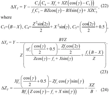
Fig. 4. The geometric illustration of the yaw angle . The dark blue plane represents the plane of the image with-out error. The sky blue plane represents the plane of the image with error. The error formulas of the image coordinates (19) and (20) are derived using this image.
Firstly, the line segment u passes through points P[X, Y, Z] and F'[0, fc·sin(), fc·sin()]. The plane is de-scribed by a general equation by using three points which lie on it P1[0, 0, 0], P2[1, 0, 0] and P3[0, sin(), cos()]. The procedure for deriving the formulas is the same as in the previous case; after mathematical operations, simplified formulas are obtained.
f +X
Z Zf Xf = x' c c c P sin cos sin cos cos 2 2, , (20)
f +Y
Z Yf = y' c c P sin cos
Formulas (20) and (21), representing error in image coordinates caused by camera rotation, are substituted into formulas (4), (5) and (6), which represent general errors of spatial coordinates caused by error of image coordinates. After mathematical modification, the final equations for errors in all spatial coordinates have forms
3 4 5
3 5 cos Δ cos sin c T c
C C Xf + XZ C
X = Y ,
f C BZ BX + XZC
(22)
where
C3=
BX
, C4=
+X
Z sin 2 2 sin 2 2
, C5=
0.5 2 2 cos + ,
Δcos cos 2
0.5 2 2 cos sin T c c c c BYZ
Y = Y ,
Zf
xf +
f B X
Z +
Z f + X Z
(23)
cos0.5 cos sin
2 cos sin c c T c c Xf Zf XZ Z B
Bf Z f X
. (24)
3.2
Experiments and their Results
The correctness of our derived formulas was verified experimentally. A free version of commercial special soft-ware (Autodesk 3DS MAX [21]) was used for rendering a simple virtual scene in these experiments. The used scene contains six spheres (see Fig. 5). This scene was obtained by virtual camera rendering with precisely set parameters:
translation between cameras, so-called stereo base B, rotation of the camera and ,
focal distance f,
sensor size dS (size of diagonal).
The examples of the rendered image are in Fig. 5. The experiment is based on finding correspondences for the particular points in the rendered scene. The image positions (x1 and y1) of the investigated particular points in the right image are known. The significant points are selected whose correct correspondences can be determined easily and un-ambiguously. Subsequently, the positions of the corre-sponding points in the left image without error in rotation (x2 and y2) are found. Then we compute the theoretical po-sition of the point in the image obtained by rotating the left camera by using Zhao's formula x'2, Z, y'2, Z and by our pro-posed formula x'2, P, y'2, P. Subsequently, the position of the point in the rotated image was found x'2, F, y'2, F. In the next step, the computed and found coordinates are compared.
Spatial coordinates of the given point are computed by using the position of the corresponding points
positions of the points in the left (x1 and y1) and right (x2 and y2) images in an ideal stereoscopic system (Xtru, Ytru, Ztru),
image positions calculated by the proposed formulas in stereoscopic system with some rotating error (Xobs, Yobs, Zobs).
The differences between correct and incorrect spatial coordinates are calculated (XC, YC, ZC) by the follow-ing equation
,
obs tru X
X Xc
(25)
Simultaneously, the theoretical errors caused by rota-tion (XT, YT, ZT) are computed by using proposed for-mulas (12)–(14),(17)–(19),(22)–(24). The results for all three error angles are in Tab. 1. Subsequently, theoretical and practical errors are compared. Obviously, these errors are equal for every three types of error rotations (roll, pitch, yaw). Therefore, the obtained relations can be used for estimating the error caused by camera rotation.
The largest difference between the results obtained by formulas proposed in [7] and by our newly proposed for-mulas are for rotation error roll with error angle . The formula proposed in [7] is only valid if the vertical image position is 0 (points lie on the vertical center of the image).
a) b) c)
Fig. 5. The rendered image used for verifying the formula for error in image coordinates: a) left image without roll, b) right image without roll, c) left image with roll of the camera by 5 degrees.
There are many various dependencies which can be investigated and plotted. It is possible to monitor depend-encies on the nine input parameters: focal length fc, stereo base B, horizontal image position or alternative hori-zontal space positionX, vertical image position yim or alter-native vertical space position , parallax or alternative depth space coordinate and error angle. Then it is possi-ble to investigate: error of vertical image position, error of horizontal position and errors of three space coordinates. The plotting of all dependencies would be space-consum-ing. Some of the important and interesting dependencies are plotted in the following figures. The relative errors are plotted because they more aptly inform us about error se-verity. The percentage of relative errors was calculated using the following equation
100 abs rel X X X
(26)
Roll error Pitch error Yaw error c
[pixel] pixel 1 pixel 2 pixel 3 pixel 4 pixel 1 pixel 2 pixel 3 pixel 4 pixel 1 pixel 2 pixel 3 pixel 4 x1 56.00 134.00 79.00 46.00 607 471 436 612 554 452 427 451
y1 113.00 0.00 0.00 111.00 300 163 371 160 300 197 351 300
x2 263 298 227 128 399 263 228 404 400 298 273 297
y2 113 0 0 111 300 163 371 160 300 197 351 300
x’2, F 252.00 297 228 114.0 399 264 228.00 404.00 575 472 448 472
x’2, Z 261.99 296.87 226.13 127.51 399.93 263.08 228.11 403.99 574 472.65 447.50 472.65
x’2, P 252.15 296.87 227.66 112.85 399.01 264 228.57 403.97 573.64 472.1 447.35 472.10
y’2, F 135 26 286 238 368.44 233 440.20 230 300 197 351 300
y’2, Z --- --- --- --- --- --- --- --- --- --- --- ---
y’2, P 135.44 25.97 284.92 237.92 135.45 233.39 441 230.42 300 877.30 349.72 298.66
[mm]
Xtru 248.90 93.06 94.05 43.40 298.56 197.60 248.08 5.77 0 198.70 247.40 200.65
Xobs 247.09 93.23 94.42 41.44 298.57 197.13 247.93 5.73 2731.2 1042.9 698.06 1028.6 XC 1.80 0.22 0.37 0.12 0.01 0.47 0.14 0.04 2731.3 844.20 450.66 827.95 XT 1.81 0.24 0.26 0.18 0.01 0.47 0.14 0.04 2682.0 877.30 450.59 877.30
Ytru 106.94 0 0 104.7 0.00 197.6 102.40 201.92 0 200.65 99.35 0
Yobs 132.76 18.10 16.97 55.85 100.61 96.52 202.77 100.35 0 1672.1 847.72 0 YC 25.82 18.10 17.97 48.85 100.61 294.11 305.18 302.27 0 1672.1 847.07 0 YT 25.83 18.06 17.99 48.81 100.61 294.11 305.17 302.25 0 1731.2 3749.4 0
Ztru 1886.8 1385.7 2371.5 1886.8 2884.6 2884.6 2884.6 2884.6 3896 3896.1 3896.1 3896.1
Zobs 1953.1 1389.3 2377.7 1801.8 2867.9 2897.6 2892.6 2884.2 31579 28571 29485 32467 ZC 66.33 3.64 6.11 84.99 16.68 13.23 7.99 0.40 34475 32467 33382 33748 ZT 64.58 3.64 6.19 89.83 16.68 13.23 7.97 0.39 34445 33748 33382 32447
Tab. 1. The verification of the proposed formulas for calculating error image positions (x’2,P,y’2,P) and formulas for calculation of the error of
the spatial coordinates XT, YT, T for all three error rotation between cameras.
Notes:
x1 Horizontal image position determined by the corresponding point detector in image rendered by the right camera with no error.
y1 Vertical image position determined by the corresponding point detector in image rendered by the right camera with no error.
x2 Horizontal image position determined by the corresponding point detector in image rendered by left camera with no error.
y2 Vertical image position determined by the corresponding point detector in image rendered by left camera with no error.
x’2, F Horizontal image position determined by the corresponding point detector in image rendered by theleft camera with error in alignment.
x’2, Z Horizontal image position calculated by relation from [7] in image rendered by the left camera with error in alignment.
x’2, P Horizontal image position calculated by the proposed formulas in image rendered by the left camera with error in alignment.
y’2,F Vertical image position determined by the corresponding point detector in image rendered by the left camera with error in alignment.
y’2, Z The relation for calculation of vertical image position in image wasn’t proposed in [7].
y’2, P Vertical image position calculated by the proposed formulas in image rendered by the left camera with error in alignment.
Xtru Correct spatial coordinate, calculated by using point’s image coordinates x1, y1, x2, y2 in images obtained camera system with no error.
Xobs Incorrect spatial coordinate, calculated by using point’s image coordinates x1, y1, x’2,Fy’2,F in images obtained camera system with error
in alignment.
XC The differences between correct Xtru and incorrect spatial coordinates Xobs.
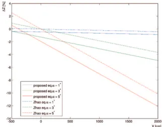
Fig. 6. The dependencies of the relative error Δ on the roll angle and space coordinates . Used sensing system parameters B = 75 mm, f = 8.5 mm.
We analyze error for all three rotating errors (roll, pitch and yaw). We begin with roll between cameras. Fig. 6 shows relative error in depth (coordinate Z) in de-pendency on space coordinate X of the object. The error angle of the roll is a parameter of these dependencies. The error is related to depth (space coordinate Z). This figure serves for comparing the error calculated by the pro-posed formulas (correctness verified) and error calculated by the formula proposed in [7]. The error calculated by the formula proposed in [7] is plotted with dashed lines. The errors calculated by the newly proposed formulas are plot-ted with solid lines.
Figures 7–9 show the relative errors of all spatial co-ordinates X, Y and Z in dependency on the parallax px, horizontal image coordinate xim and vertical image coordi-nate yim. The error angle of the roll is a parameter of the curves.
Subsequently, we analyzed the pitch between cam-eras. Dependencies are in Figs. 10–12. The coordinate is the most sensitive to error in pitch and its relative error reaches a value of about 5% for angle 1° while the error in the next two spatial coordinates reached values up to 5% for a given angle. Therefore, the error in image coordinate
y has crucial importance for the accuracy and feasibility of calculating spatial coordinates. Formula (5) for calcu-lating the error in coordinate Y contains the vertical image coordinate yim too. This error is not considered in article [7]. However, the error in vertical coordinate y is more significant for pitch than the error in horizontal coordinate
xim. Moreover, the most critical problem is feasibility of the calculation. Calculating the error assumes correctly finding corresponding points in the image obtained by the rotated camera. The corresponding points are found in the row where they lie in the first image. This means that the corre-sponding point is not found if the vertical image coordinate is changed due to rotation. This hypothesis is valid for all
error in alignment of the camera system. Consequently, the corresponding points cannot be found by a simple algo-rithm working in one row if there is the assumption that error in alignment occurs. Therefore pitch error is the most critical error from the view of the possibility of finding correspondences.
Subsequently, we analyzed the yaw between cameras. Dependencies are in Figs. 13–15. There is opposite situa-tion than in the previous pitch. Coordinate X is the most sensitive to the error in yaw and its relative error reaches a value of about 10 percent for an angle of 1o. The yaw error is the most critical error from the viewpoint of overall error. The parallax px is strongly influenced if the horizon-tal image coordinates in one image is strongly changed. The horizontal parallax is included in equations for calcu-lating all spatial coordinates. Subsequently, all three spatial coordinates are critically influenced (see Tab. 1.).
Fig. 7. The dependencies of the relative error X on the roll angle between cameras and a) parallax px, b) image
vertical coordinate yim, c) image horizontal coordinate
xim.
Fig. 8. The dependencies of the relative error Y on the roll angle between cameras and a) parallax px, b) image
vertical coordinate yim, c) image horizontal coordinate
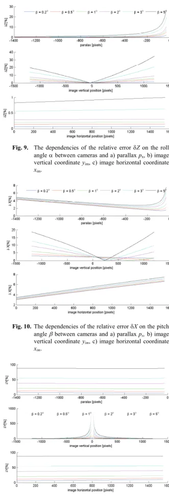
Fig. 9. The dependencies of the relative error Z on the roll angle between cameras and a) parallax px, b) image
vertical coordinate yim, c) image horizontal coordinate
xim.
Fig. 10. The dependencies of the relative error X on the pitch angle between cameras and a) parallax px, b) image
vertical coordinate yim, c) image horizontal coordinate
xim.
Fig. 11. The dependencies of the relative error Y on the pitch angle between cameras and a) parallax px, b) image
vertical coordinate yim, c) image horizontal coordinate
xim.
Fig. 12. The dependencies of the relative error Z on the pitch angle between cameras and a) parallax px, b) image
vertical coordinate yim, c) image horizontal coordinate
xim.
Fig. 13. The dependencies of the relative error X on the yaw angle between cameras and a) parallax px, b) image
vertical coordinate yim, c) image horizontal coordinate
xim.
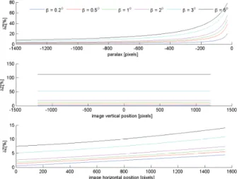
Fig. 14. The dependencies of the relative error Y on the yaw angle between cameras and a) parallax px,b) image
vertical coordinate yim, c) image horizontal coordinate
Fig. 15. The dependencies of the relative error Z on the yaw angle between cameras and a) parallax px, b) image
vertical coordinate yim, c) image horizontal coordinate
xim.
4.
General Alignment
The cameras of the 3D generalized sensing system can have arbitrary positions in a space. Then, the error in camera alignment is equal to the error in rotation matrix R, which is obtained by a set of corresponding points. The coordinate system center is usually located at the optical center of the first camera. Therefore, the rotation angles φ, κ, ω and matrix R represent the relation between both cam-eras and between the coordinate system and the second camera. Assuming that we know rotation angles φ, κandω between the optical axis of the camera and axes of the co-ordinate system, then the theoretical rotation matrix R of the camera can be obtained by using the following relation (27) [22]. Conversely, the rotation angles can be deter-mined from rotation matrix R. The rotation matrix R is obtained by using an 8-point algorithm from a set of corre-sponding points. Therefore, errors in determining the cor-responding points cause error in rotation matrix R. The error in camera alignment and correspondence problem are closely related. This issue will be solved in detail in our future works. This paper contains only a brief analysis and description of the executed test.
The resulted error of the rotation matrix is given by a combination of the error in each corresponding point. Therefore, influence of the error in a particular dence on the results is affected by error in other correspon-dences. The same error in determining the same corre-sponding point can variously influence the calculation of the rotation matrix. The errors are influenced by many factors. The next aspect is mutual camera positions. It is not practically possible to investigate all possible combina-tions. All of the executed experiments represent statistical sensitive analyses. The received results are valid only for specified conditions. Nevertheless, results may be grounds for some general conclusions and hypotheses.
In the first experiment, the additive white Gaussian noise with various Signal to Noise Ratio (SNR) is added to all the accurately found corresponding points. The Monte Carlo method was used. One thousand repetitions of recon-struction with a particular level of noise were executed. Subsequently, the average value, standard deviation and the worst case were determined. The experiment can be described in several steps:
determination of the rotation matrix Raccur by using accurate corresponding points,
determination of the correct mutual angles between cameras (φ, κ, ω) by using Raccur and relationship (27),
degradation of the set of corresponding points posi-tions by adding noise (error in all points defined by SNR),
calculation of the rotation matrix Rerror from the set of degraded corresponding points,
calculation of the rotational angles of the cameras φ, κ, ωfrom matrix Rerror,
error analysis of rotation angles.
In the second experiment, only one point is debased by an accurately defined error. Other correspondences are accurate. The worst case analysis is executed again. The most sensitive point and most affecting point are found.
In the next scenario, the error angles α, , were added to the original angles between cameras φ, ω and κ. Consequently, the rotation matrix R was directly corrupted. This scenario follows from the previous one which investi-gated dependency and sensitivity of the error in rotation matrix R on the errors in corresponding points. The aver-age error and standard deviation in each spatial coordinate was investigated.
The last experiment analyzes the situation with known error in two and more corresponding pairs. The error in one point was compensated by the error in another point in some situations.
The executed experiments and obtained results can be used especially for a few purposes:
demonstrating the importance of finding correspond-ing points correctly.
get an idea of how an error can occur.
obtaining the relation between the error of stereo camera alignment and errors in finding corresponding points,
design process for estimating possible errors of 3D re-construction.
cos cos cos sin sin sin sin cos cos sin sin sin sin cos cos sin cos cos sin cos sin sin cos sin sin sin cos cos cosR . (27)
5.
Conclusion
The paper deals with the analysis of achievable accu-racy of 3D model scene reconstruction. The accuaccu-racy is influenced by many aspects. We investigated effects of camera alignment errors on estimating all three spatial co-ordinates and their errors. The paper extends previous work [7], [10]. The practical experiment revealed that one previously derived equation for expressing the error of the depth coordinate caused by errors in camera rotation is incorrect. Therefore, a new equation for depth error esti-mation is derived and its correctness was proven by ex-periment. Subsequently, the equations for estimating error in the remaining two spatial coordinates were derived and their correctness was proven by experiments. The relative errors are used for presenting the results. The relative ex-pression has greater and general informative value than the absolute one.
Some conclusions can be deducted from shown graphs. The accuracy of the spatial coordinate X is most sensitive on the yaw () between cameras (Fig. 13). More-over, the error of coordinate X for yaw is very sensitive to the size of the angle . The accuracy of the spatial coordi-nate Y is most sensitive to the pitch () between cameras
(Fig. 11). The accuracy of the spatial coordinate Z is most sensitive to the yaw () between cameras (Fig. 15). These conclusions are confirmed by the results in Tab. 1. These dependencies are in accordance with initial assumptions. The yaw error is the most critical error from the view of overall error. The parallax px is strongly influenced if the horizontal image coordinate x in one image is strongly changed. The horizontal parallax is included in equations for calculating all of spatial coordinates. Subsequently, all three spatial coordinates are critically influenced. The rela-tive errors are critical especially for small image nates and parallax. The relative errors of the spatial coordi-nates are not dependent on the image coordinate y for yaw between cameras. However, these errors are very sensitive to the size of the angle .
The second part deals with a generalized camera system. This issue is closely related to the inaccurate de-termination of corresponding points and error in camera alignment. Exterior calibration is considered as the trans-formation between these two camera systems. Then, the consequence of error in the rotation matrix is considered as the error in the resulting stereo alignment. The error in the rotation matrix is caused by inaccurate determination of corresponding points. The statistical analysis was per-formed and the worst case was determined. This analysis is the first step to future work whose aim is to determine the stochastic model of the error in a generalized camera system.
Acknowledgments
Research described in this paper was financed by the Czech Ministry of Education in frame of National Sustainability Program under grant LO1401. For research, infrastructure of the SIX Center was used.
References
[1] KYTÖ, M., NUUTINEN, M., OITTINEN, P. Method for measuring stereo camera depth accuracy based on stereoscopic vision. In Proceedings of SPIE/IS&T Electronic Imaging,
Three-Dimensional Imaging, Interaction, and Measurement. San
Francisco (California, USA), 2011, 9 p. ISBN: 9780819484017 [2] CHANG, W., CHO, K., RYU, W., LEE, S.-Y. Error cost function
for mirror-based three-dimensional reconstruction. Electronics
Letters, 2014, vol. 50, no. 16, p. 1134–1136. DOI:
10.1049/el.2014.0496
[3] SIN-YI JIANG, CHANG, N.Y.-C., CHIN-CHIA WU, et al. Error analysis and experiments of 3D reconstruction using a RGB-D sensor. In IEEE International Conference on Automation Science
and Engineering (CASE 2014). Taipei (Taiwan), 2014, p. 1020 to
1025. DOI: 10.1109/CoASE.2014.6899451
[4] GREWL, P. K., VISWANATH, K. S., GOLNARAGHI, F. Minimization of position uncertainty using 3-D stereo imaging technique for the real-time positioning of a handheld breast tissue anomaly detection probe. In Fourth International Conference on Computing, Communications and Networking Technologies
(ICCCNT 2013). Tiruchengode (India), 2013, 6 p. DOI:
10.1109/ICCCNT.2013.6726646
[5] LI, J., WANG, J., ZHOU, W., et al. Robot pose estimation and accuracy analysis based on stereo vision. In Proceedings of the IEEE Ninth International Conference on Mobile Ad-hoc and
Sensor Networks (MSN,2013). Dalian (China), 2013, p. 555–559.
ISBN: 978-0-7695-5159-3. DOI: 10.1109/MSN.2013.107 [6] ZHANG, T., BOULT, T. Realistic stereo error models and finite
optimal stereo baselines. In IEEE Workshop on Applications of
Computer Vision (WACV 2011). SnowBird (USA), 2011, p. 426 to
433. ISBN: 978-1-4244-9496-5. DOI: 10.1109/WACV.2011.5711535
[7] ZHAO, W., NANDHAKUMAR, N. Effects of camera alignment errors on stereoscopic depth estimates. Pattern Recognition, 1996, vol. 29, no. 12, p. 2115–2126. ISSN 0031-3203. DOI: 10.1016/S0031-3203(96)00051-9.
[8] CHANG, C., CHATTERJEE, S. Quantization error analysis in ste-reo vision. In Conference Record of the 26th Asilomar Conference
on Signals, Systems and Computers. Pacific Grove (USA), 1992,
vol. 2, p. 1037–1041. ISBN: 0-8186-3160-0. DOI: 10.1109/ACSSC.1992.269140
[9] FOOLADGAR, F., SAMAVI, S., SOROUSHMEHR, S. M. R. Geometrical analysis of altitude estimation error caused by pixel quantization in stereo vision.In Proceedings of the 20th Iranian
Conference on Electrical Engineering (ICEE 2012). Tehran (Iran),
[10] STANCIK, P. Optoelectronic and photogrammetric measuring systems. PhD Thesis (in Czech). Brno University of Technology, Faculty of Electrical Engineering and Communication, 2008, 89 p. [11] GALLUP, D., FRAHM, J.-M., MORDOHAI, P., POLLEFEYS,
M. Variable baseline/resolution stereo. In Proceedings of IEEE Conference on Computer Vision and Pattern Recognition.
Anchorage (USA), 2008, 8 p. ISBN: 978-1-4244-2243-2. DOI: 10.1109/CVPR.2008.4587671
[12] BELHAOUA, A., KOHLER, S., HIRSH, E. Error evaluation in a stereovision-based 3D reconstruction system. EURASIP Journal
on Image and Video Processing, 2010, vol. 2010, no. 2, p. 1–12.
DOI: 10.1155/2010/539836
[13] BELHAOUA, A., KOHLER, S., HIRSH, E. Estimation of 3D reconstruction errors in a stereo-vision system. In Proceedings of
Modeling Aspects in Optical Metrology II, June 2009,vol. 7390.
p. 1–10. DOI: 10.1117/12.827346
[14] KAMENCAY, P., BREZNAN, M., JARINA, R., et al. Improved depth map estimation from stereo images based on hybrid method.
Radioengineering, 2012, vol. 21, no. 1, p. 70–78, ISSN
1210-2512.
[15] SCHARSTEIN, D., SZELISKI, R. A taxonomy and evaluation of dense two frame stereo correspondence algorithms. International
Journal of Computer Vision, April 2002, vol. 47, no.1-3, p. 7–42.
DOI: 10.1023/A:1014573219977.
[16] FOOLADGAR, F., SAMAVI, S., SOROUSHMEHR, S.M.R., SHIRANI, S. Geometrical analysis of localization error in stereo vision systems. IEEESensors Journal, Nov. 2013, vol. 13, no. 11, p. 4236–4246. DOI: 10.1109/JSEN.2013.2264480
[17] DWARAKANATH, D., GRIWODZ, C., HALVORSEN, P., LILDBALLE, J. Study the effects of camera misalignment on 3D measurements for efficient design of vision-based inspection systems. Artificial Intelligence: Methods and Applications, 2014, vol. 8445, p. 150–163. ISBN: 978-3-319-07063-6. DOI: 10.1007/978-3-319-07064-3_13
[18] DING, X., XU, L., WANG, H., et al. Stereo depth estimation under different camera calibration and alignment errors. Applied Optics, 2011, vol. 50, no. 10, p. 1289–1301. DOI: 10.1364/AO.50.001289. [19] KNIGHT, J., REID, I. Active visual alignment of a mobile stereo camera platform. In Proceedings of IEEE International
Conference on Robotics and Automation (ICRA '00). San
Francisco (USA), April 2000, vol. 4, p. 3203–3208. ISBN: 0-7803-5886-4. DOI: 10.1109/ROBOT.2000.845156.
[20] RESKO, B., BARANYI, P. Stereo camera alignment based on dis-parity selective cells in the visual cortex. In ProceedingsofIEEE 3rd International Conf. on Computational Cybernetics (ICCC
2005). 13-16 April 2005, p. 285–290. ISBN: 0-7803-9122-5. DOI:
10.1109/ICCCYB.2005.1511588.
[21] Autodesk. Autodesk 3DS MAX 8[software]. Software available http://www.autodesk.com/.
[22] CRAIG, J. Introduction to Robotics: Mechanics and Control. 3rd
ed. Prentice Hall, 2004. ISBN 0201543613.
About the Authors …
Libor BOLECEK was born in Šternberk, Czech Republic in April 1985. He graduated from the Faculty of Electrical Engineering and Communication (FEEC), Brno University of Technology (BUT), in 2010. The field of his interest includes image processing, quality evaluation and photo-stereometric systems.