Tamililakkiya.V
*1,Vani K
*2, Lavanya A
*3and Anto Micheal
*4 *Department of Information Science and Technology, College of Engineering Guindy, Chennai – 600025.
[email protected], [email protected]2, [email protected]3, [email protected]
ABSTRACT
Craters, ridges and rocks are the features to be extracted in the lunar images. Proposed methodology deals with detection of linear feature such as (i) ridges, (ii) lineaments and (iii) nonlinear features like craters. All edges are identified as either crater or lineament. Therefore, all circular edges are recognized as craters edges, and those remained edges, which are not crater edges and low possibility of the noise, are recognized as lineaments in the remained edges. The Steps for lineament recognition includes the steps such as Crater Rim Elimination, Small Area Elimination and Lineament Classification. Ridges detection includes edge extraction using haar wavelet transform followed by morphological operations such as dilation and erosion.
For detection of non linear features such as craters, the most predominant feature on the lunar terrain, circular hough transform is used. But it fails to detect craters without proper connected edges because of presence of shadows in an image. This paper includes algorithms for shadow removal in the images which accounts for changes in illumination, visual appearance, and size. Results indicate that the detection rate is improved with shadow removal techniques.
KEYWORDS
Feature extraction, Shadow removal, linear feature, non linear feature, Ridges, Circular hough transform.
1.
I
NTRODUCTIONCraters are commonly found on the surface of planets, satellites, asteroids and other solar system bodies. The number and size of the crater is used to identify age of the surface which has craters. The relative ages between the surfaces of different bodies can also be identified. Generally, the crater is a bowl shaped depression created by collision or volcanic activities. Craters may have sharper and regular rims when they are younger and when the age of the crater increases regular rims leads to vague rims. Therefore, the craters are a fundamental tool to determinate the geological age and history of a surface.
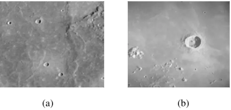
expert is a difficult task and time consuming endeavour, because planetary images are blurry, quite noisy, present lack of contrast, the quality of the images is generally low (i.e., it depends on illumination, surface properties and atmospheric state), the features that are present in the images can be barely visible due to erosion and the shadows present in the images, and uneven illumination, and the represented objects are not well defined. Therefore, it is highly desirable procedure to detect the position, structure, and dimension of each feature is a trustworthy automatic procedure. Figure 1 shows the Lunar image with impact craters. These features also exhibit different structures and variable sizes.
The wide range of crater dimensions (from a few meters to thousands of kilometers) with distinct conservation conditions (from very fresh and well contrasted to very old with vauge rims and filled or covered by other geological materials) occurring in quite diverse geo morphological settings has also made difficult the choice of adequate and unique parameters on the different automated approaches.
2.
R
ELATEDW
ORKSome have employed texture analysis for crater detection [1]. They calculate variance in each tile and use shadows (high local variance) to detect crater or rocks. Multiple boundary based approaches are merged to obtain the results [2]. In the first approach they have used images that are classified considering illumination. When shady and illuminated pattern is recognized, they fit a circle to the surrounding edges. Although abrupt brightness changes may reveal a lot about the surface under consideration, the presence of sensor data with correct illumination is often an unrealistic assumption to make. Wetzler et al.[3] have used various supervised learning algorithms, including ensemble methods (bagging and AdaBoost with feed forward neural networks as base learners), support vector machines (SVM), and continuously scalable template models (CSTM) to derive crater detectors from ground truthed images. Kim et al. [4] propose three staged crater detection system by eliminating noise in the image by extracting region of interest. They used primitive arcs are organized by graph and conic section fitting to detect the craters. Candidate craters are propagated to the last stage, where they are verified by a fitness measure and a false crater classifier based on artificial neural networks.
Honda et al. [5] have also combined machine learning approaches with boundary based methods. In the framework they have proposed, image is first binarized. To find craters, circular object detection is then applied using a combination of Hough Transform and Genetic Algorithm. Leroy et al. [6] have employed the same idea to isolate individual craters. Crater fitting algorithms are frequently used when researchers model the crater to be detected as a crater. Clustering techniques such as K-means are generally used for partitioning the feature points into set of candidate craters.
Bue et al.[7] have discussed limitations of optical image data and outlined an algorithm using solely digital elevation model. Lourenço et.al [8] developed the automated procedure for the identification of impact craters that they propose is constituted by three main phases organized in sequence: candidate selection, template matching and crater detection. Jon et.al [9] described the Radial Consistency algorithm developed as part of this work models impact craters as having localised rotational symmetry. In an image, a ridge occurs when there is a connected sequence of pixels having intensity values higher or lower than the neighborhood pixels. [2] Saint – Venant identified ridges as a loci of minimum gradient magnitude along level curve of a relief .
In this paper, we emphasize on linear edge extraction using HWT and binarization. Later, we move on to describe methodology for non linear feature extraction. Craters are extracted using circular hough transform. Before crater detection, removal of shadows present in the image is done. In the results, we compare the results obtained by non linear feature extraction before and after the shadow removal technique.
3.
M
ETHODOLOGYProposed system deals with detection of linear feature like ridges and nonlinear features like craters. Crater detection includes shadow removal followed by preprocessing and circular hough transform. Ridges detection includes edge extraction using haar wavelet transform followed by morphological operations, crater detection and ridges detection. Over all flow is shown in Figure 1.
Fig 1. System architecture for linear and non linear feature extraction
4.
L
INEAMENT RECOGNITIONorthogonal principal directions. These measure the maximum and minimum bend in the surface. A pixel is defined as a ridge if the maximum principal curvature at that pixel is a local maximum in some direction.
Lineaments recognition includes (i) Edge detection in DTM to extract all topographic features. (ii) Extraction of circular edge to find craters, and (iii) Recognition of lineaments. Edge detection is one of the most important parts of the recognition algorithm.
Edge detection includes the following steps: Edge extraction, binarization, Filtering, dilation and thinning.
4.1. Feature Extraction: Haar Wavelet Transform
The Haar transformation technique is used to form a wavelet since it is the simplest wavelet transformation method of all and can effectively serve our interests. In the Haar wavelet transformation method, low-pass filtering is conducted by averaging two adjacent pixel values, whereas the difference between two adjacent pixel values is figured out for high-pass filtering. The Haar wavelet applies a pair of low-pass and high-pass filters to image decomposition first in image columns and then in image rows independently. As a result, it produces four sub-bands as the output of the first level Haar wavelet. The four sub-bands are LL1, HL1, LH1, and HH1. Upto four levels of decomposition are done to get the detail image.
4.2. Energy Calculation
After taking the four or five level decomposition sub band images are obtained. For that sub band images find out the energy. The same procedure has to be followed for database all images. Energy is found using this equation (1)
1 1
( , )
( )
*
m n
i j
subband i j Energy subband
m n
= =
= - (1)
Find out the energy for all sub bands like this same procedure. Then store the all energy values of images in an array.
4.3. Binarization
Binarization of an image is a process representing an image using only two different pixel values. It is generally performed by classifying a gray scale image into two groups of pixels based on certain threshold value. Those pixel values greater than or equal to the threshold is set to a particular grey value and those below the threshold to another grey value. The proper threshold values depend on the quality of the images to be binarized. Automatic binarization algorithm proposed by Otshu is implemented in Matlab using the function graythresh.
4.4. Median Filter
4.5. Dilation
Dilation is a morphological transformation that produces an image that is the same shape as the original, but is a different size. Dilation stretches or shrinks the original figure. The description of a dilation includes the scale factor (or ratio) and the center of the dilation. The center of dilation is a fixed point in the plane about which all points are expanded or contracted. It is the only invariant point under dilation.
4.6. Thinning
Thinning process was adopted as method of advancement recognition rate from the binarized image. The thinned image is important in the recognition process, because the image is remained only topographic features. Hilditch method in thinning type was adopted in this process.
The thinning that is performed by the SUSAN binary post-processing follows a few simple rules which remove spurious or unwanted edge points and add in edge points where they should be reported but have not been. They fall into three categories; those removing spurious or unwanted edge points, those adding new edge points and those shifting edge points to new positions. The rules are now listed according to the number of edge point neighbours which an edge point has (in the eight pixel neighbourhood).
5.
L
INEAMENT DETECTIONWrinkle ridges are features created by compressive tectonic forces within the maria. These features represent buckling of the surface and form long ridges across parts of the maria. Some of these ridges may outline buried craters or other features beneath the maria
All edges are defied as either crater or lineament. Therefore, all circular edges are recognized as craters edges, and those remained edges, which are not crater edges and low possibility of the noise, are recognized as lineaments in the remained edges. The methodology for lineament detection is given in Figure 2.
Fig 2. Lineament recognition
6.
C
RATER DETECTION:
S
HADOW REMOVALBecause of the underexposure or illumination, there are some shadows in the image it results in invisibility of the details or incapable distinguish by human vision. To stand out more details the single-scale Retinex (SSR) and multi-scale Retinex(MSR) algorithm based on the Retinex theory can achieve the dynamic compression. So, for eliminating shadows the Retinex algorithm has been widely applied to the remote sensing, medical image, removing haze from the image.
Lunar Image Crater Rim Elimination
Small area Elimination
Ridge extraction
After the source image with more dark areas is enhanced using SSR or MSR, the resulted image color is weaker and have the more details in shadow. Furthermore, if the color of the image is restored, the partly details in shadow are invisible too, accordingly the information is lost. So, the fusion method is proposed,in order to solve this problem.
6.1. Color Image Fusion
The fusion method proposed by this paper is performed based on the only one single image with many shadows in which the details is invisible. First, the original image is enhanced by MSR using auto-stretching method, in order to more details in shadow is visible. Then, using DWT the source image and the enhanced image are fused.
The color image fusion method can be performed in the following steps:
1) Color space of the original image and the enhanced image using MSR into the IHS color space transformation is made.
2) Using DWT decompose the two intensity components respectively.
3) Fusion rule: for detail coefficients select the maximum absolute value and average between the approximate coefficients.
4) By inverse DWT the fused coefficients are reconstructed into the new intensity component V’. 5) Consider the V’ as the intensity component of the original image, and transform the new intensity, the saturation, and the hue, components back into RGB color space.
6.2. Preprocessing
Removal of shadows present in the image is done before crater detection, which uses the MSR to enhance the color images. It can achieve adequate enhancement of shadowed detail and fails to rendition. The DWT combines the good color rendition and more details in shadows derived from the source image and the enhanced image into a fused image by DWT. Using this method, the fused image not only can preserve more details in shadows but also is more adaptable to the human visual perception. The resulting image of shadow removal is shown in Figure 3.
Fig 3. (a) Original Lunar Image 1, (b) Original Lunar image 2, (c) Image 1 after shadow removal, (d) Image 2 after shadow removal
(a) (b)
The 5*5 median filter and Gaussian filter is used for noise reduction and the original image is blurred as the small size of craters can’t be extracted synchronously. The median filter is a nonlinear digital filtering technique, used to remove noise. Such noise reduction is a pre-processing step to improve the results of later pre-processing. Median filtering is very widely used in digital image processing as, it preserves edges while removing noise.
Gaussian filter is a filter for which impulse response is a Gaussian function. Gaussian filters are designed to give no overshoot to a step function input as they minimizing the rise and fall time.
Fig. 4 (a),(b) Filtered images using median and gaussian filter
Steps involved in crater detection:
• Shadows are removed based on the multi-scale Retinex (MSR) and discrete wavelet
transform (DWT).
• The noise is smoothed by applying a Gaussian filtering and a median filtering operation.
• Compute image gradient Ig, by using the canny edge detector.
• By applying a non-maximum suppression algorithm followed by an Hysteresis thresholding to Ig, a binary gradient image, Ib, showing the contours of the objects is obtained.
• A circular Hough transform (CHT) is used to identify the seed points to detect these
structures from Ib.
• For every pair of points that are detected as edge points in Ib and exhibit opposite
gradient directions, an accumulator, corresponding to the median point between them, is incremented of a unit value.
• The maxima of the accumulator are taken as centers of the circle
6.3. Edge detection
Canny operator was used to discover the optimal edge detection algorithm. Once this process is complete we have a binary image I (x, y) where each pixel is marked as either an edge pixel or a non-edge pixel. From complementary output of the edge tracing step, the binary edge map obtained in this way can also be treated as a set of edge curves, which after further processing can be represented as polygons in the image domain. Then, to detect the edges, the image gradient is computed by using the Canny edge detector. Result of a canny edge detector is shown in Figure 5.
Shapes that are not clear may not be easily expressed using a small set of parameters. We must explicitly list the points on the shape for these cases. We make a table that contains all the edge pixels for our target shape. Position relative to some of the reference point for the shape can be stored for each pixel.
Circular Hough Transform and can be expressed as follows: 1. Find all the desired feature points in the image
2. For each of the feature point
3. For each of the pixel i on the target’s boundary 4. Get the relative position of reference point from i 5. Add the offset to the pisition of i
6. Increment this position in the accumulator 7. Find the local maxima in the accumulator
8. If it is desired, map each maxima in the accumulator back to image space using the target boundary table.
In order to identify the seed points that detect the structures from binary gradient image, Ib, the Circular Hough Transform is used. The median point between every pair of points that are detected as edge points in Ib and exhibit opposite gradient directions, an accumulator, is incremented by a unit value. The maxima of the accumulator are taken as the canters of the craters or circles. Accumlation array of circular hough transform is shown in Figure 6.
Target range of crater diameter for recognition is an important value in this recognition algorithm, because the vote for big craters gets priority if the range of recognition is not decided .Small
(a) (b)
Fig.5 (a) (b) Detection of edges using canny operator
(a) (b)
craters can be recognized by defining the target range. Therefore, the target range of crater diameter should be limited for the effective crater recognition. Experimental results of crate detection shows that the CHT can find craters with incomplete rims, nested craters, and craters overlaid on the rim of another crater
7.
R
ESULTS ANDD
ISCUSSIONWe tested the proposed system on a set of 20 images from Chandrayaan-1, Selene (Japan moon mission), with different characteristics in terms of size, noise, and content.
7.1. Ridge extraction
Lunar ridges are a kind of familiar linear structures developed on the lunar surface. Single lunar ridges are usually distributed in the form of broken lineation, and, as whole, lunar ridges are trapezoidal or annular in shape around the maria. As to the formation mechanism, only volcanism or tectonism was emphasized in the past, but the two processes are seldom taken into combined consideration. Crater detected image is given as an input to ridges detection and the edges identified as craters are eliminated and processed to find ridges.
7.2. Crater extraction
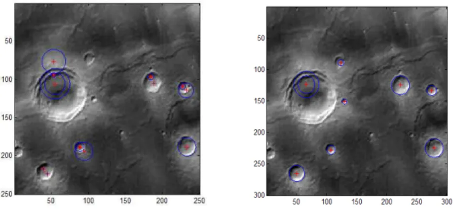
Crater detection with and without shadow removal has been done and resultant table is shown in Table 1, with the source images shown on in the Figure 8, 9 and 10.
Figure 8 (a) Crater detected with center for Image A
(a) (b)
Figure 8 (b) Crater detected with center for Image B
Figure 9. Crater detected before and after shadow removal for Test Image 1
Figure 10. Crater detected before and after shadow removal for Test Image 2
Table 1. Crater Detection Analysis for different test sites.
Test Image
No of craters present
No of Craters detected before shadow removal
No of Craters detected after shadow removal
1 11 6 8
2 >30 7 32
3 1 4 7
4 8 1 9
5 >30 18 32
6 >20 18 24
7 >10 1 20
8 12 7 8
9 >35 21 43
10 >75 35 67
11 >100 77 96
8.
C
ONCLUSIONSThis paper describes linear (ridges) and non linear (craters) feature extraction using Lunar images, demonstrated using recent satellite data. Though circular hough transform is used for impact crater detection, it fails to detect craters without proper connected edges because of presence of shadows in an image. The circular hough transform with shadow removal is capable of automatically selecting small set of features characterizing the presence/absence of craters. But it fails to detect large size of craters. This has been eliminated by giving different radius ranges iteratively. It is seen that the number of craters detected after shadow removal is more than before shadow removal. The result also gives less false detection rate of 3-5%, thus validating the methodology used for feature extraction study.
Crater detected image is given as an input for ridges detection, which uses crater rim elimination and small area elimination. Remaining edges of the image after elimination of small area are found to be ridges. This work can be extended for identification of rocks in lunar surfaces. To improve the detection rate of craters the different seed point identification can be used. This methodology can be extended for identification of features in Mars and other planetary surfaces.
A
CKNOWLEDGEMENTSThe authors would like to thank Department of Space, Planetary Science and Exploration Programme (PLANEX) of Physical Research Laboratory, India for supporting and funding this work.
R
EFERENCES[1] Barata et al, “Automatic Recognition of Impact Crater Detection on the surface of Mars”. In: Campilho, A.Kamel, ICIAR2004.pp489-496.Springer, Heidelberg, 2004.
[3] Wetzler, P. G., Honda, R., Enke, B., Merline, W.J., Chapman, C. R., and Burl, M. C., “Learning to Detect Small Impact Craters”, in Proc. of the Seventh IEEE Workshops on Application of Computer Vision,vol. 01, 2005.
[4] J.R. Kim, J.P. Muller, S.V. Gasselt, J.G. Morley, G. Neukum, Automated Crater Detection, “A New Tool for Mars Cartography and Chronology”, Photogrammetric Engineering and Remote Sensing, vol.71, No. 10, pp. 1205-1217, 2005.
[5] R. Honda, R. Azuma, “Crater Extraction and Classifcation System for Lunar Images”, technical report at Department of Mathematics, Kochi University, 2000.
[6] B. Leroy, G. Medioni, E. Johnson, L. Matthies, “Crater detection for autonomous landing on asteroids Image and Vision Computing”, vol. 19, pp. 787-792,2001.
[7] B. D. Bue, T. F. Stepinski, “Machine Detection of Martian Impact Craters From Digital Topography Data”, IEEE Trans. Geosci. and Remote Sens., vol.45, pp.265-274, 2007.
[8] Lourenço Bandeira, José Saraiva, and Pedro Pina , “Impact Crater Recognition on Mars Based on a Probability Volume Created by Template Matching”, TGRS-2007,pp.1-8
[9] Jon Earl, Agustin Chicarro, Christian Koeberl, “Pier Giorgio Marchetti ,Automatic recognition of crater-like structures in terrestrial and planetary images”, Lunar and Planetary Science XXXVI-2005. [10] Y. Sawabe, T. Matsunaga, and S. Rokugawa, “Automated detection and classification of lunar craters
using multiple approaches,” Adv. Space Res., vol.37, no. 1, pp. 21-27, 2006.
[11] Xiuqiong Zhang, “A Novel Color Image Fusion Method Based on the Multi-Scale Retinex and DWT” ICIME, pp.395-398, 2009.
[12] Jonh M. Gauch and Stepen M. Pizer. Multiresolution analysis of ridge and valleys in grey-scale images. IEEE Trans. Pattern Anal. Mach. Intell, 15(6):635– 646, 1993.
[13] Robert M. Haralick. Ridges and valleys on digital images. Computer Vision, Graphics and Image Processing, 22:28–38, 1983.