INTERNATIONAL JOURNAL OF SCIENTIFIC & TECHNOLOGY RESEARCH VOLUME 4, ISSUE 01, JANUARY 2015 ISSN 2277-8616
170 IJSTR©2015
www.ijstr.org
Selection Of High Performing Geometry In Flexure
Bearings For Linear Compressor Applications
Using Fea.
Fayaz H. Kharadi, Mayur S. Jadhav, Sachin D. Kanhurkar, Penelope A. Pereira, Dr.Virendra K. Bhojwani, Suneeta Phadkule
Abstract: The word ―bearing‖ comes from the verb ―to bear‖, a bearing is thus a machine element that permits one part to bear another, by allowing relative motion between them. A bearing is a machine element that constrains relative motion and reduces friction between moving parts to only the desired motion or it is a mechanical element which locates two machine parts relative to each other and permits a relative motion between them. Bearings are components that are used to reduce the amount of friction in a machine. The present work reported in this paper is specific to the selection of a bestgeometry among the selected geometries for flexure bearing used in linear compressor. This paper proposes FEM as tool to find the equivalent stress.Selection of geometry is one of the most important steps in the process of design. The best geometry is one which will serve the desired objective like performance and service life at minimum cost. The main objective of this paper is to investigate best geometry of flexure spring to enhance its performance and improve upon the life of the flexure of service. Performance of the flexure, service life of the spring can be enhanced by achieving lower operating stresses and higher factor of safety.
Keywords: Flexure bearing, FEA, Linear compressor, Analysis.
————————————————————
1. INTRODUCTION
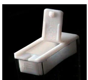
The function of bearing is to allow relative motion between two machine components. In case of simple ball bearing one machine component that is shaft mounted in inner race and other machine component that is bearing housing mounted on outer race. The shaft is rotating member and bearing housing is stationary member. Thus the rotating motion of shaft is not transmitted to bearing housing. In other words it can be said that there is relative motion between two parts. The bearing in which there is relative motion between two part by flexing or bending is nothing but flexure bearing.Typically, flexure bearings are just one part that joins two other parts. A door hinge is an example of flexure bearings.
Fig 1.1 A living hinge (a type of flexure bearing), on the lid of a Tic Tac box.
Both require relative motion to happen to ensure least frictional losses. In flexure bearing one element of bearing surface is allowed to deform on application of load, the surface goes back to its original position on removal of applied load. The deformation of material subjected to condition due to applied load is within the limit of elasticity. This eliminates the wear, vibration and frictional losses. However, the deformation has to be limited. Flexure bearing finds application in precision and micro machining applications and some medical applications having very low relative motion. Flexure bearings are simple and inexpensive. They are usually lightweight and produce a low amount of friction, but their range of motion is limited and
generally can‘t support high loads.
2. LITERATURE REVIEW
As per Phase I final report published by Peckham Engineering and Tool, Manhattan Beach, CA with Phillips Laboratory, Kirtland Air Force Base, New Mexico in the name of ‗Precision Linear Flexure Bearing Cartridge’ on page number 4 typical circular flexure geometries are designed [1].
_____________________________
Fayaz H. Kharadi, Dept. of Mech. Engg. JSCOE,Pune
Mayur S. Jadhav, Dept. of Mech. Engg. JSCOE,Pune
Sachin D. Kanhurkar, Dept. of
Mech.Engg.JSCOE,Pune,[email protected]
Penelope A. Pereira, Dept. of
Mech.Engg.JSCOE,Pune, [email protected] Dr.Virendra K. Bhojwani, Dept. of Mech. Engg.
JSCOE,Pune, [email protected]
INTERNATIONAL JOURNAL OF SCIENTIFIC & TECHNOLOGY RESEARCH VOLUME 4, ISSUE 01, JANUARY 2015 ISSN 2277-8616
171 IJSTR©2015
www.ijstr.org Fig. 2.1 shows different geometries reported for the flexure
bearingby Peckham Engineering and Tool [1].
Fig 2.1 Different geometries of flexure bearing [1]
In the report [1] depending upon the application the geometry of flexure has been suggested.
1. The Oxford/Bae spiral cut flexure diaphragms were fabricated for the application of Oxford/British Aerospace (Bae) cryocooler flexure.
2. The Servoid flexure was a South Bend Controls proprietary configuration.
3. The "Doily Cut" flexure was the standard design used in electrodynamic shakers in the 1970's. 4. The Washington State University (WSU) 2-leg
flexure was developed as part of a Sterling cycle heart pump program.
5. The Tri-radial flexure configuration was an alternate examined as part of this Sterling cycle heart pump 6. Tangential 3-Leg flexure bearing was used for
Aerospace application.
Following criteria has been applied for selection of geometry of flexure design to finalize the most suitable and economical solution.
1. Toensure lowest possible mechanical stresses induced during operation.
2. Ease of manufacturing. 3. Reduce manufacturing cost. 4. Feasibility of Mass production.
5. In the report by Peckham Engineering and Tool [1]several alternative configuration were synthesized & evaluated.
From the above discussion following flexure geometries have been selected for analysis purpose and for convenient suitable names has given depending upon groove cut on the flexure dis
1. 1.Oxford/British Aerospace cryocooler flexure (Helical arms)
2. 2.6 Legs Archimedes spiral (Spiral arms)
3. 3.Tangential 3 legs flexure bearing (Triangular arms)
4. 4.Standard shaker (Staggered arms)
5. 5.With reference to above statement published in the paper one more geometry was studied named 3 Lges Archimedes spiral arm.
3. METHODOLOGY
Analysis of flexure bearing was done in Ansys 14.0 workbench to determine stresses in flexural bearing.
4. CATIA MODEL OF FLEXURE BEARING
The model has created in Catia V5R10 version. The dimensions for creating model has taken as follows.1. The thickness of flexure – 0.3mm 2. The diameter of flexure - 69mm.
3. Holes for clamping along the periphery – 6 mm [2]. These dimensions were common for different geometries. Only type of groove has been changed for all geometries.
INTERNATIONAL JOURNAL OF SCIENTIFIC & TECHNOLOGY RESEARCH VOLUME 4, ISSUE 01, JANUARY 2015 ISSN 2277-8616
172 IJSTR©2015
www.ijstr.org Fig 4.1 Catia model of flexure
Above figure shows the model of triangular flexure created by above procedure. In this way different geometries were created as shown below.
Fig 4.2 Catia model of different flexure
5. ANALYSIS OF FLEXURE BEARING IN
ANSYS
Ansys v 14 is used to calculate equivalent stress by applying different material. Boundary conditions are as follows
1. The thickness of plate taken as 0.3mm[2].
2. As the displacement of the piston in the linear compressor is 5 mm from mean position so displacement was taken 5 mm at the central hole for analysis[3].
3. Material taken as Beryllium Copper [4]. 4. Clamping 12 holes as fix support. 5. Meshing has been done as ―fine‖
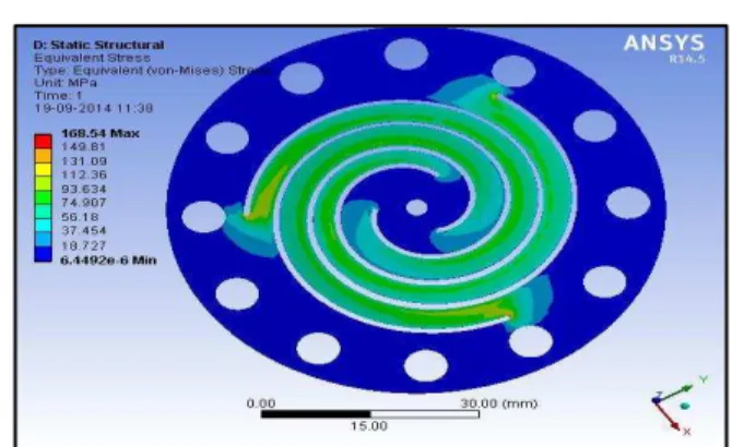
1. Helical arm geometry
Fig.5.1 Ansys model of helical arm geometry
The figure 5.1 shows ansys model of helical arm geometry in which area of maximum stress value that is 168.54MPa and region for maximum stress has shown.
2. Archimedes spiral arm geometry
Fig.5.2 Ansys model of Archimedes spiral arm geometry
Figure 5.2 shows maximum stress which is 773.84MPa and area of maximum stress which is at the end of spiral cut.
3. Tri-angular arm geometry
Fig.5.3 Ansys model of triangular arm geometry
INTERNATIONAL JOURNAL OF SCIENTIFIC & TECHNOLOGY RESEARCH VOLUME 4, ISSUE 01, JANUARY 2015 ISSN 2277-8616
173 IJSTR©2015
www.ijstr.org 4. Staggered arm geometry
Fig.5.4 Ansys model of staggered arm geometry
Figure 5.4 shows maximum stress value of 1023.7MPa and area of maximum stress.
5. 3 Lges Archimedes spiral arm geometry
Fig.5.5 Ansys model of3 Legs Archimedes spiral arm geometry.
Figure 5.5 shows maximum stress value of 1047.50MPa and area of maximum stress induced in the flexure.
5.1 Ansys results.
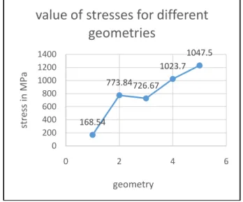
Table 5.1shows different values of equivalent stress for 5 mm displacement and 0.3 thickness for different geometries for beryllium copper.
Graph 1 Geometry vs. Equivalent stress
Above graph clearly indicates the equivalent stress induced in helical arm geometry is 168.54MPa which is minimum in all different geometries
6. CONCLUSION
The analysis has been done for different geometries by keeping thickness, material and deformation constant. From the graph it is clear that helical arm geometry (Geometry No. 1) gives minimum equivalent stress that is 168.54MPa and 3 Legs archimedes spiral arm(Geometry No. 5) givesmaximum equivalent stress that is 1047.5MPa. So optimum design is that design which gives minimum equivalent stress for same deflection. So it is concluded that helical armed geometryis suitable for flexure bearing application.
REFERENCES
[1] Peckham Engineering and Tool, Manhattan Beach, CA with Phillips Laboratory, Kirtland Air Force Base, New Mexico in the name of ―Precision Linear Flexure Bearing Cartridge‖Phase I page number 4.
[2] Saurabh Malpani, Yogesh Yenarkar, Dr. Suhas Deshmukh, S P Tak, D.V. Bhope ―Design OF Flexure Bearing For Linear Compressor by Optimization Procedure Using FEA‖, International Journal of Engineering Science and Technology (IJEST) Vol. 4 No.05 May 2012 pp.1991-1999
[3] A.S. Gaunekar, T. Giiddenhenrich and C. Heiden, ―Finite element analysis and testing of flexure bearing elements‖, cryogenics 1996 volume 36, Number 5, page 359-364
[4] Saurabh Anand Malpani, Yogesh Yenarkar, Suhas Deshmukh ―FE Analysis of Flexural Bearing for LinearCompressor‖, International Journal of Applied Research in Mechanical Engineering, Volume-1, Issue-1, 2011 pp 01-05
168.54
773.84726.67 1023.7
1047.5
0 200 400 600 800 1000 1200 1400
0 2 4 6
stres
s
in
M
Pa
geometry
![Fig 2.1 Different geometries of flexure bearing [1]](https://thumb-eu.123doks.com/thumbv2/123dok_br/18181694.331218/2.918.83.411.142.969/fig-different-geometries-of-flexure-bearing.webp)