THERMOMECHANICAL BEHAVIOUR OF DRY CONTACTS IN DISC
BRAKE ROTOR WITH A GREY CAST IRON COMPOSITION
by
Ali BELHOCINE
*and Mostefa BOUCHETARA
Laboratory of Applied Mechanics, Faculty of Mechanical Engineering, University of Sciences and Technology of Oran, Oran, Algeria
Original scientific paper DOI: 10.2298/TSCI110826141B
The main purpose of this study is to analysis the thermomechanical behavior of the dry contact between the brake disc and pads during the braking phase. The simula-tion strategy is based on the computer code ANSYS11. The modeling of transient temperature field in the disk brake is actually used to identify the factor of geomet-ric design of the disk to install the ventilation system in vehicles. The thermal-struc-tural analysis is then used to couple the deformation established, the von Mises stresses in the disk, and the contact pressure distribution in pads. The results are satisfactory compared to those found in the literature.
Key words: brake discs, heat flux, heat transfer coefficient, von mises stress, contact pressure
Introduction
The braking process is in fact the matter of energy balance. The aim of braking system is to transform mechanical energy of moving vehicle into the some other form, which results by de-creasing of vehicle speed. The kinetic energy is transformed into the thermal energy, by using the dry friction effects and, after that, dissipated into the surroundings [1, 2].
In 2002, Nakatsuji et al. [3] did a study on the initiation of hair-like cracks which formed around small holes in the flange of one-piece discs during overloading conditions. The study showed that thermally induced cyclic stress strongly affects the crack initiation in the brake discs. In order to show the crack initiation mechanism, the temperature distribution at the flange had to be measured. Using the finite element method, the temperature distribution under overloading was analyzed. 3-D unsteady heat transfer analyses were conducted using ANSYS. A 1/8 of the one piece disc was divided into finite elements, and the model had a half thickness due to symmetry in the thickness direction. In 2000, Valvano and Lee [4] did a study on the tech-nique to determine the thermal distortion of a brake rotor. The severe thermal distortion of a brake rotor can affect important brake system characteristics such as the system response and brake judder propensity. As such, the accurate prediction of thermal distortions can help in the designing of a brake disc. In 1997, Hudson and Ruhl [5] did a study on the air flow through the passage of a Chrysler LH platform ventilated brake rotor. Modifications to the production ro-tor’s vent inlet geometry are prototyped and measured in addition to the production rotor. Vent passage air flow is compared to existing correlations. With the aid of Chrysler Corporation, in-vestigation of ventilated brake rotor vane air flow is undertaken. The goal was to measure cur-rent vane air flow and to improve this vane flow to increase brake disc cooling. Rise resulting
from the temperature can strongly influence the properties of surface of materials in slip, support physicochemical and microstructural transformations and modify the rheology of the interfacial elements present in the contact [6]. Recent numerical models, presented to deal with rolling pro-cesses [7, 8] have shown that the thermal gradients can attain important levels which depend on the heat dissipated by friction, the rolling speed, and the heat convection coefficient. Many other works [9, 10] dealt with the evaluation of temperature in solids subjected to frictional heating. The temperature distribution due to friction process necessitates a good knowledge of the con-tact parameters. In fact, the interface is always imperfect – due to the roughness – from a me-chanical and thermal point of view. Recent theoretical and experimental works [11, 12] have been developed to characterise the thermal parameters which govern the heat transfer at the vi-cinity of a sliding interface. In certain industrial applications, the solids are provided with sur-face coating. A recent study has been carried out to analyse the effect of sursur-face coating on the thermal behavior of a solid subjected to friction process [13]. In creased thermal efficiency and the integrity of materials in high-temperature environments is an essential requirement in mo-dem engineering structures in, automotive, aero space, nuclear, offshore, environmental, and other industries. Nowadays, the finite element method is used regularly to obtain numerical so-lutions for heat transfer problems. The most common choice when using finite elements is stan-dard Galerkin formulation [14].
In this work, we will make a modeling of the thermomechanical behavior of the dry contact between the discs of brake pads at the time of braking phase; the strategy of calculation is based on the software Ansys 11 [15]. This last is elaborate mainly for resolution of the com-plex physical problems. The numerical simulation of the coupled transient thermal and stress field is carried out by sequentially thermal-structural coupled method based on Ansys.
Heat flux entering the disc
In the case of disc brake, the effective friction processes between the pads and the disc are extremely complex due to the fact that the present time brake pads, due to their composite structure [16], do not have constant chemical-physic proprieties, the organic contained elements being subject of a series of transformations under the influence of temperature increase. The heat distribution between the brake disc and the friction pads is mostly dependent on material characteristics, among whom a major influence is due to the densityrd,p[kgm–3], the thermal conductivitykd,p[Wm–1K–1], and the specific heatC
d,p[Jkg–1K–1] of the disc’s (indexd) and braking pads materials (indexp), respectively. DenotingQdandQg[J] the heat quantities as-sumed by the disc and the braking pads, respectively, one could be expressed in the following manner [17]:
Q k C
k C
d
p
d d d
p p p
Q =
r r
(1)
Because the braking disc is not entirely covered by the friction pads, within computing we have to consider the ratio between the disc surfaceSdand the pad surfaceSp[mm]. Denoting the ratio of heat’s division between the disk and pads with:
j r
r
c d
p d
p
d d d
p p p d
p
=Q =
Q S S
k C
k C S
S (2)
j j j c C C = + Q 1 (3) j j g C = + Q 1 1 (4)
The brake disk assumes the most part of the heat, usually more than 90% [18], through the effective contact surface of the friction coupling. Consider-ing the complexity of the problem and average data processing limited, one replaced the pads by their effect, represented by an entering heat flux (fig. 1). The initial heat fluxq0entering the disc is calcu-lated by the following formula [19]:
q m vz
A
0 1
2 2
= -F g
dep
(5)
wherez=a/g is the braking effectiveness,a– the deceleration of the vehicle [ms–2],f– the rate distri-bution of the braking forces between the front and rear axle,Ad– the disc surface swept by a brake pad [m2],n
0– the initial speed of the vehicle [ms–1],ep–
the factor load distribution on the surface of the disc,m– the mass of the vehicle [kg], and g – the acceleration of gravity [ms–2].
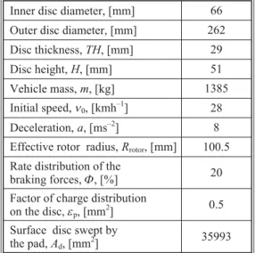
The loading corresponds to the heat flux on the disc surface. The dimensions and the parameters used in the thermal calculation are recapitulated in tab. 1.
The disc material is gray cast iron with high carbon content [20], with a good thermophysical characteristics and the brake pad has an isotropic elastic behavior whose thermomechanical characteristics adopted in this simulation of the two parts are recapitulated in tab 2.
Figure 1. Application of flux
Table 1. Geometrical dimensions and application parameters of automotive braking
Inner disc diameter, [mm] 66
Outer disc diameter, [mm] 262
Disc thickness,TH, [mm] 29
Disc height,H, [mm] 51
Vehicle mass,m, [kg] 1385
Initial speed,n0, [kmh–1] 28
Deceleration,a, [ms–2] 8
Effective rotor radius,Rrotor, [mm] 100.5
Rate distribution of the
braking forces,F, [%] 20 Factor of charge distribution
on the disc,ep, [mm2]
0.5
Surface disc swept by the pad,Ad, [mm2]
35993
Table 2.Thermoelastic properties used in simulation
Material properties Pad Disc
Thermal conductivity,k,
[Wm–1°C–1] 5 57
Density,r,[kgm–3] 1400 7250 Specific heatc, [Jkg–1°C–1] 1000 460
Poisson ratio,n 0.25 0.28 Thermal expansion,a,
[10–6per °C] 10 10,85
Elastic modulus,E, [GPa] 1 138
Coefficient of friction,m 0.2 0.2 Operation conditions
Angular velocity,w,
[rads–1] 157.89
Hydraulic pressure,P,
Thermal analysis of the problem
The transient heat conduction in 3-D heat transfer problem is governed by the
fol-lowing differential equation [21]:
– ¶ ¶ ¶ ¶ ¶ ¶ ¶ 
q q q
Q C T
x y z
x + y + z t
æ è ç ç ö ø ÷
÷+ =r p (6)
whereqx,qy, andqzare the conduction heat fluxes in the x-, y-, and z-directions, respectively,Cp
is the specific heat,r– the specific mass,Q– the internal heat generation rate per unit volume, andT– the temperature that varies with the co-ordinates as well as the timet. The conduction heat fluxes can be written in the form of temperature using Fourier’s law. Assuming constant and uniform thermal properties, the relations are:
q k T
x q k
T y
q k T
z
x x y y
z z = -¢ = - ¢ = -¶ ¶ ¶ ¶ ¶ ¶ , , (7)
wherekx,ky, andkzare the thermal conductivity in the x-, y-, and z-directions, respectively. The heat transfer boundary conditions consist of several heat transfer modes that can be written in different forms. The boundary conditions frequently encountered are as follows [22, 23]:
Ts =T x y z t1( , , , ) (8)
-qs =h T( s -T )
4 (9)
whereT1is the specified surface temperature,qs– the specified surface heat flux (positive into a surface),h– the convective heat transfer coefficient,Ts– the unknown surface temperature, and
T4– the convective exchange temperature.
Modeling in ANSYS CFX
The finite volume method consists of three stages; the formal integration of the gov-erning equations of the fluid flow over all the (finite) control volumes of the solution domain. Then discretisation, involving the substitution of a variety of finite-difference-type approxima-tions for the terms in the integrated equation representing flow processes such as convection, diffusion, and sources. This converts the inte-gral equation into a system of algebraic equa-tions, which can then be solved using iterative methods [24]. The first stage of the process, the control volume integration, is the step that dis-tinguishes the finite volume method from other computational fluid dynamics (CFD) methods. The statements resulting from this step express the “exact” conservation of the relevant proper-ties for each finite cell volume. This gives a clear relationship between the numerical ana-logue and the principle governing the flow.
To enable the modeling of a rotating body (in this case the disc) the code employs the rotat-ing reference frame technique. The solution
scheme employees thek-emodel with scalable wall function and sequential load steps. For the preparation of the mesh of CFD model, one defines initially, various surfaces of the disc in ICEM CFD as fig. 2 shows it, we used a linear tetrahedral element with 30717 nodes and 179798 elements. In order not to weigh down calculation, an irregular mesh is used in which the meshs are broader where the gradients are weaker (not-uniform mesh), (fig. 3).
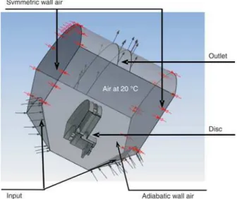
The CFD models were constructed and were solved using ANSYS-CFX software package [25]. The models employ periodic boundary conditions on the segmented sides; and the radial and axial lengths of the air domain surrounding the disc. The disc is modeled attached to an adiabatic shaft whose axial length spans that of the domain. The air around the disc is consid-ered atT
4= 20 ° C and open boundaries with zero relative pressure were used for the upper,
lower and radial ends of the domain (fig. 4).
The values of the exchange coefficient will be taken average values calculated by the mini-mal and maximum values obtained using ANSYS CFX POST as it east indicates in fig. 5.
Results of convection heat transfer coefficient h
When the temperature rises above that of the passing air, some of the frictional heat goes out into the air by the phenomena of radiation and convection, some is conducted into the hub and a pad, and the rest of the heat is stored within the disc rotor. Generally, the major portion of the generated heat flows out into the air. It is there-fore important to determine the convective heat transfer coefficients. It is very difficult to
deter-Figure 3. Irregular mesh in the wall (for color image see journal websiteFigure 4. Brake disc CFD model)
Figure 5. Distribution of heat transfer coefficient on a ventilated disc in the stationary case (gray cast iron FG 15)
mine the convection heat transfer coefficients of the brake disc accurately during the braking process: these are dependent on the shape of the brake system and the air flow conditions (lami-nar, turbulent, or transition flow). The convective heat transfer coefficients of the solid disc brake are quoted from the experiential formulas by Limpert [26, 27].
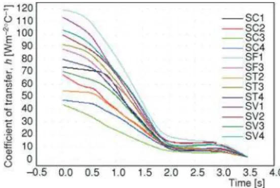
In order to accurately determine brake temperatures at a particular time (t) in the brak-ing phase, knowledge of the heat transfer coefficient is required. The heat transfer coefficient (h) will depend on the airflow in the region of the brake rotor, and the vehicle speed. Figures 6 and 7 give the variation of exchange coefficient (h) for various surfaces components the full and venti-lated disc, respectively. One then obtains beams of curves in the transitory mode of flow having the same form and decrease about the braking time (t= 3.5 s). One observes that in the case of ventilated disc, the values ofhare large that of the full disc what characterizes the fast model of cooling.
The comparison between figs. 6 and 7 concerning the variation of heat transfer coeffi-cient in the non-stationary mode for the two types of design of the full and ventilated disc, one notes that the introduction of the ventilation system influences directly the value of this coeffi-cient for same surface what is logically significant because this mode of ventilation intervenes in the reduction in the difference in temperature wall-fluid.
Meshing of the disc
The elements used for the mesh of the full and ventilated disc are tetrahe-dral 3-D elements with 10 nodes (isoparametric) (fig. 8).
Initial and boundary conditions
The boundary conditions are in-troduced into module ANSYS Work-bench [Multiphysics], by choosing the mode of simulation first of all
Figure 6. Variation of heat transfer coefficient (h) of various surfaces for a full disc in the non
stationary case (gray cast iron FG 15) (for color image see journal website)
Figure 7. Variation of heat transfer coefficient (h) of various surfaces for a ventilated disc in
transient case (gray cast iron FG 15) (for color image see journal website)
(permanent or transitory), and by defining the physical properties of materials. These conditions constitute the initial conditions of our simulation. After having fixed these parameters, one in-troduces a boundary condition associated with each surface:
– total time of simulation = 45 s, – increment of initial time = 0.25 s,
– increment of minimal initial time = 0.125 s, – increment of maximal initial time = 0.5 s, – initial temperature of the disc = 60 °C, – materials: grey cast iron (FG15),
– convection: one introduces the values of heat transfer coefficient (h) obtained for each surface in the shape of a curve (figs. 6 and 7), and
– flow one introduces the values obtained of flow entering by code CFX.
Results and discussions
Influence of construction of the disc
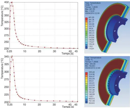
Figure 9 shows the variation in the temperature according to time during a simulation. From the first step, the variation in the temperature shows a great growth which is due to the speed of the physical course of phenomenon during a braking phase, namely friction, plastic mi-cro distortion of contact surfaces.
For the full disc, the temperature reaches its maximum value of 401.55 °C at the mo-mentt= 1,8839 s, then it falls quickly to 4.9293 s, as of this moment and until the end time of simulation (t= 45 s) , the variation in the temperature becomes slow. It is noted that the interval [0-3.5 s] represents the phase of forced convection. From the latter, one is in the case of the free convection until the end of the simulation. In the case of ventilated disc, one observes that the temperature of the falls disc approximately 60 °C compared to the first case. It is noted that the ventilation in the design of the disc brake gives a better system of cooling.
Coupled thermo-mechanical analysis
FE model and boundary conditions
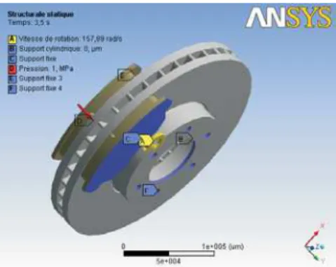
A commercial front disc brake system consists of a rotor that rotates about the axis of a wheel, a caliper piston assembly where the piston slides inside the caliper, which is mounted to the vehicle suspension system, and a pair of brake pads. When hydraulic pressure is applied, the piston is pushed forward to press the inner pad against the disc and simultaneously the outer pad is pressed by the caliper against the disc [28]. The numerical simulations using the ANSYS fi-nite element software package were performed in this study for a simplified version of a disc brake system which consists of the two main components contributing to squeal the disc and the pads. The various boundary conditions in embed-ded configurations are imposed on the model (disc-pad), taking into account its environment (the simple case is shown in fig. 10). The initial temper-atures of the disc and the pads are 20 °C and the surface convection condition is applied at all sur-faces of the disc with the values of the heat transfer coefficient calculated previously – the convection coefficient (h) of 5 W/m2°C is applied at the sur-face of the two pads. The heat flux into the brake disc during a braking process can be calculated by the formula described in the first part. The finite el-ement mesh is generated using 3-D tetrahedral ele-ment with 10 nodes (solid 187) for the disc and brake pads. There are about 185901 nodes and 113367 elements are used (fig. 11). The thermal coupling will be carried out by the thermal condi-tion at a temperature non-uniform all takes the ther-mal environment of the model of it, for this reason, the order “ thermal condition ” will be used to deal with the thermomechanical coupled problem and to manage the transient state.
Thermal deformation
Figure 12 gives the distribution of the total dis-tortion in the whole (disc-pads) for various mo-ments of simulation. For this figure, the scale of de-formation values varies from 0mm to 284,55mm. The value of maximum displacement recorded dur-ing this simulation is at the momentt= 3.5 s which
Figure 10. Boundary conditions and loading imposed on the disc-pads
(for color image see journal website)
corresponds to the braking time. One observes a strong distribution which increases with time on the friction tracks and the crown external and the cooling fins of the disc. Indeed, during a braking, the maximum temperature depends almost entirely on the storage capacity of heat of disc (on particular tracks of friction) this deformation will generate a dissymmetry of the disc following the rise of temperature what will cause a deformation in the shape of an umbrella.
Von Mises stress distribution
Figure 13 presents the von Mises stress distribution to various moments of simulation, the scale of values varies from 0 MPa to 495.56 MPa. The maximum value recorded during this simulation of the thermomechanical coupling is very significant. One observes a strong con-straint on the level of the bowl of the disc. Indeed, this disc is fixed to the hub of the wheel by screws preventing its movement, and in the presence of the rotation of the disc, torsional stress and sheers generated at the level of the bowl are able to create the stress concentrations and rup-ture of the bowl of disc.
Contact pressure
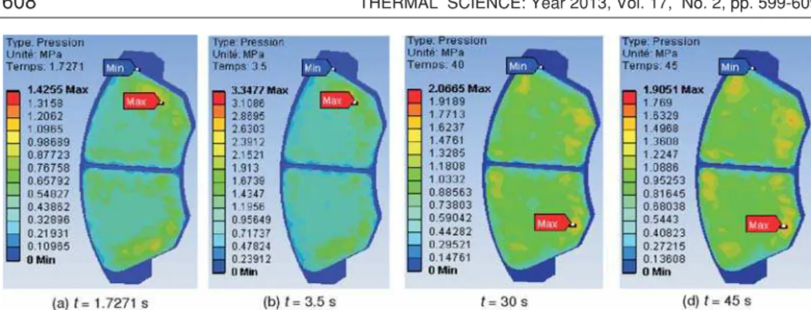
Figure 14 shows the contact pressure distribution in the friction interface of the inner pad taken for at various times of simulation. For this distribution the scale varies from 0 MPa to 3.3477 MPa and reached a value of pressure at the momentt= 3.5 s which corresponds to the null rotational speed. It is also noticed that the maximum contact pressure is located on the edges of the pad of the entry and goes down towards the exit from the area from friction. This pressure distribution is almost symmetrical compared to the groove and it has the same tendency as that of the distribution of the temperature because the highest area of the pressure is located in the same sectors. Indeed, at the time of the thermomechanical coupling 3d, the pressure carries out
Figure 12. Total distortion distribution (for color image see journal website)
to lead to the not-axisymmetric field of the temperature. This last affects thermal dilation and leads to a variation of the contact pressure distribution.
Conclusions
In this publication, we presented the thermomechanical behavior analysis of the dry contact between the disc and brake pads during the braking process; the modeling is based on the ANSYS software 11.0. We have shown that the ventilation system plays an important role in cooling disks and provides a good high temperature resistance.
The analysis results showed that, a temperature and stress fields in the braking process phase of were fully coupled. The temperature, the von Mises stress and the total deformations of the disc and the contact pressure distribution in the pads increases as the thermal stresses are ad-ditional to mechanical stress which causes the crack propagation and fracture of the bowl and wear of the disc and brake pads. Regarding the calculation results, we can say that they are satis-factory commonly found in the literature investigations. It would be interesting to solve the thermo-mechanical problem of disc brakes with an experimental study to validate the numerical results.
References
[1] Milenkovi}, P. D.,et al., The Influence of Brake Pads Thermal Conductivity on Passenger Car Brake
Sys-tem Efficiency,Thermal Science, 14(2010), Suppl., pp. S221-S230
[2] Belghazi, H., Analytical Solution of Unsteady Heat Conduction in a Two-Layered Material in Imperfect Contact Subjected to a Moving Heat Source, Ph. D. thesis, University of Limoges, Limoges, France, 2010 [3] Nakatsuji, T.,et al., Study on Crack Initiation at Small Holes of One- piece Brake Discs, SAE paper
2002-01-0926, 2002
[4] Valvano, T., Lee, K., An Analytical Method to Predict Thermal Distortion of a Brake Rotor, SAE paper 2000-01-0445, 2000
[5] Hudson, M. D., Ruhl, R. L., Ventilated Brake Rotor Air Flow Investigation, SAE paper pp. 1997-01-033, 1997
[6] Denape, J., Laraqi, N., Thermal Aspect of Friction: Experimental Evidence and Modeling (in French),
Mecanique & Industries, 1(2000), 6, pp. 563-579
[7] Hamraoui, M., Thermal Behaviour of Rollers during the Rolling Process,Applied Thermal Engineering, 29(2009), 11-12, pp. 2386-2390
[8] Hamraoui, M., Zouaoui, Z., Modelling of Heat Transfer between Two Rollers in Dry Friction, Interna-tional Journal of Thermal Sciences, 48(2009), 6, pp. 1243-1246
[9] Laraqi, N., Velocity and Relative Contact Size Effect on the Thermal Constriction Resistance in Sliding Solids,ASME J. Heat Transfer, 119(1997), 1, pp. 173-177
[10] Yapici, H.,et al., Transient Temperature and Thermal Stress Distributions in a Hollow Disk Subjected to a Moving Uniform Heat Source,Journal of Thermal Stress, 31(2008), 5, pp. 476-493
[11] Laraqi, N.,et al., Temperature and Division of Heat in a Pin-on-Disc Frictional Device – Exact Analytical Solution,Wear, 266(2009), 7-8, pp. 765-770
[12] Bauzin, J. G., Laraqi, N., Simultaneous Estimation of Frictional Heat Flux and Two Thermal Contact Pa-rameters for Sliding Solids,Numerical Heat Transfer, 45(2004), 4, pp. 313-328
[13] Barii, A.,et al., Effect of Thickness and Thermal Properties of Film on the Thermal Behavior of Moving Rough Interfaces,European Physical Journal – Applied Physics, 26(2004), 1, pp. 29-34
[14] Mijuca, D. M.,et al., A New Multifield Finite Element Method in Steady State Heat Analysis,Thermal Science, 9(2005), 1, pp. 111-130
[15] Zhang, L.,et al., Simulation and Analysis of Thermal Fatigue Based on Imperfection Model of Brake Discs, Beijing Jiaotong University,Proceedings Appl. Math. Mech., 9(2009), 1,pp. 533-534
[16] ***, Fiche U. I. C . 541-3: Brake Disks and Brake Disc Pads (in French), 4thed., 1993
[17] Saumweber, E.,Temperature Calculation of Brake Disc for Different Driving Programs (in German),
Leichtbau der Verkehrsfahrzeuge, 13 (1969), 3
[18] Cruceanu, C.,Brakes for Railway Vehicles(in Romanian), Matrixrom, Bucuresti, 2007, ISBN 978-973-755-200-6
[19] Reimpel, J., Brake Technology (in French), Vogel Verlag, Würzburg, Germany, 1998
[20] Gotowicki, P. F., Numerical and Experimental Analysis of a Pegs-Wing Ventilated Disk Brake Rotor, with Pads and Cylinders, 10thEAEC European Automotive Congress – Paper EAEC05YUAS04 – P 5, Belgrade, 2005
[21] Yu, H.,et al., Study on Temperature Distribution Due to Freezing and Thawing at the Fengman Concrete Gravity Dam,Thermal Science,15(2011), Suppl. 1, pp. S27-S32
[22] Sergerlind, L. J.,Applied Finite Element Analysis, John Wiley and Sons, New York, USA, 1984 [23] Hinton, E., Owen, D. R. J.,An Introduction to Finite Element Computations, Pineridge Press Limited,
London, 1981
[24] Versteeg, H. K., Malalasekera, W.,An Introduction to Computational Fluid Dinamics, The Finite Volume Method, 2ed, Longman Scientific, UK
[25] ***, Ansys v.11 User’Manual Guide
[26] Arpaci,V. S.Conduction Heat Transfer, Ginn Press, Nedham Heights, Mass., USA, 1991
[27] Limpert, R. Thermal Analysis of Friction Brakes, Brake Design and Safety, ch. 3, Science of Automotive Engineers Inc,Warrendale, Penn., 1992
[28] Nouby, M., Srinivasan, K., Parametric Studies of Disc Brake Squeal Using Finite Element Approach, In-dia,Jurnal Mekanikal, (2009), 29, pp. 52-66