Conception of Electro-Stimulation System
Adil Salbi #1, Seddik Bri #2
# Materials and Instrumentations (MIN), Department of Electric Engineering,
ESTM - University of Moulay Ismail – Meknes - MOROCCO
1 [email protected] 2 [email protected]
Abstract— The aim of this work is to suggest a reliable solution of electro-stimulation making it possible to restore defective functions of the nervous systems among certain patients. This solution consists in creating a signal similar to that arriving of the central nervous system. Thus, work presented aims to design an electronic circuit of stimulation allowing the contraction of the muscle to restore its function by a biphasic train of electric impulse. This stimulator system is composed of a clock, an inverter and a logical sequencer which shifts the clock signal. The stage of power makes it possible to adapt the signals newcomers on a transformer booster coupled to a stage of order to regulate the amplitude of the impulse.
Keyword-Electronic, Stimulation, Electric Impulsion, Stimulator, Nervous System I. INTRODUCTION
In the daily life, everyone is likely to have a failure on the level of the sensorimotor system continuation of a disease or an accident. Two situations generally arise: medullar lesions (spinal-cord) and lesions of the brain which involves dysfunctions of organs of the body [1 – 4].
At the time of an incomplete paralysis, certain residual functions are preserved; functional rehabilitation is then imaginable in the case of electrotherapy for the maintenance and the recovery of a maximum of functions. Being given that the private muscles of their innervations undergo a progressive atrophy, but can recover if they are innervated [3]. More than muscles damages, electrotherapy in the form of functional electric stimulation (FES) can be used in the sporting world at the time of body building training by the athletes [5 – 7].
In this article, we present the design of an electric system of stimulation based on the electric generation of two signals by a circuit ordered in amplitude.
II. THEORY OF ELECTRO-STIMULATION
Electrotherapy indicates the whole uses of the electric current for the treatment of the diseases. This art aims to exploit the properties of the nervous system, known since 1789 when Luigi Galvani observed that the muscles of the thigh of a frog contracted when the nerve innervating them was put in contact with metal. Therefore, a technological way makes it possible to restore or compensate certain defective functions of the sensorimotor system: it is the electric stimulation. It has already shown great successes as in the case of pacemaker, making it possible to control the rhythm of the beats of the heart, the cochlear implants restoring hearing, or even more recently of the implants “brain deep” aiming at removing shakings in the Parkinson's disease [3], [8].
In order to understand the operation of the various types of current used by the clinicians and the physiotherapists, it is important to describe their characteristics [9]. There exist two types of currents: the alternative current (AC), biphasic and the direct currents (DC), monophasic.
They can be continuous or pulsatile. The monophasic currents are polarized (they circulate only between negative and positive electrodes) while the biphasic currents have a polarity which is reversed permanently. Thus, the effects of polarity are minimized or eliminated with the biphasic current the thing which reduces the risks of cutaneous burns or mucosal in cavitary [4], [10].
An electric system of stimulation comprises an energy source, a generating electronic circuit of electric stimuli and electrodes. The two electrodes are placed on the path of the motor nerve target engine or close to the motor drive plate or item, where the nervous fibers are connected to muscle fibers. In general, two techniques of the FES were developed, namely (i) external stimulation with electrodes placed on the skin of the patient and (ii) an internal stimulation with surgically implanted electrodes. [3], [11].
III.SYSTEM OF FUNCTIONAL OF ELECTRIC SIMULATION
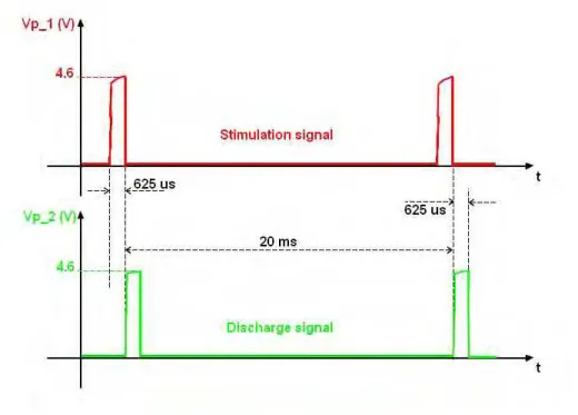
The basic principle of the system of functional electrical stimulation put back on the generation of more or less broad impulses and quite specific frequency (fig. 1). The average value of the signal is always null, which avoids a habituation of the muscle, an undesirable cutaneous ionization or a polarization of the metal prostheses.
Fig. 1. The shape of electrical signal of functional stimulation
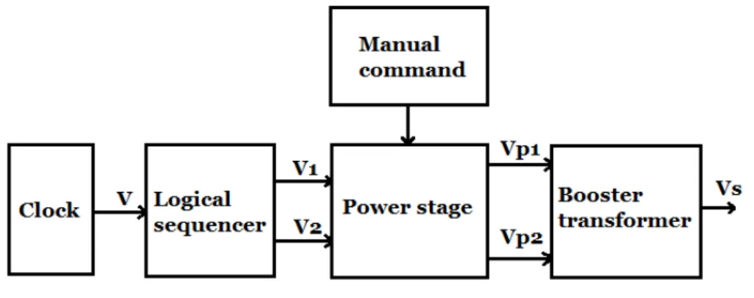
The synoptic diagram of the system is presented on the following figure (fig. 2):
Fig. 2. Block diagram of the electrical stimulator
By exploiting the properties of circuit NE555 in its astable mode, and by adding a logical reverser on its exit, we can handle very well the signal clock in frequency like in width of impulse and especially with cyclic report
= very small (see fig. 1 formerly). In this case we will have: - The duration of impulse is = , × ×
- The Period of the signal is = , × × ×
We will take = and = . to have 625 µs like duration of impulse and 20 ms like period, it is necessary that resistances R1 and R2 carry out the following values:
= , × .. − × = Ω
= , × .. = Ω
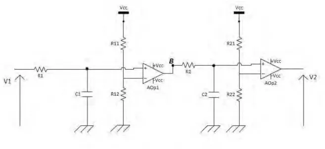
Fig. 3. Logical Sequencer
The operation of the circuit is as follows: V1 attacks the sequencer and when V1 is in a high state the C1 condenser is charging through R1 resistance, and when the load of the condenser reaches V–, we have the swing
of the first AOp1 amplifier to a high state, the time of load of the condenser is thoroughly regulated by R1 resistance in such way to reach V– with half rise time of V1, the condenser will continue to charging during
other half of the rise time until V1 fall to zero. Where the discharge of the condenser will start, since the constant load is the same for the discharge, the tension of the condenser will decrease until reaching V– at a time
equal to half rise time.
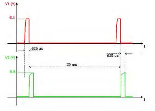
On the outlet side of the AOp2 amplifier, we have a V2 signal identical to that of the point B but shifted in the time of 312.5 µs, and thus the V2 signal is shifted of 625 µs versus V1 (fig. 4).
Fig. 4. Voltages V1 and V2
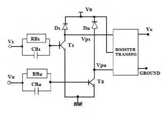
The purpose of the power stage is to adapt the power of V1 and V2 to that required to inject with the transformer. The diagram of the assembly is presented on fig. 5.
Fig. 5. Schema of the output stage
In the assembly of fig. 5, we note that each half coil of the transformer can be regarded as the impedance of collector of each transistor. Therefore, when V1 or V2 is in a high state, that causes the saturation of the one of the transistors; putting, thereby, a half coil to ground, and so on. That produces on the outlet side of the transformer a signal of Vs stimulation of worthless average value and period of 20 ms. The output voltage Vs of the transformer is according to the report of transformation ratio η and the VB tension:
= × −
To adjust the amplitude of Vs, it suffices to vary VB. The Vs tension of stimulation depends directly on VB.
Therefore, if we act on VB, implicitly we act on Vs. Thus, we propose the following command assembly (fig. 6):
Fig. 6. Circuit of manual command
Using the potentiometer, the tension V+, and according to the properties of the amplifier operational, equal to
V–, therefore equal to V
B, which implies that any variation of V+ is transmitted directly to VB, and the output
IV.RESULTS
In this part we will exhibit appearance of simulation and those of experiments for the two successive signals given by the floor clock-sequencer and also the output signals of the power stage. Fig. 7 presents the output V1 of the clock, and V2 output from the sequencer, during a simulation on Orcad-Pspice.
Fig. 7. Simulating signals v1 and v2
We notice well that V2 is delayed of V1 by 625 customs and they have both one period = . Except that the amplitude of the real results (Fig. 8), which is about 6.4 V, are attenuated compared to those of simulation.
In experiments, we obtained at exit of the clock an impulse of amplitude equal to 6.4 V, even as by 9V. Then, we interacted on the exit of the sequencer, by adding a potentiometer, to have the amplitude of V2 as same as V1.
Fig. 8. Graph of the measurements of voltages V1 and V2
The signals V1 and V2 obtained on this stage are to order the transistors of the power stage. The transistor used (2N1117) requires a tension from approximately 1 volt on its basis to function, but the amplitude of V1 and V2 is sufficiently large, is about 6.4 V. the attenuation seen on the level of the clock does not affect the
following stage. For the output of the stage of power, the potential differences at the boundaries of the two primary reels are represented in fig. 9 hereafter.
Fig. 9. Potentials differences of VB-VP_1 and VB-VP_2
Fig. 10. Measures of the output of the power stage
The results obtained by either simulation or experience (see Fig. 10) are very compatible on the shape of the signal as well as on frequency (20 ms). The amplitude “A” of the two signals is set by the voltage VB at the
stage of manual command.
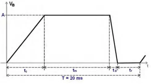
Fig. 11. Shape of signal of the manual command
In the figure above, we have tc, tm, td and tr correspond respectively to contraction, maintain, relaxation and rest periods of the muscle. The amplitude A of VB can reach 8 V, Then, the output signal Vs can reach 80 V,
because we have the transformation ratio = .
When we adjust VB in amplitude at = we obtained:
= ; = . ; = . ; =
The figure 12 shows the overall pattern of the electric system of stimulation that we designed on the software of simulation Pspice. In this simulation, we had to change the values of certain components. For example, we changed the time of load and discharge of the condenser by adjusting the corresponding resistors to achieve the goal of the sequencer in this system which is the shift of V2 on V1 of 625 µs.
Fig. 12. Overall pattern of the electric stimulator
V. CONCLUSION
Technological development tends to improve our daily life, and the technique of electric stimulation is part of this development. This technique aims to restore or rehabilitate certain motor functions of the nervous system via a sequence of well-defined electrical pulses. Our work consists in conceiving an electronic system that materializes this technique. This system generates a sequence of pulses adjustable in amplitude and which has a worthless median value. The principle is based on the generation of two successive impulses, and is shifted in the time of 625 µs, by using timer NE555 followed by a logical sequencer. These two impulses undergo an adaptation in power in the stage of power connected to the transformer booster. This last stage makes it possible to regulate the amplitude of its exit by manual command. Finally, on the outlet side of the transformer, we obtain a biphasic signal of stimulation which has a 50 Hz as frequency and 625 µs the duration of each phase.
REFERENCES
[1] Bri, S., & Zenkouar, L. (s. d.). Conception and Realization of the Manual and Programmable Command of Stimulating Electric
Muscular. Session 4P2a Transient Effects in Electromagnetic Pulse Propagation, 455, 2008.
[2] D. Guiraud, T. Stieglitz, K. P. Koch, J.-L. Divoux, et P. Rabischong, « An implantable neuroprosthesis for standing and walking in
paraplegia: 5-year patient follow-up », J. Neural Eng., vol. 3, no 4, p. 268‑275, December. 2006.
[3] S. Roche, « La stimulation électrique au service du corps », Interstices, 16-mars-2011. [En ligne]. Disponible sur:
https://interstices.info/stimulation-corps.
[4] F. Crépon, Électrothérapie et physiothérapie: Applications en rééducation et réadaptation. Elsevier Masson, 2012.
[5] G. Y. Millet et R. Lepers, « Alterations of neuromuscular function after prolonged running, cycling and skiing exercises », Sports Med.
Auckl. NZ, vol. 34, no 2, p. 105.. 116, 2004.
[6] G. Millet et S. Perrey, Physiologie de l’Exercice Musculaire Licences STAPS Educateurs Sportifs. Paris: Ellipses Marketing, 2005.
[7] A. Barnett, « Using recovery modalities between training sessions in elite athletes: does it help? », Sports Med. Auckl. NZ, vol. 36, no
9, p. 781.. 796, 2006.
[8] Christine Azevedo Coste, « La stimulation électrique pour restaurer des fonctions posturales ». [En ligne]. Disponible sur:
http://serpico.rennes.inria.fr/lib/exe/fetch.php?media=people:phellier:docsciences-christine.pdf.
[9] D. Thomas, « La stimulation électrique fonctionnelle, appareillage et technique de facilitation, D.Thomas A. Killésith 1978.5.437.. 447
», www.kinedoc.org.
[10] P. Decherchi, E. Dousset, T. Marqueste, F. Berthelin, F. Hug, Y. Jammes, et L. Grélot, « Électromyostimulation et récupération
fonctionnelle d’un muscle dénervé », Sci. Sports, vol. 18, no 5, pp. 253.. 263, oct. 2003.
[11] J.-D. Techer, S. Bernard, Y. Bertrand, G. Cathebras, et D. Guiraud, « New implantable stimulator for the FES of paralyzed muscles »,