A R C H I V E S
o f
F O U N D R Y E N G I N E E R I N G
Published quarterly as the organ of the Foundry Commission of the Polish Academy of Sciences
ISSN (1897-3310) Volume 13 Issue 1/2013
125 – 130
24/1
Modeling of Two-Stage Solidification: Part
II Computational Verification of the Model
O. Wodo
a, E.
Gawrońska
b*
aMechanical Engineering Department, Iowa State University, Ames, Iowa, USA
b
Faculty of Mechanical Engineering and Computer Science, Czestochowa University of Technology, Poland *Corresponding author. E-mail address: [email protected]
Received 03.07.2012; accepted in revised form 04.09.2012
Abstract
In Part I of this article, two-stage solidification model was presented. In this part we use our model to simulate solidification of the Al 7% Si alloy for two cooling rates ⁄ and ⁄ . Simulations have been performed for two eutectic transformation modes, typical for modified and unmodified alloys. Obtained cooling curves are qualitatively consistent with the typical cooling curves for modified and unmodified alloys. Moreover, evolution of cooling-curve characteristics is compared with the analytical model and found to be in close agreement.
Keywords: Cellular automata, Solidification, Microstructure modeling, Dendritic structure, Eutectic structure
1. Introduction
Modeling of hypoeutectic alloys solidification is a complex problem, because increase of solid phase fraction is triggered by constitution of two structures: In the first stage, between eutectic and liquidus temperature, dendritic grains nucleate and grow. In the second stage, below eutectic temperature, eutectic structures form. In the latter stage eutectic grains nucleate and grow from the liquid phase that did not solidify in the first stage. As has been reported recently [1-8], various modes of eutectic transformation can be observed, depending on the alloy modifications. In unmodified alloys, eutectic grains nucleate in adjacency of dendritic grains. Whereas, in modified alloys (e.g. by adding strontium modifier) eutectic grains nucleate with no relation to dendritic structure, and the number of eutectic grains is smaller compared to the unmodified alloys.
The eutectic formation is the final stage of the hypoeutectic alloys solidification process, and hence the mode of eutectic transformation can modulate occurrence of defects as has been shown in [1, 4, 7]. Consequently, model that would accurately
capture various modes of eutectic transformation can contribute to better prediction of defects (e.g. porosity or hot-tearing) in castings. The above observation is the main motivation for current work.
The objective of this part of the paper is to verify the two-stage solidification model, presented in Part I. We provide a comparison between two eutectic structure formation modes, in terms of the final microstructure and cooling curves. We discuss the effect of the various impingement schemes, which are related to eutectic transformation mode, on the simulated microstructure and on numerical cooling curve. In addition, we compare the cooling curves generated by the model to those described by analytical model.
2. Computational problem
an element we generate mesh of cellular automata cells. Coupling of computation between those two levels is exploited in
macro-micro models and is called CAFE [9-11].
Table 1.
The quantitative results for predicted microstructure for two eutectic solidification modes – s1 corresponds to nucleation of independent (from dendritic grains) eutectic grains, s2 corresponds to nucleation of eutectic grains in adjacency of dendritic grains. (n is the number of dendritic/eutectic grains in the specimen, �� is the average dendritic/eutectic grain radius for the specimen, f is the fraction of extradendritic fraction, and fi is the fraction of intradendritic eutectic)
�̇ [ �⁄ ] s � � �� � � �� f fi
-2 s1 12 323 12 255.3 0.244 0.390
s2 192 63.8
-20 s1 27 229 27 170.2 0.135 0.479
s2 410 43.6
To solve the diffusion equation occurring in the first stage of the solidification process, i.e. dendritic structure formation, we employ explicit scheme of time integration. This restricts the size of time step ∆, to guarantee stability of the scheme. Additional restriction is introduced to ensure that the increase of envelope radius in a single time step is no larger than 0.2 of cell size:
t = min . ∙2 , ∙
ax , (1)
where is the solute diffusion in liquid, is the size of CA-cell, and is the maximum velocity in the previous time step. The dendritic nucleation density has been correlated with the cooling rate at the beginning of solidification ̇ by the following parabolic function:
= ∙ ̇ , (2)
where coefficients and are set as proposed in [12]. We converted the nucleation density into two dimensional density using stereological Equation (3):
= √ ⁄ ∙ ⁄ (3)
In the work we assume that the first stage of solidification is the same for both modified and unmodified alloys. Thus, the same dendritic nucleation density is used in both cases. However, we should keep in mind that modifier may affect the dendritic structure formation. In the second stage of the solidification, the nucleation process unfolds in slightly different way, depending on the eutectic transformation mode. In such case nucleation phenomena depends on different densities and different algorithms, as explained in Part I. The authors of the series of papers [3, 6, 7] investigated solidification of modified and unmodified hypoeutectic alloys, and indicated that the difference in nucleation densities for eutectic structure must exists. In [6] McDonald et al. claim that the difference in nucleation density
and the size of eutectic grains is “drastic”. It should be noted, that
due to the fact that eutectic transformation modes are relatively new area of research, only limited experimental data is available. Keeping this in mind, in our approach we assumed that in the case of modified alloys the nucleation density for eutectic structure is the same as for the dendritic structure. In turn, for the second
mode, which is typical for unmodified alloys, we assumed that in the adjacency of each main dendritic arm four eutectic grains nucleate. The number of nucleating grains and their average size have been summarized in Table 1. In addition, following [12] we introduced different growth coefficients to describe modified and unmodified alloys, μ = 3.5 ∙ 1 − m ∙ ⁄ , μ =
1 − m ∙ ⁄ , respectively.
3. Results and discussion
All results presented in the paper have been obtained for hypoeutectic binary alloy, i.e. Al-7%Si alloy. The eutectic fraction in this alloy is significant, and is more than 50%. Corresponding thermophysical parameters are (after [13]): the volumetric specific heat ρc = .35 ∙ 1 J/ m , the latent heat
L = 9.5 ∙ 1 J/m, the solute diffusion coefficient = 3 ∙
1 − m / , the Gibbs-Thomson coefficient = .9 ∙ 1 − ∙ �, the melting temperature of pure Al = ℃, the slope of the liquidus line m = 7.7 /%, the solute partitioning coefficient k = .117, the eutectic temperature = 577℃, and the eutectic concentration c = 1 .77. We performed a set of simulations for two macroscopic elements of size . ×
. m and CA-cell size of 1 − m. All simulations have been
performed for two cooling rates, typical for different parts of a casting: ⁄ typical for the central part of a casting, and
⁄ typical for elements close to a mould.
Grain Structure Simulation of Al-7%Si Alloy
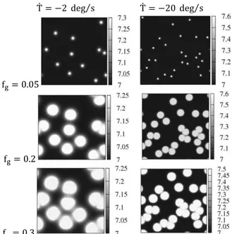
As we have already mentioned, the first stage is identical for both eutectic transformation modes. When the temperature drops below liquidus temperature, dendritic grains nucleate and grow. Computed solute distribution corresponding to this stage, for two macroscopic elements has been presented in Figure 1. It can be seen that diffusion layers of neighboring grains overlap in various time steps, depending on their mutual position. The contact of layers causes a decrease in growth velocity of envelopes. Thus, in these areas where solute diffusion layers do not overlap, envelopes are close to a sphere, whereas in the opposite situation, envelope segments are similar to Voronoi diagram. This reflects the two growth types introduced in the growth algorithm of dendritic envelopes.
i.e. with rounded corners, because the surface tension tends to remelt the edgy corners. Although, this feature has only minor effect on the final result, we hope to extend our approach to take it into account.
̇ = ⁄ ̇ = ⁄
f = . 5
f = .
f = .3
Fig. 1. Solute concentration in the first few moments of the process (grain fraction f = . 5, 0.2, 0.3) for two cooling rates
In Figure 2 liquid phase distribution, both between grains (first raw) and within envelopes (second raw), when the eutectic temperature is reached, is presented. Corresponding quantitative results are summarized in Table 1. When the cooling rate is low, more extradendritic liquid phase remains between grains. This is because the growth process takes longer and more solute is accumulated between grains. Consequently, the dendritic grains occupy smaller area and the obtained structure is characterized by low grain fractions.
̇ = ⁄ ̇ = ⁄
Fig. 2. Primary solid phase and liquid phase distribution between grains (first raw) and inside grain envelope (second raw) for two
cooling rates
In the second raw of Figure 2 intragranular liquid distribution for two macroscopic elements is presented. To obtain this result we used dendrite shape model, presented in Part I of the paper. Each dendritic grain has the main arms randomly oriented. As can be seen in the second raw of Figure 2, resulting structures consist of grains with various orientations, which is one important element captured by our model.
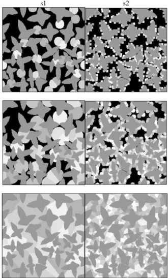
Results related to the second stage of the process are summarized in Figures 4–5. Corresponding distributions of the two types of structure, for two macroscopic elements, for two eutectic modes, and for different time steps (including the final structure) are shown in Figures 4 and 5. We can observe that different eutectic transformation modes result in different average radius of eutectic grains, smaller eutectic grains are observed in unmodified alloys.
a)
b)
Fig. 3. Cooling curves for two cooling rates (a - �̇ = �⁄ ,
b - �̇ = �⁄ ), for two eutectic transformation modes: (s1
and s2). S1 corresponds to nucleation of independent (from dendritic grains) eutectic grains, s2 corresponds to nucleation of eutectic grains in adjacency of dendritic grains. In Figure the end
of the solidification process is marked by dots
Analysis of Cooling Curves for Al-7% Si Alloys
alloys. Moreover, recalescence is observed at relatively higher temperatures. These two tendencies follow from the fact that more grains nucleate and the aggregated surface of growing grains is greater. Consequently, more latent heat is generated at the beginning of the second stage of the process, and the temperature increases earlier. In addition, in the case of unmodified alloys, the impingement factor has minor effect on generation of latent heat. The aggregate surface of growing eutectic grains is affected by impingement at the beginning and at the end of the transformation, and during remaining parts of the process interaction with other grains is being stabilized. As a consequence a narrow range of temperatures for eutectic transformation is obtained.
s1 s2
Fig. 4. Grain structure in macroscopic elements for cooling rate
̇ = ⁄ , for different time steps t=100 s, 120 s, and the
final structure. S1 corresponds to nucleation of independent (from dendritic grains) eutectic grains, s2 corresponds to nucleation of
eutectic grains in adjacency of dendritic grains
On the contrary, in modified alloys, fewer grains grow and even local changes in their size can affect significantly the amount of latent heat generated. Such local changes can be a result of the impingement between grains. At any point of time growing eutectic grains may encounter dendritic grains that act as a barrier. At the same time, when the growing eutectic grains overgrow the dendritic grains, they regain ability to grow freely. When the
amount of latent heat is decreased, the temperature decreases as well and the solidifying material transforms with higher undercooling. This blocking factor is more dominant at the end of the eutectic transformation. Hence, the last portions of solidifying material are solidifying with higher undercooling. For modified alloys the solidification process ends at lower temperature compared to the unmodified alloys.
s1 s2
Fig. 5. Grain structure in macroscopic elements for cooling rate
̇ = ⁄ , for different time steps t=13 s, 17 s, and the
final structure. S1 corresponds to nucleation of independent (from dendritic grains) eutectic grains, s2 corresponds to nucleation of
eutectic grains in adjacency of dendritic grains
Validation of Obtained Numerical Cooling Curves for Modified and Unmodified Alloys
In order to validate obtained numerical cooling curves we compared them with corresponding results obtained with analytical model. Because the first stage of process is identical for two modes of eutectic transformation, we limit our comparison only to the second stage of the process. For this purpose, we chose an analytical model that is the most often utilized among macro-micro models [12, 15-18]. Here we briefly describe this model, limiting presentation only to its most important details.
In macro-micro models, spherical growth within representativeelementaryvolume is assumed and two values are introduced: the extended volume, , and transformed volume, . The extended volume is the total transformed volume of crystals when impingement between them is neglected. In turn, transformed volume of crystal is the total transformed volume of crystals when impingement is taken into account. If we define the transformed phase volume fraction as f = ⁄ and extended phase volume fraction as f = ⁄ , we can relate them by the well known JMAK equation:
f = 1 f . (4)
The above equation is one way to introduce the impingement into growth model. Another way would be to decrease the growth rate of eutectic growth by multiplying the growth velocity (Equation 3 from Part I) by factor 1 f . The later procedure is applied in models that describe solidification of alloys, with dominant eutectic structure. When grains nucleate at the boundary of other grains, the correcting factor must be changed as in [18]. Different forms of correcting factor should be also utilized when grains can move during growth process, as it was shown in [19]. For hypoeutecitc alloys preexisting dendritic structure may also delay the growth process of eutectic grains, and correcting factor is also required, as stated in [12,15]. Various types of this factor have been used for hypoeutectic alloys [12, 15, 17, 18]. For comparison purposes we have chosen the following factors: 1 f , 1
f , 1 f .
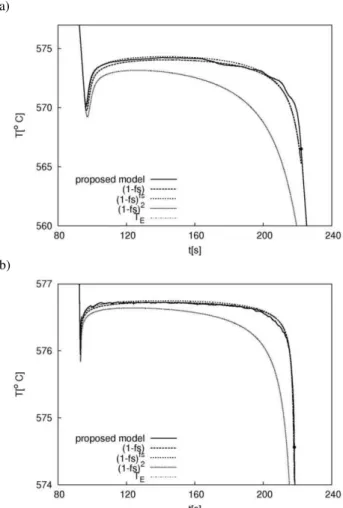
We designed a set of experiments for both models. Obtained results are presented in Figure 6. As can be seen only one curve, corresponding to the factor 1 f , diverges from the others, including cooling curves obtained by our model. Curves corresponding to other two factors are convergent with each other and with curve obtained by means of the proposed model. We noted that for both eutectic transformation modes the same correcting factor in analytical model can be used to describe eutectic structure evolution in case of hypoeutectic alloy. This implies that in order to take into account various eutectic transformation modes, there is no need to differentiate between various correction factors.
The only difference occurs close to the end of eutectic transformation process for modified alloys, i.e. in Figures 3b and 6a. A small perturbation visible in the curve generated by our model is a result of impingement of growing eutectic grains upon dendritic grains. This perturbation depends on position and the number of both dendritic and eutectic grains, and hence it is hard to capture it by the analytical models. When many eutectic grains have nucleated this effect is minimized and the perturbation is not observed, like in the case of unmodified alloys (Figure 6b).
a)
b)
Fig. 6. Results of comparison between proposed model and analytical models 1 f , 1 f , 1 f for cooling rate
-2degs, for both modified alloys (a) and unmodified alloys (b)
This comparison shows also that both models can be successfully utilized to model two stage solidification. However, analytical models are unable to determine the topological evolution of polistructure. Thus, when such information is crucial, analytical models are of little application.
4. Conclusion
In the paper verification of two-stage solidification model, described in Part I of this paper, has been presented. Computer simulations have been executed for an Al-7%Si alloy and for two macrosopic elements, with two cooling rates, i.e. ⁄ and
⁄ . Simulations show that obtained curves for modified
model with analytical models in terms of cooling curves. Unlike the analytical models our approach provides information about gradual topological transition of microstructure, which is crucial in modeling phenomena that relay on local topological changes in microstructure (such as defects formation in castings). To the best of our knowledge presented approach is the only one that allows to capture simultaneously microstructure, temperature and size of the structure constituents in two-stage solidification, and that include different modes of the eutectic transformation.
References
[1] S. McDonald, K. Nogita, A. Dahle, J. Taylor, D. StJohn. (2000). Eutectic solidification and porosity formation in Al– Si alloys role of strontium. AFS Transactions.115, 463-470 [2] A. Dahle, K. Nogita, J. Zindel, S. McDonald, L. Hogan.
(2001). Eutectic nucleation and growth in hypoeutectic Al–Si alloys at different strontium levels. Metallurgical Materials
Transactions.32A, 949–960
[3] C. Dinnis, A. Dahle, J. Taylor, (2005). Three-dimensional analysis of eutectic grains in hypoeutectic Al–Si alloys.
Materials Science and Engineering A. 392A, 440–448
[4] S. McDonald, K. Nogita, Dahle, J. Taylor, D. StJohn. (2000). Eutectic solidification and porosity formation in Al–Si alloys: role of strontium. AFS Transactions. 108, 463-470 [5] C. Dinnis, A. Dahle, J. Taylor. (2005). Three-dimensional
analysis of eutectic grains in hypoeutectic Al–Si alloys.
Mater. Science and Engng A.392 A, 440–448
[6] S. McDonald, K. Nogita, A. Dahle. (2004). Eutectic nucleation in Al-Si alloys. Acta Mater.52, 4273–4280. [7] K. Nogita, S. McDonald, A. Dahle. (2004). Eutectic
solidification and its role in casting porosity formation. JOM.
56, 52–58
[8] S. McDonald, A. Dahle, J. Taylor, D. StJohn. (2004). Eutectic grains in unmodified and strontium-modified hypoeutectic aluminium-silicin alloys. Metall. Mater. Trans. A. 35A, 1829–1837
[9] C.-A. Gandin, M. Rappaz. (1994). A coupled finite element cellular automaton model for the prediction of dendritic grain
structures in solidification processes. Acta Metallurgica et
Materialia. 42, 2233–2246
[10]J. Gawad, P.Maciol, M. Pietrzyk. (2005). Multiscale modeling of microstructure and macroscopic properties in thixoforming process using cellular automation technique.
Archives of Metallurgy and Materials. 50, 549-562
[11]L. Madej, J. Talamantes-Silva, I.C. Howard, M. Pietrzyk. (2005). Modeling of the initiation of the shear band usinf the coupled CAFE model. Archives of Metallurgy and Materials.
50, 563-573
[12]C. Gonzalez-Rivera, B. Campillo, M. Castro, M. Herrera, J. Juarez-Islas. (2000). On the local microstructural characteristics observed in sand cast Al–Si alloys. Materials
Science and Engineering A. 279, 149–159
[13]M. Rappaz, P. Thevoz. (1987). Solute diffusion model for equiaxed dendritic growth. Acta Metallurgica. 34, 1487– 1497
[14]Q. Du, D. Eskin, A. Jacot, L. Katgerman. (2007). Two-dimensional modelling and experimental study on microsegregation during solidification of an Al–Cu binary alloy. Acta Mater. 55, 1523–1532
[15]D. D. Goettsch, J. Dantzig. (1994). Modeling microstructure development in gray cast irons. Metall. Mater. Trans. A.
25A, 1063–1079
[16]D. Celentano, M. Cruchaga. (1999). A thermally coupled flow formation with microstructural evolution for hypoeutectic cast-iron solidification. Metall. Mater. Trans. B. 30B, 731–744
[17]D. Maijer, S. Cockcroft, W. Patt. (1999). Mathematical modeling of microstructural development in hypoeutectic cast iron. Metall. and Mater. Trans. A. 30, 2147–2158 [18]S. Chang, D. Shangguan, D. Stefanescu. (1992). Modeling of
the solid/ liquid and eutectoid phase transitions in the spheroidal graphite cast iron, Metall. Mater. Trans. A. 23A,
1333-1346