Influence of parameters variation on a shielded line
submitted at a punctual injection current at any
position along its length
Kaoutar Senhaji Rhazi1
, Mohamed Najmouddine2 1
ENSEM’s Lab of electrical engineering Km 8, road El Jadida B.P 8118 Oasis Casablanca, Morocco,
2
ENSEM’s Lab of electrical engineering Km 8, road El Jadida B.P 8118 Oasis Casablanca, Morocco,
Abstract
Firstly, I note that this draft article is an article continuation already published in your journal in September 2012; n°IJCSI-2012-9-5-3873. This is the reason why you will find repeated diagrams and explanations in order to introduce new work. In reference to articles previously published, one in your journal and two others articles already published in the Annals of telecommunications journal, which we will quote a summary in the following paragraph again, this paper provides a study of the factors influence on a shielded line submitted at a punctual injection current at any position along its length. In the previous article, published in your journal, we have studied the influence of four of them. This study helps to study
the influence of four other parameters.
Using simulated line for geometric dimensions respecting the line theory assumptions, we try to analyze the sensitivity to changes in various parameters.
Keywords: transmission line, electromagnetic disturbance, modeling, punctual injection current,
parametric sensitivity.
Summary
1. Introduction
1.1.
Summary of previously published articles1.2.
Geometrical characteristics and configurations of excitation of the line of transmission model1.3.
Case of a row with a cable whose shielding is likened to a helical ribbon above a plane of ground2. Conclusion
3.
Bibliography 4. Biography1. Introduction
The design of low-level circuits involved in control systems in the large industrial sites has been for many years, discussions subject of the choice of cable types to use and especially the mode of grounding their shields. Indeed, the cables that connect low electronic components are particularly sensitive to various sources of electromagnetic
interference. For more clarification on the this
article’s finality, we can refer to articles previously published, by the same team in your journal entitled “study of parametric sensitivity of the general model of transmission line” in September 2012; number IJCSI-2012-9-5-3873; and in the annals of telecommunications, respectively entitled "Approached expressions at the low and high frequencies of the induced tensions of common-mode at the end of a shielded line submitted to a punctual injection of current" in March 2005 (n ° 3/4) and "Determination of the disturbance at the ends of a shielded line subject to a punctual excitation current", in November 2002 (n°11/12). Transfer impedance is the quantity which allows the quantitative assessment of the quality of shielding a cable. We also know that the modeling project of a shielded line subject to current disruption in any position of its length, involves several factors. Some of these factors have a major influence on the assessment of parasitic tensions, others are probably less important, so it is necessary to determine the effect on the result for each of them, to conduct a study on parametric sensitivity.
The digital model validated by the previous experiences will allow us to make this study and assess the influence obtained by the variation of each parameter characterizing a line with two strictly coaxial conductors above a perfectly conducting plane of ground. We are still interested in the case of a screen characterized by a poor electromagnetic protection that may form for example a metallic ribbon helically wrapped. This time, we will explore additional parameters in addition to those discussed in the previous article
1.1.
Summary of previously published articlesTwo articles mentioned above were published in the “telecommunications’ annals” journal. For the article published in November 2002 (n°11/12), we were able to determine the perturbation induced at the ends of each coaxial line on a wide band of frequencies. The source of disruption is a punctual direct current injection on the shielding of the cable in any position. For that, we applied the theory of state variables, on the base of approximation quasi-TEM, to model the coaxial line over a plan of ground with a finite conductivity. This allowed us to provide expressions of tensions and currents at the two ends of the line under their analytic forms for any load conditions. Then, an experimental verification was made to validate the developed code of calculation. Concerning the article published in March 2005 (n°3/4), we were able to determine approached expressions at the low and high frequencies of the induced tensions of common-mode at the end of a shielded line submitted to a punctual current injection, for the case of a helical ribbon. This article also discusses the correction function, the relationship between the exact value and the approximated one of the disturbance and the limit of validity to the high frequencies approached expressions established at low frequencies. For theArticle published in your journal in September 2012 (n°IJCSI-2012-9-5-3873°, the transfer impedance is the size that allows quantitative assessment of the quality of a shielded cable. The numerical model validated by various previous studies to perform this study and evaluate the influence obtained by the variation of each parameter characterizing a line with two coaxial conductors strictly above a perfectly conducting ground plane. In this paper (published in September 2012), we studied the influence on the module Ztg(transfer impedance overall), for four parameters:
-The length l 2 of the line portion, located between
the point of injection and the left end of the line
-The total coaxial line length Lof the coaxial line
-The Transfer resistance RT of outside driver of the
coaxial line
-The Transfer inductor LT from outside driver of the
coaxial line
In this paper, we will study the influence of other parameters, namely:
-The inner radius “a” of the shield of the coaxial line
-The height hR of the coaxial line
-Resistance ZR the inner conductor of the coaxial line
-Relative permittivity εr1 of the dielectric within the
coaxial line
-Relative permittivity εr3 of the dielectric outside
the coaxial line
1.2. Geometrical characteristics and configurations of excitation of the model of line of transmission
Always in reference to the articles previously published, the type of shielded transmission line that we consider as the basic circuit includes two coaxial conductors (length L) above a perfectly
conducting plane of ground. This condition on the conductivity of the plane of ground is usually required to not further complicate propagation conditions that can occur at high frequencies. The transverse dimensions and the position of the disturbance are represented on figure 1.
Always remember that:
εr1 and μr1 are respectively the permittivity and
permeability of the inner dielectric environment, and εr3 and μr3 are the corresponding values of the
outer dielectric. We consider that μr1 and μr3 are
those of the vacuum and the dielectric environment outside the cable is the open air. VRl2 is the induced
voltage of common mode on the internal conductor to the left end of the line, and I is the total disruptive current. L is the total length of the line,
hR is the height at which the line is from the ground;
a and b are respectively the inside and outside rays of the external conductor and rR is the radius of the
inner conductor. l1 and l2 are the portions of the line
between which the disruptive power is.
The values of the parameters presented in the table below (already given in the previous article, March 2005) are chosen arbitrarily but comply with the basic theory of transmission lines assumptions.
L
l
2 l1
VRl2
I
Reference plane
rR
εr1 μr1
εr3 μr3
b
h
R
a
In this study, they represent the reference’s values that correspond to a reference’s curve related to a definite load configuration.
To simplify this study, we made the assumption that the resistance of the conductor is a constant. We are interested in the case of a shielding that strongly promotes the penetration of the electromagnetic field (helical ribbon).
As in the previously published article (March 2005), simulations concern the variations according to the frequency of the Ztg module, that is to say the
ratio of the induced voltage of common mode on the inner conductor in the left end of the line to total disruptive current. The left end of the line is supposed to be the end where the disturbance-sensitive instrumentation is.
Three configurations of excitation characterized by conditions at the ends often encountered in practice, will allow us to simulate a transmission line shielded connecting an equipment to another. Loads at the ends of the internal conductor simulate input and output impedance of the equipment. Additional configuration for which shielding is open at both line’s ends, is used for comparison and may represent the case of involuntary defect in connections between ground and shielding.
Excitation configurations are represented in figure 2 below.
To highlight the effect produced by each parameter on the result of Ztg, we propose to varysuccessively
each parameter while keeping, the others equal to their reference’s values. The results reproduced on all of the plates are calculated between 1 kHz and 10 MHz by setting two additional values around the reference value to each parameter. For more convenience in the analysis of the results, we assembled the effect of a parameter for the four configurations on the same plate. In addition, for a good precision, we increased the number of points calculated by decade of frequency to 150 points, which is not without consequences on the calculation time of each simulation. Furthermore, we retained the four-letter code to designate each configuration. These four letters represent the successive order of load impedances at both line’s ends starting with the shielding and from right to left. The letter 'O' corresponds to an open circuit, ‘C’ to a short circuit and 'Z' to the characteristic impedance of the line formed by two coaxial conductors.
1.3 Case of a row with a cable whose shielding is likened to a helical ribbon above a plane of ground
Always in reference to previously published articles and in order to quantitatively represent the phenomenon of diffusion through the screen of a cable, we consider a poor quality screen made by a helical ribbon and whose transfer impedance ZT is
characterized by the following approximated expression:
Reference values used for lineic parametric calculation
Values kept constant Values for which we
study the sensitivity
L =100 m
l
2 = 5 m
a = 4 mm b-a = e= 0.2 mm hR =50 mm ZR = 0.01 Ω/m εr1 = 2 εr3 = 1
rR = 0.7 mm μr1 = 1 μr3 = 1
Table 1: reference values
Fig. 2 Configurations of excitation considered in the simulations
VV
l 1 l
2
L
I
VV
l 1 l
2
L
I
VV
l 1 l
2
L
I
VV
l 1 l
2
L
I Z
Z
Plane of ground ‘O.O.O.O’configuration
Plane of ground ‘O.C.O.O’configuration
Plane of ground ‘C.C.O.O’configuration
ZT =RT+ jωLT (1)
Like the reference value, the resistance value in continuous current RT is chosen equal to 10mΩ/m
and the inductor LT is taken equal to 16nH/m. Such
values are arbitrary and should not be interpreted as obtained from the geometric dimensions from the line; in other words, they are independent from the diameter and the thickness of the screen.
1.3.1. Parametric sensitivity
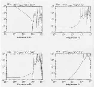
Figures 3 to 7 give below, provide the calculated values of Ztg module by successively varying each
parameter for the four load configurations.
Fig. 3 Influence, on the Ztg modulus, of the radius a
of the coaxial line shield
(_____ :a=4 mm),(--- : a= 10 mm) et (….. a= 2 mm)
Fig. 4 Influence, on the Ztg modulus of the coaxial line height hR
(_____ : hR=5cm), (--- :hR = 50 cm) et (……
Fig. 5 Influence, on the Ztg modulus, of ZR
resistance of the coaxial line inner conductor
(_____ : ZR=10mΩ/m), (--- :ZR=100mΩ/m) et
(….. : ZR= 1mΩ/m)
Fig. 6 Influence, on the Ztg modulus, of the
dielectric relative permittivity εr1 inside the
coaxial line
1.2.2. Discussion
The results presented in Figure 3 (variation of the space between the inner conductor and the shield) show that in this case where the transfer impedance is defined as an independent function of this space, this parameter only affects the configuration in which the shield is open circuited at both ends. It is obvious that for this configuration where the coupling is essentially capacitive type, the Ztg module is determined by the line admittance formed by the shield and the ground plane and therefore increases when the admittance decreases. The same is true for the line height variation (Fig. 4), but especially when at least one end of the shield is grounded the height parameter does not
affect the result.
On the other hand, respecting the realistic values for the resistance of the inner conductor, Figure 5 shows that this resistance has no significant effect on the calculation results because of its negligible value compared to the terminal impedances of common mode considered in this study. However, it gives rise to an attenuation constant that can absorb some resonance peaks at higher frequencies must take place where the skin effect which obviously neglected in this study.
The relative permittivity influence of the inside dielectric medium εr1 cable on the simulation results obtained for the four configurations shown clearly in Figure 6.
We note that on low frequencies, the interference voltages amplitudes are independent of the value assigned to this parameter except for the configuration "CCZZ" where impedance characteristic of the line Z = ZCR itself is theoretically defined as a function of the constant, that is to say, the load impedances are different for different values of εr1.
Indeed, one of the features of particular interest of the transmission lines at high frequencies is the characteristic impedance. A coaxial line for using an insulating material which the relative permittivity is εr1 and the permeability is that of the vacuum, this expression reduces to the expression:
ε
1
0
r
R
R
R
C R
L
v
C
L
Z
=
=
(2)
Where LR, CR and v0 are respectively the inductance per unit length, capacitance per unit length and the
speed of light.
The same remarks apply to the curves of Figure 7 for the medium dielectric permittivity that surrounds the line.
We also note that εr3 does not affect the low frequencies in the configuration "CCZZ" since in this case εr1 being constant, the ZCR is being too.
These results highlight the relative permittivity effect of dielectric media on the evolution versus frequency of Ztg calculated modules.
Thus, the propagation modes can be considered as quasi-TEM and dielectric media can be assimilated in the open air at low frequencies. By cons, for high frequencies, from solving coupling problems, signal waveforms are very attached to velocities and therefore the values assigned to the dielectric media
relative permittivity.
These results confirm the interest of using structures better electromagnetic immunity shielded to protect lines against low external disturbances.
These results show once again that when the cable shield is in the air at both ends, its ability to reduce disturbance is almost zero and we find almost the same common mode voltage in the total absence of shielding.
2. Conclusion
Fig. 7 Influence, on the Ztg modulus, of the
dielectric relative permittivity εr3 outside the coaxial line
The numerical model validity allowed for a study of parametric sensitivity. In this study, we presented and discussed the numerical simulations obtained results. It was made clear that the weak coupling assumption is still effective. It has also emphasized the need to properly ground the two ends of the cable shielding, in particular the right equipment sensitive to disturbance.
It is also clear from this study that, apart from cases where the shield is in the air at both ends and the position of the resonance peaks, only the transfer impedance, line length and frequency decisive.
Was determined separately influence on the level of interference voltages, some parameters involved in the modeling of a shielded line above a perfectly conducting ground plane.
Among the main parameters, the transfer impedance is of particular interest since we see her appear essential that clearly explains the function screen shielded transmission lines.
3. Bibliography
[1] K. Senhaji Rhazi , M.Najmouddine, “study of parametric sensitivity of general model of transmission line”. IJCSI – September 2012 Issue (Volume 9, Issue 5):IJCSI-2012-9-5-3873
[2] K. Senhaji Rhazi , M.Najmouddine, J. Hoeffelmann, , A. Lamine , "Approximate expressions at low and high frequencies of induced voltages of common mode at the ends of an armored submissive line at a punctual injection of current". Ann. Telecommun.60, n ° 3-4, pp454-471, March April 2005
[3] M.Najmouddine, K. Senhaji Rhazi J. Hoeffelmann, “Determination of disturbances induced at the ends of a line reinforced subjected to point excitation current ", Ann. Telecommun. , 57, n ° 11-12, pp.1091 - 1123, November-December 2002"
[4] SHELKUNOFFE.F (SA) "The electromagnetic theory of coaxial transmission lines and cylindrical shields," Bell System Tech. Day., Pp. 533-579, October 1934.
[5] BLECH (P.), DIJAMATOVIC (Y) and Ianoz (Mr.) "Measurement of the impedance transfer in pulsed mode," Tech. MES, Bulletin ASE / UCS 78, no.. 9, pp. 488-492, May 1987.
4. Biography
I am Mrs. Senhaji Rhazi Kaoutar, an assistant professor at the superior school of technology (EST) in Casablanca, Morocco. I wish to inform you that I'm preparing my habilitation (in the field of electromagnetic compatibility). I completed the national thesis in July 2006. I got the research