DSP Systems
vs
ANN Ensembles
for Motion Detection and Filtering
Kevin Emanuel Moorgas and Poobalan Govender
Abstract – This paper presents a comparative study between
digital signal processing (DSP) systems and artificial neural networks (ANN’s) for object motion detection and object extraction. The ANN’s are arranged as an ensemble to perform the motion detection and image subtraction function. The ANN system displays a superior performance over the DSP in terms of system complexity and image quality.
Index terms - artificial neural networks, digital signal processing, ensembles, filtering
I. INTRODUCTION
Fundamental to DSP systems is the study of discrete – time systems that process digital signals to extract or modify information. When compared to analogue systems: DSP systems have fewer components, are not prone to the effects of component ageing, are much more flexible, and have a higher noise immunity [7]. Computational based systems, or so-called intelligent systems, such as fuzzy logic, genetic algorithms, evolutionary programming and ANN’s offer better performances for most applications when compared to conventional systems [10].
Popular image processing systems utilize digital signal processing (DSP) techniques [1]. Aliasing and filtering are considered to be problematic processes in DSP based image processing systems [4], [7], [9]. To overcome some of these shortcomings we propose an intelligent ANN system that is robust and immune to noise. Intelligent systems are widely applied in pattern recognition, security surveillance and biomedical imaging [5], [8]. Furthermore changes in input data, such as illumination and varying noise levels, are handled more robustly by ANN systems [10], [12]. This paper is arranged as follows: section 2 discusses DSP for motion detection and image
WCECS Proceedings 2008
Paper first received 22 July 2008 and in revised form xx 2008. The work was supported by the National Research Foundation of South Africa. NRF under Grant Number 62387;
Grant holder- P.Govender.
First Author: Department of Electronic Engineering, Durban University of Technology, Durban, South Africa;
Email: [email protected]
Second Author: Department of Electronic Engineering, Durban University of Technology,Durban, South Africa;
Email: [email protected]
extraction; section 3 describes the design and implementation of an ANN system for motion detection and image extraction; section 4 compares the performance of DSP vs ANN’s for motion detection; section 5 concludes the study.
II. DSP IN MOTION DETECTION
The 2D Fourier Transform (FT) (1) and Discrete Fourier Transform (DFT) (2) is widely used for image processing operations [2], [4].
1 ,..., 2 , 1 , 0 , ) ( 2 exp ] , [ 1 ) , ( ) 1 ( )] ( 2 exp[ ] , [ ) , ( 1 0 1 0 − = ⎥⎦ ⎤ ⎢⎣ ⎡− + = + − =
∑ ∑
∫ ∫
− = − = ∞ ∞ − N v u N vy ux j y x f N v u F dy dx vy ux j y x f v u F N x N y π π α (2) With regards to (1) and (2): u and v denotes the frequency variables; f [x,y] is a square M x N digital image matrix. For this study (2) represents frequency components of a grey scaled image frame square matrix fα[x,y], with α representing the frame number.The high frequency components of the DFT represent sharp variations, or edges, in pixel gray levels that occur along the borders or within the texture of an image. Along these edges the pixel intensity changes rapidly across a boundary and at high frequencies of the DFT [2], [7], [16]. The pixel intensity of an object and its edges is what identifies a region of interest (ROI) from its background [11]. For the first part of our study using DSP for motion detection and isolation, the edges of an object will be detected and extracted. The steps followed will include: image subtraction, image enhancement and filtering.
A. Image Subtraction
A.1: Background Subtraction:
(3) removed the background leaving only the ROI where the change in pixel intensity indicates motion.
ƒα[x,y] – B = G (3)
where B denotes the static background, Gis the cluster of pixels in the ROI and α indicates the number of captured frames. This motion can be shown as the pixel intensity of G in any captured frame ƒα [x,y] with G > 0; G = 0 of the same frame indicated a no motion region and an irrelevant area of background infα[x,y].
A.2: Temporal Differencing:
Temporal differencing is applied to each successive frame following background subtraction. The extracted ROI becomes the new image frame (4):
ƒr [x,y] = ƒα [x,y] – B (4)
With regards to (4): ƒr [x,y] is the resulting new frame following background subtraction, where r denotes the frame number and α indicates the number of captured frames. (5) and (6) are used for temporal differencing. With regards to (5): H1, H2, …Hnth represents the
image matrix ƒr [x,y] and C1, C2,…Cnth is the resulting
matrices of the sequence S1. Temporal differencing was then applied to each successive matrix frame of (6)
S1 = [H1 – B1], [H2 – B2] ,….., [Hnth – Bnth] =
C1, C2 ,….., Cnth (5)
Cd1=|C1-C2|, Cd2=|C2-C3|,…,Cdnth=|Cn-1-Cn| (6)
With regards to (6), each C-matrix is subtracted from
its preceding matrix. The difference between the two corresponding image matrix values were converted into an absolute value and stored in a difference matrix Cd to eliminate negative values. This process is continued for all images in the frame matrix. Motion mask U (7) is obtained from S1 following background
subtraction.
⎭ ⎬ ⎫ ⎩
⎨
⎧ >
=
_ 0
0 1
motion no
C
U d (7)
U is applied to each successive difference matrix Cd and results in image matrix sequence S2 (8).
S2 = Cd1, Cd2, …,Cdnth (8)
B. Image Enhancement and Filtering
(8) is enhanced by increasing the contrast of the images to clearly define ROI. Image enhancement also enhances
noise as indicated in Fig. 1(c), Fig. 2(c) and Fig. 3(c). Median filters based on the 2D convolution algorithm (9), (10) are used in image processing to avoid the side effect damage to pixels within the ROI [13], [17].
] , [ ]
,
[x y f x y
f
ffilter = Z ⊗ win (9)
∑ ∑
−= −
=
− −
= 1
0 1
0
] , [ ] , [
1 M
m N
n
win z
filter f m n f x m y n
MN
f
for x = 0,1,2,……, M - 1 and y = 0,1,2,….., N - 1 (10)
With regards to (9) and (10): ffilter represents the resulting filtered image, fwin[x,y] is the filtering window
having x-rows and y-columns and fz [x,y] denotes the 2D
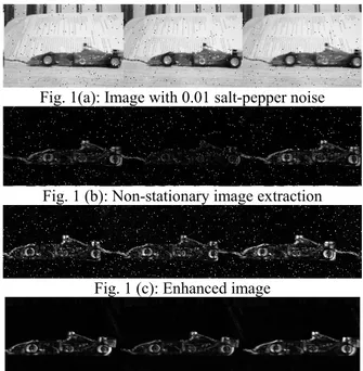
frame sequence following the introduction of noise. In our study the median filter minimizes noise whilst preserving edges and high any frequency components defined by (2). (11) shows the introduction of noise and the resulting image sequence, where ψ represents different levels of induced salt and pepper noise; Z denotes the image following the introduction of noise shown in Fig. 1(a), Fig. 2(a) and Fig. 3(a).
(Cd1, Cd2, …,Cdnth ) ψ = Z1, Z2, ….,Znth (11)
Median filtering is applied to frames in Fig. 1(c), Fig. 2(c), and Fig. 3(c) and the resulting filtered image sequences are shown in Fig. 1(d), Fig. 2(d), and Fig. 3(d).
Fig. 1(a): Image with 0.01 salt-pepper noise
Fig. 1 (b): Non-stationary image extraction
Fig. 1 (c): Enhanced image
Fig. 1 (d): Image following median filtering
Fig. 2 (a): Image with 0.05 salt-pepper noise
Fig 2 (b): Non-stationary image extraction
Fig 2 (c): Non-stationary image enhancement
Fig 2 (d): Resultant image following median filtering
Fig. 2: DSP moving object detection and filtering (0.05 salt-pepper induced noise)
Fig 3 (a): Image with 0.09 salt- pepper noise
Fig. 3 (b): Non-stationary image extraction
Fig. 3 (c): Non-stationary image enhancement
Fig. 3(d): Resultant image following median filtering
Fig. 3: DSP moving object detection and filtering (0.05 salt-pepper induced noise)
III. ANN MOTION DETECTION SYSTEM
ANN’s consist of individual processing elements, termed neurons, that are modeled along the lines of the biological neuron. Each artificial neuron consists of an input, weight, summation, activation function and an output. For this study the ANN system in Fig. 4 uses multilayer feedforward (MLFF) backpropagation networks and a log-sigmoid nonlinear activation function to detect motion and remove any stationary background[15]. The MLFF architecture is designed with two hidden layers and an output layer, having 100, 200 and 255 neurons respectively. The output layer maps corresponding pixel elements from an input image matrix to the output image matrix. The ANN’s are arranged to operate as an ensemble to reduce computational burden and promote faster processing times when handling the large quantities of image data [17], [18]. In this study image sequences are split into single frames that are applied to the ANN. The ANN’s detect any motion and display the new position of the object.
Fig.4: ANN motion detection system
A.Testing
S3 = (H'1, H'2,……H'nth) (15)
With regards to (15), H' represents the respective image frame matrix applied to its corresponding network in the ensemble. The first layer of ANN’s behaves as a motion detecting ensemble to indicate the new position of the object. The output is represented by S4 (16)
S4 = (C'1, C'2,……..,C'nth ) (16)
The second layer of ANN’s performs the image subtraction to remove any stationary background. The out of the system indicates the non-stationary object sequence given in (17) Fig. 7(c)
S5 = (C'd1,C'd2, ……,C'dnth) (17)
A. ANN Noise Filtering and Image Enhancement
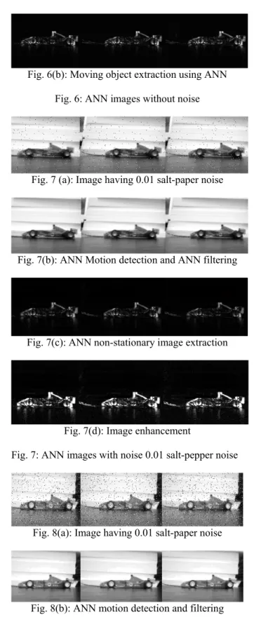
ANN’s are robust processing elements and have the ability to remove unwanted noise signals from the images under consideration. The noise immunity of the ANN system in Fig. 4 is tested by adding different levels of ‘salt and pepper noise’ to the image sequence before it is applied to the NN (Fig. 7(a), Fig. 8(a) and Fig. 9(a)). The output of Fig. 4 is given in Fig. 7(b), Fig. 8 (b) and Fig. 9 (b). Image subtraction is performed within the NN system and removes any stationary background from the sequence - Fig. 7(c), Fig. 8(c) and Fig. 9(c). To ensure the validity of the comparison between the ANN and DSP systems, the image sequence is enhanced and filtered under the same conditions as the DSP in order to standardize the end processing for comparison (Fig. 7(d), Fig. 8(d) and Fig. 9(d)).
Fig. 5: Training Image Sequences for ANN
Fig. 6(a): Motion detection using ANN
Fig. 6(b): Moving object extraction using ANN
Fig. 6: ANN images without noise
Fig. 7 (a): Image having 0.01 salt-paper noise
Fig. 7(b): ANN Motion detection and ANN filtering
Fig. 7(c): ANN non-stationary image extraction
Fig. 7(d): Image enhancement
Fig. 7: ANN images with noise 0.01 salt-pepper noise
Fig. 8(a): Image having 0.01 salt-paper noise
Fig.8(c): Non-stationary image extraction using ANN
Fig. 8(d): Image enhancement
Fig. 8: ANN images with 0.05 salt-pepper noise
Fig 9(a): Image having 0.09 salt-paper noise
Fig 9(b): ANN motion detection and ANN filtering
Fig 9(c): ANN moving object extraction
Fig 9(d): Image enhancement
Fig. 9: ANN images with 0.09 salt and pepper noise
IV. COMPARING THE PERFORMANCE OF DSP VERSUS ANN’S A. Noise
The Peak Signal-to-Noise Ratio (PSNR) (19) is used to measure the image quality of the image produced by the DSP and ANN systems.
MSE g g PSNR
2 min max 10
] [
log
10 −
= (19)
With regards to (19), gmax and gmin indicate the maximum and minimum pixel values for an image frame; MSE is the mean squared error for two m x n monochrome images. Fig. 10(a) and Fig. 10(b) gives the response of the DSP versus the ANN system for different noise levels. With regards to Fig. 10(a)-Fig. 10(c):
Frame sequence 1-Noise is induced: ANN and DSP system with similar PSNR at beginning of test (Fig.1(a)-Fig.3(a), Fig. 7(a)-Fig. 9(a))
Frame sequence 2-Motion is detected: The ANN system inhibits any negative effects of noise on the image quality (Fig.1(b), Fig.3(b), Fig.7(b), Fig.9(b)). Frame sequence 3-DSP with median filter: The performance of the ANN as a filter yields a higher quality image over the DSP (Fig.1(d), Fig.3(d), Fig.7(b), Fig.9(b)).
Simulation With Salt & Pepper Noise(0.01)
0 5 10 15 20 25
1 2 3
Im age Fram e Sequences
PS
N
R
(d
B
)
ANN DSP
Fig. 10(a): Responses using 0.01 salt-pepper noise
Sim ulation With Salt & Pepper Noise (0.05)
0 5 10 15 20 25
1 2 3
Im age Fram e Sequences
P
S
NR(
d
B
)
ANN DSP
Fig. 10(b): Responses using 0.05 salt-pepper noise
Simulation With Salt & Pepper Noise(0.09)
0 5 10 15 20 25
1 2 3
Im age Fram e Sequences
P
S
NR(
d
B
)
ANN DSP
Fig. 10(c): Responses using 0.09 salt-pepper noise
B. Average Processing Time
Table 1 shows the average processing time of each system. The DSP system shows off a far more superior processing time than the ANN system even when the training time is not considered. Although the DSP is faster, its algorithms are mathematically intensive and complex [14]. DSP systems become expensive at high bandwidths and the cost of high – speed analogue to digital and digital to analogue converters at speeds higher than 100 MHz makes them impractical for many applications. High power consumption and size of DSP systems can make them unsuitable for simple very low–power or small size applications. If computation time is not critical then the proposed ANN system is much more viable.
V. CONCLUSION
This paper proposed an ANN system for motion detection and object extraction by using an ANN ensemble trained to behave as a motion detector. The ANN system outperforms the DSP in all aspects save computation time and the tests prove that ANN’s have an inherent ability to minimize any negative effects of system noise without the complexity of DSP.
TABLE 1: Average System processing time
REFERENCES
[1] S. M. Desa and Q. A. Salih, “Image Subtraction for Real Time Object Extraction,” IEEE , Proc.-Int’l. Conf. on Computer Graphics, Imaging and Visualization, pp xx-xx, 2004
[2] R. C. Gonzalez, R. E. Woods and S. L. Eddins, “Digital Image Processing Using Matlab”, Prentice Hall, 2004
[3] H. S. Yazdi, M.L. and M.Fathy, “Car Tracking by Quantised Input LMS, QX-LMS Alorithm in Traffic Scences,” Proc.-IEE Conf.,-Vis. Image Signal Process, Vol.153(1), pp 37-44, February 2006
[4] S. K. Mitra, “Digital Signal Processing, “A Computer –Based Approach”. McGraw Hill, 1998.
[5] L. O. Murta Jr, E.E.S. Ruiz, A. Pazin-Filho, A. Scmidt, O.C. Almeida-Filho, M.V. Simoes, J.A. Marin-Neto and B.C. Maciel, “Automated Grading of Left Ventricular Segmental Wall Motion by an Artificial Neural Network Using Color Kinesis Images,” Trans. - Brazilian J’nl of Medical and Biological Research, 39(1), ISSN 0100-879X, pp xx-xx, 2006
[6] M.T. Hagan, H. B. Demuth and M.H. Beale, “Neural Network Design, ” Boston, MA: PWS Publishing, 1996.
[7] K. Najarian and R. Splinter., “Biomedical Signal and Image Processing, ” Taylor & Francis CRC Press, 2006.
[8] M. Sarfraz (Editor), “Computer Aided Intelligent Recognition Techniques and Applications, ” Wiley, 2005.
[9] K.N. Nagan, T.Meier, and D.Chai, “Video Coding Principles and Techniques, ”, Vo.7, Elsevier, pp xx-xx, 1999
[10] P. Govender , R. Singh R, C. Paramanund C, A. Naicker, G. Bright, “Industrial Quality Assurance Using Artificial Intelligence,” Proc.-IPET on CD, 2006
[11] J. Ahmed, M. N. Jafri, M. I. Khan, “Design of a Neural Network for Real-Time Object Tracking,” Proc. -World Academy of Science, Engineering and Technology, Vol. 6, pp 209-212, ISSN 1307-6884, 2005
[12] M. Liu, X. Jiang, A.C. Kot, “ Nonlinear Fingerprint Orientation Smoothing by Median Filter, ” IEEE Information, Communications and Signal Processing, 5th Int’l-Conf., pp
1439-1443, 2005
[13] B.F.Wu, S.P.Lin and C.C.Chiu, “Extracting Characters from Real Vehicle Licence Plates Out-of-Doors, ” Proc- IET, pp 2-10, 2007
[14] C. Dumontier, F. Luthon and J. Charras, “Real Time DSP Implementation for MRF- Based Video Motion Detection,” IEEE Tran. on Image Processing, Vol.8(10), pp 1341–1347, 1999 [15] K.S. Narendra, and K. Pathasarathy, “Identification and Control of Dynamical Systems Using Neural Networks, ” IEEE Trans on Neural Networks. Vol.1(1), pp xx-xx, 1990
[16] L.Garcia-Cabrera, M.J. Garcia-Salina, P.L Luque-Escamilla, J. Martinez-Aroza, J.F. Gomez Lopera , R. Roman-Roldan, “Median – Type Filters with Model-Based Preselection Masks, Image and Vision Computing,” Elsevier, Vol.14, pp 741-752, ISSN 0262-8856,1996
[17] F.V.Nelwamondo and T.Marwala, “Fuzzy Artmap and Neural Network Approach to Online Processing of Inputs with Missiing Values, ” Trans.- SAIEE Africa Research Journal, Vol. 98(2), June 2007, pp 45–51
[18] F. Zuo and P.H.N. de With, “Cascaded Face Detection Using Neural Network Ensembles,” Trans.- Eurasip J’nl. on Advances in Signal Processing, Vol. 2008, Article ID 736508, 2008
[19] T. Viet, J. C. Patra, and P.K. Meher, “WMicaD: A New Digital Watermarking Technique Using Independent Component Analysis,” Trans.-Eurasip Journal on Advances in Signal Processing, Vol. 2008, Article ID 317242, pp xx-xx, 2008
[20] K. Sato and J.K. Aggarwal, “Temporal Spatio-Velocity Transform and Its Application to Tracking and Interaction.” Elsevier, Computer Vision Understanding 96, 2004, pp. 100 – 128
Computer System DSP ANN
Pentium Dual-Core(2.0GHz);1.0GB RAM (without noise)
7s 8.75min.
Pentium Dual-Core (2.0GHz) 1.0GB RAM (with noise)
8s 10min.
Pentium 4 (3.0GHz) 2.0GB RAM (without noise)
4.5s 7min.
Pentium 4 (3GHz), 2.0GB RAM (with induced noise)