© Copernicus GmbH 2005
Radio Science
Combining the multilevel fast multipole method with the uniform
geometrical theory of diffraction
A. Tzoulis and T. F. Eibert
FGAN-Research Institute for High-Frequency Physics and Radar Techniques (FHR), 53343 Wachtberg-Werthhoven, Neuenahrer Str. 20, Germany
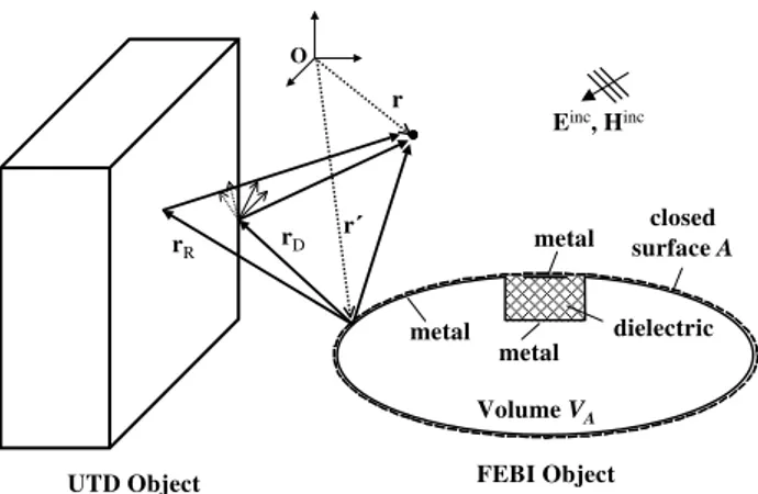
Abstract.The presence of arbitrarily shaped and electrically large objects in the same environment leads to hybridiza-tion of the Method of Moments (MoM) with the Uniform Geometrical Theory of Diffraction (UTD). The computation and memory complexity of the MoM solution is improved with the Multilevel Fast Multipole Method (MLFMM). By expanding thek-space integrals in spherical harmonics, fur-ˆ ther considerable amount of memory can be saved without compromising accuracy and numerical speed. However, un-til now MoM-UTD hybrid methods are restricted to con-ventional MoM formulations only with Electric Field Inte-gral Equation (EFIE). In this contribution, a MLFMM-UTD hybridization for Combined Field Integral Equation (CFIE) is proposed and applied within a hybrid Finite Element -Boundary Integral (FEBI) technique. The MLFMM-UTD hybridization is performed at the translation procedure on the various levels of the MLFMM, using a far-field approxima-tion of the corresponding translaapproxima-tion operator. The formu-lation of this new hybrid technique is presented, as well as numerical results.
1 Introduction
Exact numerical solutions of electromagnetic radiation and scattering problems with composite dielectric/metallic ob-jects are actually obtained with the Finite Element – Bound-ary Integral (FEBI) method. The involved integral equation (IE) is discretized by the Method of Moments (MoM) using Rao-Wilton-Glisson (RWG) basis functions and a Galerkin’s type approach (Rao et al., 1982). The resulting hybrid linear equation system is efficiently solved with iterative solvers in combination with appropriate preconditioning (Eibert, 2003).
Computation complexity and memory requirements of large scale MoM solutions for high frequencies increase rapidly with the dimensions of the objects. This prob-lem is overcome by the Multilevel Fast Multipole Method (MLFMM) resulting in low computation and memory com-plexity of O(NlogN ) (Coifman et al., 1993; Chew et al., 2001). Further saving of a considerable amount of memory
Correspondence to:A. Tzoulis ([email protected])
without compromising accuracy and numerical speed is achieved by expanding the FMM k-space integrals intoˆ spherical harmonics (Eibert, 2004).
Electrically large conducting objects are handled effi-ciently with ray-based high-frequency methods. Such meth-ods give accurate asymptotic solutions of the electromagnetic fields for objects with large dimensions as compared to the wavelength and no discretization is needed. The electromag-netic fields are described according to classical ray concepts of Geometrical Optics (GO) (Lo and Lee, 1993) and Uniform Geometrical Theory of Diffraction (UTD) (Kouyoumjian and Pathak, 1974).
Full electromagnetic coupling between dielectric arbitrar-ily shaped and UTD objects within a common environment is obtained with the hybrid FEBI-UTD method (Alaydrus et al., 2001), which is however restricted to conventional MoM formulations only with EFIE. In this contribution, the hybrid FEBI-UTD technique is extended by combin-ing MLFMM with UTD for CFIE. The MLFMM-UTD hy-bridization is performed in the translation procedure on the various MLFMM levels. The amplitudes of the UTD rays are determined according to the far-field MLFMM in Chew et al. (2001). Due to different ray directions for outgoing and incoming waves, appropriate interpolation and anterpolation routines must be applied to consider the UTD contributions. In the following, first the formulation of the FEBI-UTD for CFIE and after that the formulation of the MLFMM-UTD approach with expansion of thek-space integrals in sphericalˆ harmonics is presented. Finally, numerical results for various large scale examples are given.
2 Formulation
2.1 FEBI-UTD hybrid method
metal metal
metal
dielectric closed surface A
FEBI Object UTD Object
r
O
Einc, Hinc
Volume VA
r rR rD
Fig. 1.Hybrid FEBI-UTD concept.
The fields in the exterior regions are expressed with IE’s over the boundaries of the FEBI objects, being solved by a Galerkin-type MoM with RWG basis functions (Rao et al., 1982). The presence of UTD objects is taken into account by modifying the Green’s functions, as well as the incident fields of the IE’s, with additional high-frequency contribu-tions received at the testing or observation points, respec-tively (Alaydrus et al., 2001). In this contribution, 1st and 2nd order reflections and diffractions on flat structures are taken into account. The following formulations will be given for clarity only for 1st order mechanisms. The formulation for 2nd order mechanisms can be easily given in the same manner.
The UTD ray contributions are taken into account for the CFIE
Z(1−α)MF I E−αEF I E=0, (1) whereαis the combination parameter with values from 0 to 1 andZthe wave impedance of the considered solution space. The EFIE is given by
ˆ n×
ˆ n×
ZZ
A
−
GEJ,t ot(r,r′)·J
A(r′)
+ G−EM,t ot(r,r′)·M
A(r′)
da′+Einct ot(r)
+1 2MA(r)
=0 (2)
and the Magnetic Field Integral Equation (MFIE) by ˆ
n×
ZZ
A
−
GHM,t ot(r,r′)·M
A(r′)
+ −GHJ,t ot(r,r′)·J
A(r′)
da′+Hinct ot(r)
−1
2JA(r)=0, (3)
where
−
GE/HJ,t ot(r,r′)and −GE/H
M,t ot(r,r′)are the total Green’s functions of the electric or magnetic field due to electric and
Receiving group
UTD Object Source
group
O
Qn
r
m Q
r
Qr
Q
ˆ
i
k
,
ˆ r d
k n
r
m
r
r
nn
r
m n
d
Fig. 2.Hybrid MLFMM-UTD concept.
magnetic surface currents, respectively. Also, Einc t ot(r)and Hinct ot(r)are the total incident electric and magnetic fields at the observation pointr.
The total Green’s functions of the hybrid problem are the superposition of the Green’s functions of the direct coupling of the currents
−
GE/HJ /M(r,r′)and of
−
GE/HJ /M,U T D(r,r′)=X
s ARs
−
RE/Hs · −
GE/HJ /M(rRs,r′)
+X
v ADv
−
DE/Hv · −
GE/HJ /M(rDv,r′)
+ · · ·, (4)
which is the Green’s functions of the high-frequency ray-based fields due to UTD objects. ARs andADv are the di-vergence and phase factors for reflection and diffraction, re-spectively, and
−
RE/Hs and −
DE/Hv the dyadic reflection and diffraction coefficients for electric or magnetic field defined by basic GO (Lo and Lee, 1993) and UTD concepts (Kouy-oumjian and Pathak, 1974). Direct coupling is not taken into account if UTD objects lie between source and testing cur-rents.
Similarly, the high-frequency contributions of the incident electric and magnetic field at the observation pointrhave the form
EincU T D(r)=X s
ARs
−
REs ·Einc(rRs)
+X
v ADv
−
DEv ·Einc(rDv)
+ · · · (5)
and
HincU T D(r)= 1 Z ˆ kr×
X
s ARs
−
REs ·Einc(rRs)
+ 1 Z ˆ kd×
X
v ADv
−
DEv ·Einc(rDv)
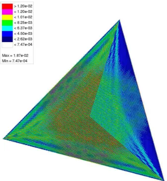
Fig. 3. Surface current density magnitude of trihedral 90◦corner reflector for 15 GHz.
-80 -60 -40 -20 0 20 40 60 80
-30 -20 -10 0 10 20 30 40 50 60
angle w.r.t. aperture
b
is
ta
ti
c
r
c
s
i
n
d
B
s
m
MoM PO
f = 64 GHz
22.1 Mio unknowns
Fig. 4.Bistatic RCS of trihedral 90◦corner reflector for 64 GHz.
where kˆr andkˆd are the propagation directions of the re-flected and diffracted rays, respectively. Again, no direct field contribution is taken into account if the observation point is in the shadow of an UTD object.
The MoM solution of the IE’s (1), (2) and (3) is achieved by expanding the surface currents in terms of RWG basis functionsβn using triangular surface meshes. The exterior fields are coupled with the interior ones via field continuity conditions at the boundaries of the FEBI objects. The result-ing hybrid linear equation system is solved by an iterative solution technique, using a multilevel iterative precondition-ing strategy (Eibert, 2003).
The matrix-vector product computations are accelerated by MLFMM. In order to retain low complexity in the hy-brid approach, UTD contributions are taken into account in the matrix-vector product MLFMM computations. In the fol-lowing, the MLFMM formulation for CFIE with expansion of thek-space integrals in spherical harmonics, as well as theˆ hybrid MLFMM-UTD formulation is presented.
2.2 MLFMM-UTD hybrid method
The hybrid MLFMM-UTD concept is shown in Fig. 2. The source groupn′and the receiver groupm′belong to the FMM model of the FEBI object at a specific level. The CFIE matrix elements in FMM representation can be written as (Coifman et al., 1993; Chew et al., 2001)
ZCF I Emn,J = −c1
Z
Z ∼
β∗m(k)ˆ ·TL(kˆ· ˆrm′n′)
−
I− ˆkkˆ·β∼n(k) dˆ kˆ2
+c2 Z
Z
ˆ
k×∼α∗m(k)ˆ
·TL(kˆ· ˆrm′n′) ∼
βn(k) dˆ kˆ2 (7)
and ZCF I Emn,M = +c3
Z
Z
ˆ k×
∼
β∗m(k)ˆ ·TL(kˆ· ˆrm′n′) ∼
βn(k) dˆ kˆ2
+c4 Z
Z ∼
α∗m(k)ˆ ·TL(kˆ· ˆrm′n′)
−
I− ˆkkˆ· ∼
βn(k) dˆ kˆ2
(8) wherec1 = jωµ4πα,c2 = j Z04kπ(1−α),c3 = j4kπαand
c4=j Z0ωε4π(1−α). Further, ∼
βm(k)ˆ =
ZZ
A
βm(r)ejk·rmm′da (9)
and
∼
αm(k)ˆ =
ZZ
A
αm(r)ejk·rmm′da (10)
are thek-space representations of the basis functions andˆ
TL(kˆ· ˆr)= L
X
l=0
(−j )l(2l+1)hl(2)(kr)Pl(kˆ· ˆr) (11)
is the translation operator. Also, h(l2) is the second kind spherical Hankel function of degree l, Pl is the Legendre polynomial of degreeland * denotes complex conjugation. The MLFMM is implemented with memory efficiency by ex-panding the representations
∼
βm(k)ˆ of the basis functions in spherical harmonics according to
∼
βm(k)ˆ = P
X
p=0
p
X
q=−p
0 2 4 6 8 10 12 14 16 20
30 40 50 60 70 80 90 100
MoM Mie
rc
s
i
n
d
B
s
w
theta in degree D = 1 m = 146.7
15.3 Mio unknowns
CFIE with ✁ = 0.5
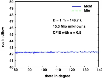
Fig. 5. RCS near forward direction of conducting sphere with diameterD=1 m=146.7λby CFIE solution.
where Ypq(ϑ, ϕ)=
s
(2p+1)(p−q)! 4π(p+q)! P
q
p(cosϑ )ej qϕ, (13) are the orthonormalized spherical harmonics (Harrington, 1961). Also, Pqpis the associated Legendre polynomial of de-greepand orderq. According to this approach, the matrix-vector product computations within the iteration loop of the iterative solver are performed by first aggregating all expan-sion coefficients at the center of each MLFMM group at the finest level. After that, the outgoing waves are computed at the quadrature points for all groups on the finest MLFMM level. The translations of outgoing waves into incoming waves as well as the aggregations and disaggregations be-tween different MLFMM levels including interpolation and anterpolation are performed as in standard MLFMM using the numerical quadrature samples. However, when all in-coming waves are collected in a certain group on the finest level, the spherical harmonics expansion
TL(kˆ· ˆrm′n′)
−
I− ˆkkˆ· ∼
βn(k)ˆ = P
X
p=0
p
X
q=−p
gnpqYpq(ϑ, ϕ)(14)
is carried out and by utilizing the orthogonality of the spher-ical harmonics, the closed integral over the Ewald sphere is simplified to the series
Zmn= −j ωµ
4π P
X
p=0
p
X
q=−p
(fmpq)∗·gnpq. (15)
The number of expansion coefficients needed with this ap-proach is in general less than the corresponding number of quadrature samples for numerical integration in thek-space,ˆ resulting in saving of memory requirements.
The ray contributions due to UTD objects are taken into account in the MLFMM matrix-vector product computations
80 90 100 110 120 130 140
40 41 42 43 44 45 46 47 48 49 50
rc
s
i
n
d
B
s
w
theta in degree
MoM Mie
D = 1 m = 146.7
15.3 Mio unknowns
CFIE with ✁ = 0.5
Fig. 6. RCS near backward direction of conducting sphere with diameterD=1 m=146.7λby CFIE solution.
by assuming that the ray path from the source group to the UTD objectrQn′ is much greater than the dimensions of the
group itself. This means, that only onekˆdirection is needed to express the radiated field from the source group. Assum-ing far-field conditions, the scalar Green’s function from the source current to the local point on the UTD object is ex-pressed with the far-field MLFMM approximation
G(rQ,r′)=
e−j k|rQ−r′|
|rQ−r′|
=ejki·rnn′TF F
L , (16)
whereki =kkˆi,kˆi = ˆrQn′ is the direction of ray incidence
and TLF F = e
−j krQn′ rQn′
(17) is the associated far-field translation operator (Chew et al., 2001). Thus, the translation of the high-frequency contri-butions is performed only for the direction of ray incidence
ˆ
ki. The received high-frequency fields are taken into account only for the reflectionkˆr or diffractionkˆddirections from the local point on the UTD object to the receiver groups. The fol-lowing MLFMM-UTD formulations are given for simplicity for the case of the EFIE contributions in (7). However, they apply to all contributions in (7) and (8) as well. The ray contributions of the matrix elements of the hybrid MLFMM-UTD approach can be written as
ZEF I Emn,J,U T D= −jωµ
4π
∼
β∗m(kˆr)·
X
s ARs
−
REs TLF F· −
I− ˆkrkˆi
· ∼
βn(kˆi)
−jωµ 4π
∼
β∗m(kˆd)·
X
v ADv
−
DEvTLF F·−I− ˆkdkˆi
· ∼βn(kˆi)
+ · · ·, (18)
x y z
PEC
PEC 26
40 40
Einc f = 30 GHz
|E0|=100 V/m
Fig. 7. Conducting cone cylinder in front of conducting plate at distanceλ.
0.12 0.125 0.13 0.135 0.14
0 50 100 150 200 250
x(m)
|Eto
t
|(
V
/m
)
FEBI-MLFMM 6.5 h, 1600 MB RAM FEBI-MLFMM-UTD 3 h, 360 MB RAM
Fig. 8.Electric field in direction of propagation for conducting cone cylinder in front of conducting plate.
In the numerical implementation of MLFMM, a limited number of sampling points is used to evaluate thek-spaceˆ integrals. In general, the ray directions of incidencekˆi, re-flectionkˆr or diffractionkˆd do not match with any of these sampling points. For this reason, the required direction of in-cidence must be interpolated from the neighboring sampling points. Similarly, after reflection or diffraction, the appro-priate ray direction must be anterpolated to the neighboring sampling points.
3 Numerical examples
In this section, numerical results of various large scale ex-amples are presented. First, a trihedral 90◦conducting cor-ner reflector with 1.4 m edge length has been computed, as
Fig. 9.Magnitude of surface current density on conducting cylindri-cal parabolic reflector with X-band horn excitation forf=10 GHz.
(°)
|E
✁|(
d
B
)
FEBI-MLFMM 11.5 h, 1900 MB RAM FEBI-MLFMM-UTD
10 plates, 3 h, 150 MB FEBI-MLFMM-UTD 6 plates, 2 h, 150 MB
-180 -150 -120 -90 -60 -30 0 30 60 90 120 150 180 -70
-60 -50 -40 -30 -20 -10 0 10 20
FEBI-MLFMM-UTD 20 plates, 7.5 h, 150 MB
zy-plane
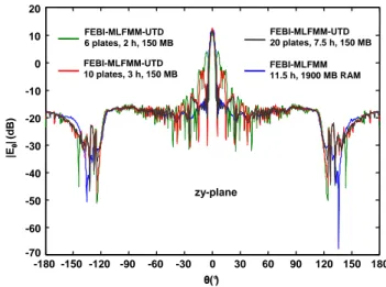
Fig. 10.Co-polar radiation pattern on principal E-plane of conduct-ing cylindrical parabolic reflector with X-band horn excitation for
f=10 GHz.
shown in Fig. 3. In the same figure, the magnitude of the surface current density on the corner reflector can be seen, computed for 15 GHz, using a triangular surface mesh. For the same corner reflector, RCS computations have been car-ried out for 64 GHz, using H-polarized plane wave excita-tion with normal incidence. In this case, the reflector was discretized with 22.1 Million unknowns and the computa-tion time of the solucomputa-tion was about 122 h on an Opteron 2.2 GHz CPU with about 28 GB memory requirements. In Fig. 4, the co-polar bistatic RCS can be seen, compared to a PO solution. It is noticed, that to our knowledge this com-putation is currently the world-wide largest MoM solution performed on a single CPU.
obtained with FEBI for CFIE withα=0.5. In Figs. 5 and 6, the computed RCS is shown, for small regions near forward and backward direction, respectively. The numerical results are compared to the corresponding Mie-series analytical so-lution. It can be seen, that numerical results have excellent agreement with the exact analytical solution. Especially at backward direction, very small ripple of the numerical solu-tion can be seen.
Next example is the problem of a conducting cone cylin-der in front of a conducting plate at distanceλ, as shown in Fig. 7. Two computations have been carried out. First, both objects where discretized with triangular surface mesh, re-sulting in 630 628 unknowns. In the second computation, the same surface mesh was used for the cone cylinder and the plate was treated by UTD. In this case, the number of un-knowns was 150 492. In Fig. 8, the calculated electric field in direction of propagation for both computations is shown. In the same figure, computation time and memory require-ments on an AMD Athlon 2000+ PC are shown as well. It can be seen, that the hybrid FEBI-UTD results agree very well with the exact numerical FEBI solution, needing much less computation time and memory requirements.
Last example is a conducting cylindrical parabolic reflec-tor with X-band horn excitation forf=10 GHz, as shown in Fig. 9. In the same figure, the magnitude of the surface cur-rent density on both objects can be seen, using a triangu-lar surface mesh for both objects with 830 280 unknowns. For the hybrid FEBI-UTD computation, the reflector was ap-proximated by flat plates and computations were done for 6, 10 and 20 plates. In Fig. 10, the co-polar radiation pattern on the principal E-plane for all computations is shown. In the same figure, the computation time and memory require-ments on an AMD Athlon 2000+ PC are shown as well. It can be seen, that for 6 and 10 plates the hybrid FEBI-UTD solution presents significant side lobes. For 20 plates, the so-lution shows very good agreement with the exact numerical FEBI solution, needing less computation time and memory requirements.
4 Conclusions
In this contribution, the hybrid FEBI-MLFMM-UTD method for numerical radiation and scattering computations was pre-sented. Due to memory efficient implementation of the MLFMM, large scale numerical computations can be carried out. The FEBI-UTD hybridization allows optimum treatment of problems including arbitrarily shaped composite dielec-tric/metallic objects and electrically large conducting objects of simple shape in the same environment. Low computa-tion complexity and memory requirements are retained in the hybrid FEBI-UTD approach, due to MLFMM-UTD combi-nation. The MLFMM-UTD hybridization is performed in the translation procedure on the various MLFMM levels, us-ing a far-field approximation of the appropriate translation operator. The hybrid FEBI-UTD formulation for CFIE, as well as the formulation of the MLFMM-UTD combination
with expansion of thek-space integrals in spherical harmon-ˆ ics was presented. Finally, numerical results for various large scale antenna and scattering problems were given.
References
Alaydrus, M., Hansen, V., and Eibert, T. F.: Hybrid2: Combining the three-dimensional hybrid finite element – boundary integral technique for planar multilayered media with the uniform geo-metrical theory of diffraction, IEEE Trans. Antennas Propagat., vol. 50, no. 1, 67–74, Jan. 2002.
Chew, W. C., Jin, J.-M., and Michielssen, E.: Fast and efficient algorithms in computational electromagnetics, Boston: Artech House, 2001.
Chew, W. C., Cui, T. J., and Song, J. M.: A FAFFA-MLFMA al-gorithm for electromagnetic scattering, IEEE Trans. Antennas Propagat., vol. 50, no. 11, 1641–1649, Nov. 2002.
Coifman, R., Rokhlin, V., and Wandzura, S.: The fast multi-pole method: A pedestrian prescription, IEEE Antennas Prop-agat. Mag., vol. 35, no. 3, 7–12, Jun. 1993.
Eibert, T. F.: Advances in hybrid finite element – boundary in-tegral modelling of three-dimensional radiation and scattering problems, Intern. ITG Conf. on Antennas, 157-160, Berlin, Sep. 2003.
Eibert, T. F.: A multilevel fast multipole method with spherical harmonics expansion of thek-space integrals, URSI EM-Theory Symposium, Pisa, Italy, 150–153, May 2004.
Harrington, R. F.: Time harmonic electromagnetic fields, New York: McGraw-Hill, 1961.
Kouyoumjian, R. G. and Pathak, P. R.: A uniform geometrical the-ory of diffraction for an edge in a perfectly conducting surface, Proc. IEEE, vol. 62, no. 11, 1448–1461, Nov. 1974.
Lo, Y. T. and Lee, S. W.: Antenna handbook, vol.1, Chapman & Hall, New York, 1993.
Rao, S. M., Wilton, D. R., and Glisson, A. W.: Electromagnetic scattering by surfaces of arbitrary shape, IEEE Trans. AP, vol. 30, 409–418, May 1982.