PLC Based Automatic Multistoried Car Parking System
Swanand S .Vaze*, Rohan S. Mithari**, Sanjay
T. Sanamdikar***
*(Department of Instrumentation and control, University of Pune, India)**(Department of Instrumentation and control, University of Pune, India)
***(Department of Instrumentation and control, P.D.E.A's College Of Engineering, University of Pune, India)
ABSTRACT
This project work presents the study and design of PLC based Automatic Multistoried Car Parking System. Multistoried car parking is an arrangement which is used to park a large number of vehicles in least possible place. For making this arrangement in a real plan very high technological instruments are required. In this project a prototype of such a model is made. This prototype model is made for accommodating twelve cars at a time. Availability of the space for parking is detected by optical proximity sensor which is placed on the pallet. A motor controlled elevator is used to lift the cars. Elevator status is indicated by LED which is placed on ground floor. Controlling of the platforms and checking the vacancies is done by PLC. For unparking of car, keyboard is interfaced with the model for selection of required platform. Automation is done to reduce requirement of space and also to reduce human errors, which in-turn results in highest security and greatest flexibility. Due to these advantages, this system can be used in hotels, railway stations, airports where crowding of car is more.
Keywords
-
PLC based, Pneumatic, Prototype model, Highest security, Greatest flexibility, Reduce human errorsI.
INTRODUCTION
Multistoried car parking system is very essential in the modern world where number of vehicles is increasing day by day and parking spaces in public as well as private areas are not sufficient. This project deals with a similar problem and as a solution, the system is developed wherein anyone can park more number of vehicles in a smaller space. Also by such arrangement, parking will be done systematically. Unlike any other multistoried parking, this parking system is semicircular in shape due to which availability of space for parking gets increased. Since it is completely automated system human errors are negligible and hence system is more reliable. This
project makes use of a „DVP 14 SS „ PLC for
controlling purpose, simple DC geared motors for circular as well as vertical movements of lift, Optical proximity sensor to sense entry of car and Relay board to drive the motors. High torque motor is required for rotational movement of lift. Three pneumatic cylinders having stroke length 50mm each are used to move the pallet which is mounted inside the lift. As stroke length of cylinder increases, cost and size of cylinder also increases. Hence instead of using one cylinder having stroke length 100mm, three cylinders are used. All three cylinders are actuated simultaneously with regulated pressure of 3psi.Penumatic silencers are used for regulating the pressure.
1
. Review of existing system
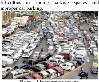
Number of cars is increasing day by day
which results in many problems such as
difficulties in finding parking spaces and
improper car parking.
Figure 1.1 Improper car parking
1.1 Difficulty in finding vacant spaces
Quickly finding a vacant space for parking
of car especially on weekend or public holidays
is very difficult task. Stadium or shopping malls
are crowed on holidays and weekends which
results into insufficient area for car parking.
1.2 Improper parking
Improper car parking is, when a car is not
parked correctly in allocated parking area. Due
Improper car parking the space allocated for
parking will not be used in proper manner. This
may create traffic congestion.
II.
Escalator mechanism
2.1 Purpose of escalator
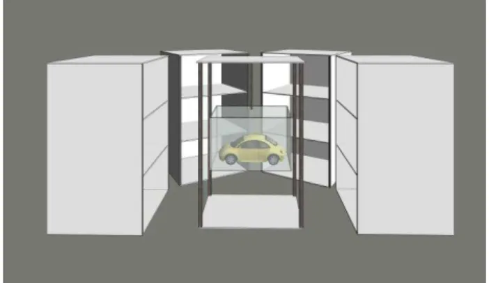
This multistoried car parking system is semicircular in shape. There are four buildings available for parking. Each building is having three floors. Hence car needs to move upward for first and second floor parking. Escalator is the best solution for moving the car up and down. This escalator is having vertical as well as circular movement to park the car in appropriate manner.
2.2 Components used in escalator
Various components are used for precise, movement of the escalator. Relay board having four relays, eight limit switches and DC geared motors are some essential components used for this purpose.
2.2.1 Relay board
Relay board is placed to drive the outputs of PLC. It contains 4 relays. Relays are used to provide power to 12volt DC geared motors. Voltage required to drive the DC motor is 12V DC. PLC gives 24V DC output. Hence to drive the 12V motor by PLC, relay interfacing is essential. In this project, movement of escalator is in both forward and reverse direction. Hence single DC motor is driven by two relays. Figure 2.1 shows relay and motor interfacing connection diagram
Figure 2.1 Relay connection
2.2.2 DC motor
This project makes use of two DC geared motors.[2] First motor is high torque 60 rpm motor and second is 5 rpm low torque motor.
High torque 60 rpm motor is used for vertical movement of escalator. Since the weight of escalator is very high, torque required to lift the escalator is also very high. This motor is mounted on the top of the assembly. Since this is prototype model, simple pulley mechanism is used for vertical movement of the escalator. A mechanical pulley is coupled with the shaft of motor. Motor is connected to PLC through the relay board.
Rotational movement of the escalator is achieved by another DC geared motor. Low torque 5 rpm DC motor is used for this purpose. This motor is mounted
on the bottom side of the escalator. Shaft of this motor is attached to the gear mechanism. Spur type gearing mechanism is done for steady and vibration free movement of escalator.
2.2.3 Limit switches
The movement of the escalator is terminated safely with the help of Limit switches. Eight limit switches are used for precise movement control of escalator. Out of eight, three limit switches are used to regulate vertical motion of escalator. Since building is three floor building, each limit switch is mounted on each floor to ensure correct stopping of lift. Limit switch mounted on ground floor is normally open while limit switches on first and second floors are initially in normally closed position.
Remaining five limit switches are used to restrict rotational movement of escalator. Those five limit switches are mounted on each building. All five limit switches are initially in normally closed position. When escalator comes in front of the selected building, limit switch mounted on that building turns to normally open position as a result motor stops rotating.
2.3 Working of escalator
Entering of car inside the Escalator is ensured by the optical proximity sensor which is mounted on the escalator. Once car is entered in the escalator, other proximity sensors which are mounted on the each floor start sending their occupancy status to the PLC. Address of vacant floor is provided to the escalator by PLC. Escalator moves up using simple DC geared motor. A pulley is attached to the shaft of the motor and this motor pulls escalator upwards. This DC motor is bi-directional motor and hence it is driven with the help of two relays. Once this Escalator moves upward, pallet in the lift moves circularly for appropriate parking position. This circular motion of pallet is controlled precisely by limit switch. High torque DC geared motor is used to rotate the pallet. Once car gets parked in the slot, escalator comes back to its original position.
III.
Pneumatic Mechanism
3.1 Ways of pushing the car
Once escalator has reached to the designated building and floor, the pallet on which car is mounted needs to push onto the designated slot. Pallet can be pushed by three ways: Using motor or by Hydraulic mechanism or by Pneumatic mechanism.
3.1.1 Motor system
DC motor can be used for pushing the pallet. Since pallet weight is very high, motor having very high torque and high rpm will be required. Also to regulate the speed of motor is very difficult task. Due to high torque, system may suffer through lot of jerks and vibrations. This may damage the system hence this method is ruled out.
3.1.2 Hydraulic mechanism
Pallet of the escalator can be pushed using hydraulic cylinders. For smoother and strokes free movement hydraulic is best option. Since hydraulic system is very bulky it is not suitable for this project. Hydraulic oil and hydraulic power packs are very expensive. Also in hydraulic system leakage of oil may occur which will create some problem in functioning of system. Hence this method is also ruled out.
3.1.3 Pneumatic mechanism
Pneumatic system is the best solution for this project. Fuel i.e. air is the cheapest fuel hence cost of whole assembly is also lesser. Regulating pneumatic pressure is easier than regulating hydraulic pressure. Hence among all the available options, pneumatic is reliable and cost effective solution to push the pallet.
3.2 Working of pneumatic system
Assembly of pneumatic cylinders is as shown in the figure 3.1. This project requires three pneumatic cylinders. Total stroke length required to push the pallet is 100 mm. A pneumatic cylinder having stroke length 100 mm is costlier than three cylinders. Also size of cylinder also increases as stroke length increases. Hence instead of using one pneumatic cylinder, three cylinders having stroke length 50mm are used.
This assembly of three cylinders is shown in figure 3.2. Cylinder A and cylinder B are coupled with each other with the metal strip. This metal strip is fixed at the end of cylinder strokes. Cylinder C is mounted exactly on the center of the metallic strip.
These pneumatic cylinders are connected to 3/2
direction control valve (DCV). [3] A direction
control valve receives the signal from PLC and
supplies proportionate air supply to cylinders.
All cylinders get actuated at the same time and
works on the same pressure. Required pressure
for actuation of cylinder is 3 psi. Two pneumatic
silencers are used at two inlet ports of DCV.
Pneumatic silencers don‟t allow excess pressure
to enter into the cylinder. This gives protection
against excessive pressure to enter into the
system.
Figure 3.1 Isometric view
Figure 3.2 Front view
3.3 Specification of cylinder
SRNO.
NAME SPECIFICATION
1 Cylinder Diameter 20 mm
2 Stroke Length 50 mm
3 Input Pressure 3 psi
Table 3.1
IV.
Programmable Logic
Controller(PLC)[1]
4.1 Selection of PLC
This project makes use of ” DELTA DVP 14 SS” PLC amongst all those PLCs [4]. The main advantage of this PLC is it is cost effective. This PLC uses simple programming language. WPLSoft_2.36 is the software used for the programming of this PLC. Another advantageous function of this PLC is inputs and outputs are expandable. This project work deals with 11 inputs and 5 outputs. Hence external IO module is required to fulfill the requirement of inputs and outputs. DVP 16 SP is the digital IO module used along with the PLC. This project does not use any analog signal hence only digital expansion card is used.
4.2 Role of PLC
The PLC works as a controller for this project. PLC is used to control the movement of escalator and working of pneumatic mechanism. During escalator movement control PLC receives the signal from the optical proximity sensors. Priorities for selection of building and floor are assigned to PLC using PLC programming. Then as per predefined priorities PLC decides the floor for parking. Once the floor is decided PLC sends output signal to motor driver relay. Motor brings the escalator near to the assigned building and floor.
After completion of motor movement PLC starts operating pneumatic mechanism. PLC sends output signal to 3/2 Direction Control Valve which actuates three pneumatic cylinders. Pneumatic cylinder pushes the car inside the parking slot. Acknowledgement signal for completion of parking is provided to PLC by optical proximity sensor. After receiving the signal from proximity sensor PLC gives the return command to Direction Control Valve and motor to move back to original position.
4.3 PLC specifications
DVP 14 SS SR
NO.
NAME SPECIFICATION
1 Dimensions 25 x 90 x 60 mm
2 Supply Voltage 24 V DC
3 Digital Input 8
4 Digital Output 6
5 Power Consumption 3.5W
Table 4.1
DVP 16 SP SR
NO.
NAME SPECIFICATION
1 Dimensions 25 x 90 x 60 mm
2 Supply Voltage 11-25 V DC
3 Digital Input 8
4 Digital Output 8
Table 4.2
V.
Manual mode
PLC is introduced in the project to make the project automatic. This project can work individually without using PLC. This manual mode of operation uses two DPDT switches and eight toggle switches. Motor contacts are connected to the DPDT switches for manual operation of motor. Since motor is working in forward and reversed direction DPDT switches are selected.
Similarly contacts from limit switches are given to the toggle switches to operate the limit switch manually. A mushroom switch is used as emergency stop switch to stop the process during emergencies.
VI.
Overall working
Figure 6.1 Overall working of project
When car is entered in the pallet of escalator, it is detected by the optical proximity sensor and it gives the 24 v signal to the PLC. After receiving the signal, PLC checks the other sensor status and select the building no and the floor no (Ground, 1st, 2nd floor) as per the programming of PLC. After detection of parking slot, PLC gives the signal to relay board. Relay board is used as a driver to drive low voltage dc motor. High torque dc motor pulls the lift in upward direction with the help of pulley. This motor brings the lift in front of designated floor. When lift reach to the parking area then the PLC checks the status of the motor driver and gives the signal to the pneumatic system. Pneumatic system pushes the pallet in the parking area. When the car is parked inside the parking area then the optical sensor placed inside the parking area change its status and gives the signal to the PLC. Then PLC again sends the signal to the motor driver for reverse action of motor and pneumatic system to regain original position.
VII.
CONCLUSION
Thus system designed is very precise and very easy in handling. This system is advantageous for commercial as well as residential purpose. The components used are readily available which makes construction very easy. The structure is compact which allows the system to be installed on any platform.
REFERENCES
[1] http://en.wikipedia.org/wiki/Programmable
_logic_controller
[2] B. L. Theraja, A. K. Theraja, “A Textbook of Electrical Technology”,Sultan Chand & Sons, 1st Multicolour Edition, Volume II, 2005, ISBN 8121-92437-5