www.adv-sci-res.net/11/55/2014/ doi:10.5194/asr-11-55-2014
© Author(s) 2014. CC Attribution 3.0 License.
MASC – a small Remotely Piloted Aircraft (RPA) for wind
energy research
N. Wildmann1, M. Hofsäß2, F. Weimer3, A. Joos3, and J. Bange1
1Center for Applied Geosciences, Eberhard-Karls-University Tübingen, Tübingen, Germany
2Stuttgart Wind Energy (SWE) at the Institute for Aircraft Design (IFB), University of Stuttgart, Stuttgart,
Germany
3Institute of Flight Mechanics and Control, University of Stuttgart, Stuttgart, Germany
Correspondence to:N. Wildmann ([email protected])
Received: 14 January 2014 – Revised: 29 March 2014 – Accepted: 9 May 2014 – Published: 27 May 2014
Abstract. Originally designed for atmospheric boundary layer research, the MASC (Multipurpose Airborne Sensor Carrier) RPA (Remotely Piloted Aircraft, also known as Unmanned Aerial Vehicle, UAV) is capable of making in-situ measurements of temperature, humidity and wind in high resolution and precision. The autopilot system ROCS (Research Onboard Computer System) enables the aircraft to fly pre-defined routes between
way-points at constant altitude and airspeed. The system manages to operate in wind speeds up to 15 m s−1safely. It
is shown that a MASC can fly as close as one rotor diameter upstream and downstream of running wind turbines at these wind speeds and take valuable data of incoming flow and wake. The flexible operation of an RPA at the size of a MASC can be a major advantage of the system compared to tower measurements and remote sensing in wind energy research. In the project “Lidar Complex” comparisons of RPA measurements with lidar systems and tower measurements are carried out at two different test sites. First results, including turbulence and wake measurements, from a campaign in autumn 2013 are presented.
1 Introduction
Small Remotely Piloted Aircraft (RPA, also known as Un-manned Aerial Vehicle, UAV) have been increasingly used in atmospheric sciences throughout the last decade. In atmo-spheric boundary layer (ABL) research, systems like SUMO (Reuder et al., 2009) for vertical sounding of the atmosphere,
or the M2AV (Spieß et al., 2007; Martin et al., 2011), which
is additionally capable of measuring turbulent fluxes of sen-sible heat (Martin and Bange, 2014) and individual turbulent outbursts like entrainment (Martin et al., 2014), have become valuable instruments for data collection. Also outside Europe similar systems are operated, as presented in Thomas et al. (2012) and Bonin et al. (2013). Boundary-layer research has become increasingly interesting for the wind-energy commu-nity, since efficiency of wind turbines is directly related to the effects in the boundary layer. Therefore the same (Reuder and Jonassen, 2012) or similar (Subramanian et al., 2012) RPA that have been used for fundamental boundary-layer
re-search have recently been applied in wind-energy rere-search. The thermal stratification of the atmosphere, which can be investigated with vertical profiles collected by RPA, has ef-fects on wind shear and turbulence. Both of these efef-fects have large impact on the efficiency and fatigue of wind turbines. Simple analysis of wind sites assuming the wind profiles of thermally neutral stratification neglect these effects and can lead to a wrong estimation of the risks associated with the deployment of a wind energy converter (WEC). While large-eddy-simulation (LES) is used to study the effects of turbu-lence in detail (e.g. Zhou and Chow, 2012; Wu and Porté-Agel, 2012, 2011), measurements are necessary to validate and initialize these studies. Small RPA as a flexible and cost-effective tool can serve this purpose. It is shown in this paper how the small RPA MASC (Multi-purpose Airborne Sensor Carrier), which was developed at the University of
Tübin-gen, based on the experiences with the M2AV, is now used
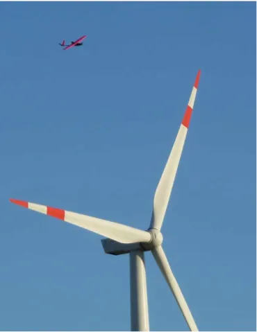
Figure 1.Research RPA MASC in front of a Kenersys K110 WEC (picture taken by Joe Smith, University of Tübingen).
Figure 2.Research RPA MASC.
2 System description
MASC is a small fixed wing RPA with one electrical pusher engine (see Fig. 2). Three different wing sizes exist for the aircraft ranging from 2.60 to 3.40 m. With minimum battery and payload the total weight of the MASC is less than 5 kg. Flight time in this configuration is limited to approximately 15 min. The endurance can be increased up to one hour by adding more batteries. The total weight of the system will than exceed 7.5 kg. For take-off, a bungee launch procedure
Table 1.Characteristics of the MASC RPA.
wing span 2.60 m, 3.00 m or 3.40 m
rudder configuration ailerons, flaps, v-tail weight 5–7.5 kg, depending on battery load
payload max. 1.5 kg
endurance 15–60 min, depending on battery load
cruising speed 24 m s−1
propulsion electrical pusher motor
take-off bungee launch
Table 2.Typical ROCS autopilot performance.
tracking accuracy ±5 m altitude precision ±2 m airspeed precision ±1 m s−1
is performed at the University of Tübingen. The alternative of a landing gear limits take-off and landing spots to flat run-ways and would also increase total weight of the aircraft. For slow and safe landings the MASC is equipped with flaps to decelerate before touch down. Table 1 summarizes the char-acteristics of the MASC aircraft.
2.1 Autopilot
The ROCS (Research Onboard Computer System), devel-oped at the Institute of Flight Mechanics and Control (iFR) at the University of Stuttgart, is a autopilot system with waypoint navigation capabilities. Its embedded linux sys-tem, enhanced with an FPGA (Field Programmable Gate Ar-ray) chip, provides computing power for complex navigation tasks. In the field of meteorological measurements, only a fraction of the possibilities are used so far.
The basic sensor suite of the ROCS autopilot consists of a single-channel GPS receiver, a micro-electro-mechanical-system (MEMS) inertial measurement unit (IMU) as well as barometric and differential MEMS pressure transducers. From this, position, velocity, and attitude of the UAV are es-timated using a extended Kalman Filter (EKF). The estimates are then used in the guidance process to keep the UAV on the desired flight track. An overview of performance character-istics is given in Table 2.
2.2 Meteorological measurement system
Table 3.MASC measurement equipment characteristics.
variable sensor type accuracy
temperature PT100 and thermocouple ±0.5 K humidity capacitive sensor P14-Rapid ±3 % RH pressure barometer HCA-BARO ±0.5 hPa wind five hole probe, plus GPS/INS ±0.5 m s−1
for live observation on a groundstation laptop is provided by the system.
There are two temperature sensors installed in parallel – a thermocouple and a resistance thermometer - both in a fine wire design. A detailed description of these sensors can be found in Wildmann et al. (2013). Detailed information on the flow probe setup is presented in Wildmann et al. (2014). In both papers the data logger AMOC is also described in more detail. The complementary measurement of ground speed and orientation of the aircraft with the commercial In-ertial Navigation System (INS) IG-500N by SBG systems enables in-situ wind measurement. The commercial capaci-tive humidity sensor P14 Rapid by Innovacapaci-tive Sensor Tech-nology (IST) with custom electronics and a MEMS barom-eter (HCA-BARO by Sensortechnics) complete the thermo-dynamic measurement.
3 Project “Lidar Complex”
The project “Lidar Complex” was initiated by the research network “WindForS” (www.windfors.de), based in Southern Germany. The goal of the project is to establish lidar technol-ogy for wind energy plant site evaluation in complex terrain. Additional goals are the comparison of different measure-ment techniques and the validation of wind field models in terrain that does not conform to IEC61400. It is planned to design a turbulent wind field generator, fed by real measure-ment data, which can be used to analyse WEC behaviour. An experiment was carried out in October 2013 in flat terrain in Northern Germany to establish a baseline for the comparison of all instruments. In spring 2014, experiments at the test site in complex terrain in the Swabian Alb will be extended.
3.1 Test site Grevesmühlen/Baltic Sea
The test site in Grevesmühlen, located approximately 15 km upcountry of the coast of the Baltic Sea in Germany, was included in the project “Lidar Complex” as a reference site for measurements in a terrain with a low complexity level. Although there are several small areas of sparse woods and different crop types, the orography is flat and the terrain con-forms with IEC standards. The site has three WECs (Kener-sys K110 2.4 MW, K100 2.5 MW and K82 2.0 MW) placed in a triangle with 1.2–1.5 km distance to each other. In main wind direction, which is from the south-west, a measurement
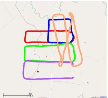
Figure 3. Extracts of recorded flight tracks at test site Greves-muehlen. Vertical profiles up to 500 m are measured with a square pattern (blue). Rectangular “racetrack” patterns at constant altitude serve to measure turbulence parameters upstream (purple), down-stream (red) and between the wind turbines (green, orange). The position of the WECs is depicted as crosses in the map, the mea-surement tower as a black triangle.
tower is placed in front of one of the WECs. The tower is equipped with a sonic anemometer at hub height, three cup anemometers, three wind vanes, a rain sensor, a temperature sensor at hub height, a barometric pressure sensor and a hu-midity sensor. Besides a measurement tower there are also two lidar systems installed in the vicinity of this particular WEC. One of them, a Leosphere “Windcube v2” pulsed lidar, is situated close to the measurement tower, looking upwards and the other one is a forward looking, nacelle-based lidar that was provided by SWE (Rettenmeier et al., 2010; Peña et al., 2013). Figure 3 shows several different flight paths that were performed at this site in a four day campaign from 21 to 24 October 2013.
3.2 Test site Schnittlingen/Swabian Alb
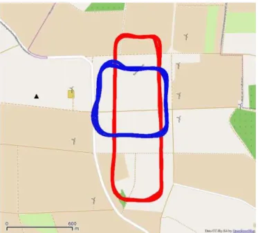
Figure 4.Extracts of recorded flight tracks at test site Schnittlingen. Vertical profiles up to 500 m were measured with a square pattern (blue). Rectangular “racetrack” patterns at constant altitude serve to measure turbulence parameters (red). The position of the WECs can be seen from the OpenStreetMap layer, the measurement tower is depicted as a black triangle.
The wind field is highly influenced by the so-called “Alb-trauf”, which is an approximately 100 m steep escarpment about 2 km upstream in the main wind direction of the test site. One research goal of the project is to investigate the im-pact of the escarpment on the wind field.
4 Results
4.1 Flight performance in high wind speeds and in the wake of wind turbines
A short test experiment in late spring 2013 at the test site in the Swabian Alb was used as a proof of concept. Experience was gained about optimal flight strategies and quality of sen-sor data in the immediate vicinity of WECs.
MASC showed good performance throughout the exper-iment. The maximum wind speeds that were found during
these days were 12 m s−1. More flights were conducted in
October 2013 at the site in Grevesmühlen. Again, MASC was able to take data up- and downstream of a wind turbine
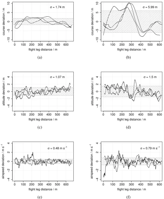
in wind speeds up to 15 m s−1. Figure 5 shows the precision
of the autopilot controlled flight in the wake of a WEC in comparison to flight legs in the undisturbed boundary layer. While in all three depicted variables (course, altitude and air-speed) the presence of the wake can be observed at around 300 m flight leg distance, the aircraft never entered a criti-cal state. The largest deviations from the demand values can be found in the course with up to 10 m deflection. This
be-haviour is intended, since course deviations are least critical for meteorological measurements and the autopilot controller was tuned accordingly.
4.2 Comparative measurements upstream
In the experiment in Grevesmühlen, a wide variety of mea-surement equipment was present as described in Sect. 3. A first analysis of the data was carried out to show if system-atic errors between the different sensors could be obseserved. The best agreement of all measurements can be found be-tween ground-based lidar and tower-based sonic anemometer measurements. The reason is, that these measurements have the least spatial offset and thus measure the same air mass at the same time. The time series of sonic measurements in the
observed period has a standard deviation of approx. 1 m s−1.
Deviations among the measurement systems are within this range, so that a good agreement can be assumed. Figure 6 shows data from sonic anemometer measurements on the tower, data from the nacelle-based lidar, the ground-based li-dar and RPA measurements. Since RPA measurements are not point measurements, the sections of straight and level flight (legs) that were approximately 800 m long were ex-tracted and averaged for the comparison. The error bars show the standard deviation of the measurements within these legs. It is evident that a perfect agreement between the sensors is not possible, because spatial and temporal biases can have large effects on the instantaneous wind measurement in the turbulent boundary layer. Given these conditions, the agree-ment is a good basis for further investigations on the wind field at the site in Grevesmühlen and for the next experiments in complex terrain. The good accuracy of wind-vector mea-surements from RPA has also been shown in other studies (Martin et al., 2011; van den Kroonenberg et al., 2008).
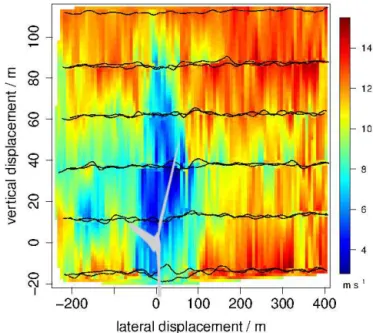
4.3 Measurements in the wake of a wind turbine
As shown in Fig. 5, MASC is able to fly safely in the wake of a 2.4 MW WEC. At the test site in Grevesmühlen, measure-ment flights were performed in the wake with flight legs in six distinct heights from just below the hub of the turbine at 75 m, up to 225 m. The flight legs are oriented perpendicular to the main wind direction. The resulting wind measurements presented in Fig. 7 show a picture of the shape and intensity of the wake in a distance of four rotor diameters behind the WEC. For better visualization, the linear interpolation tech-nique after Akima (1978) was applied between the measure-ments of the single flight legs at different altitudes, while the original flight leg paths are still depicted with black lines. Since the flight legs are not performed in parallel at the same time, the shape of the wake is somewhat distorted. Two flight legs at each altitude are used to average the results. The wind
speed drops from about 12 m s−1in the free stream to about
5–6 m s−1 in the wake of the turbine. This is a wind speed
0 100 200 300 400 500 600
−10
−5
0
5
10
flight leg distance / m
course de
viation / m
σ = 1.74 m
(a)
0 100 200 300 400 500 600
−10
−5
0
5
10
flight leg distance / m
course de
viation / m
σ = 5.99 m
(b)
0 100 200 300 400 500 600
−4
−2
0
2
4
flight leg distance / m
altitude de
viation / m
σ = 1.07 m
(c)
0 100 200 300 400 500 600
−4
−2
0
2
4
flight leg distance / m
altitude de
viation / m
σ = 1.5 m
(d)
0 100 200 300 400 500 600
−4
−2
0
2
4
flight leg distance / m
airspeed de
viation / m
s
−
1
σ = 0.48 m s−1
(e)
0 100 200 300 400 500 600
−4
−2
0
2
4
flight leg distance / m
airspeed de
viation / m
s
−
1
σ = 0.79 m s−1
(f)
Figure 5.Performance of MASC with ROCS autopilot in undisturbed atmosphere(a),(c),(e)and behind a wind turbine(b),(d),(f). All data were measured during the same flight (see green track in Fig. 3). The figures show three successive, individual flight legs at 100 m altitude (= hub height). Offsets between demanded values for course, altitude and airspeed were subtracted and can be higher than the standard deviationsσ. An average wind speed of 7 m s−1perpendicular to the flight path was present throughout the flight.
the turbine. These values are in agreement with lidar mea-surements performed by Iungo et al. (2013) or Käsler et al. (2009) for similar sized turbines and wind speeds.
4.4 Turbulence characteristics in a wind park
Turbulence has a high impact on efficiency of a wind turbine and also on the fatigue of rotors. However, a quantitative de-scription of the effects of turbulence is difficult and not yet available. MASC with its instrumentation for small scale tur-bulence measurement can deliver valuable data for studies
towards a deeper insight into the effects of turbulence on the turbines. Figure 8 shows measurements of turbulent kinetic energy (TKE) upstream and downstream a wind turbine cal-culated from wind measurements of MASC according to:
TKE=1
2
σu2+σv2+σw2
(1)
with standard deviationsσof the wind-vector componentsu,
vandwfor 700 m long flight legs. As expected, an increased
05
10
15
time / UTC
wind speed / m
s
−
1
14:26 14:31 14:36 14:41 14:46
lidar nacelle lidar ground tower masc
Figure 6. Comparison of horizontal wind speed in the main wind direction measured by tower wind sonic, nacelle-based lidar, ground-based lidar and MASC on 22 October 2013. For the nacelle based lidar, a measuring point 80 m in front of the nacelle was cho-sen, for the ground based lidar a measurement point at hub height close to the tower was selected.
Figure 7.Wind speed measurement from RPA MASC in the wake of a K110 WEC. Flight legs (black lines) are performed perpendic-ular to the main wind direction, four rotor diameters downstream of the WEC, in six distinct altitudes. Linear interpolation was applied between the wind speed measurement of the single legs and visual-ized with a colour scale. The position of the WEC is illustrated by the gray shade.
−600 −400 −200 0 200 400 600
05
0
100
150
200
250
300
Turbulent kinetic energy
Distance to wind turbine / m
agl / m
wind
1m2s−2 5 m2s−2
Figure 8.Turbulent kinetic energy measured in flight legs behind a WEC (green line) in different distances and in comparison to up-stream turbulence. Each circle represents one single flight leg.
In this case it also appears that a higher degree of turbulence is present upstream, very close to the wind turbine.
5 Conclusions
Remotely Piloted Aircraft of type MASC with an instrumen-tation that allows vertical soundings of the atmosphere as well as in-situ turbulence measurement are not only a valu-able tool for fundamental boundary layer research, but can be directly applied for wind energy research. Even in high wind speeds, the RPA MASC is able to operate safely, also in the wake of large WEC. Its flexible operation in almost any lo-cation and low operating cost makes it superior to stationary measurement equipment like towers and lidars for short, fo-cussed experiments. It is shown how the data collected by MASC can provide information about inflow conditions, the wake structure of a WEC and the turbulence of the inflow and wake of the turbine. In the project “Lidar Complex”, MASC is first used extensively in wind energy research.
Acknowledgements. We are much obliged to the referees for their detailed review of this paper. The Project “Lidar complex” is funded by the German Federal Ministry for the Environment, Nature Conservation and Nuclear Safety (BMU) on the basis of a resolution of the German Bundestag. The MASC airframe was build by “ROKE-Modelle”. We like to thank our safety pilots Maximilian Ehrle and Markus Auer for the perfect job in the measurement campaigns. We acknowledge support by Deutsche Forschungsgemeinschaft and Open Access Publishing Fund of Tuebingen University.
Edited by: S.-E. Gryning
References
Akima, H.: A Method of Bivariate Interpolation and Smooth Sur-face Fitting for Irregularly Distributed Data Points, ACM Trans. Math. Softw., 4, 148–159, doi:10.1145/355780.355786, 1978. Bonin, T., Chilson, P., Zielke, B., and Fedorovich, E.: Observations
of the Early Evening Boundary-Layer Transition Using a Small Unmanned Aerial System, Bound.-Layer Meteorol., 146, 119– 132, doi:10.1007/s10546-012-9760-3, 2013.
Iungo, G. V., Wu, Y.-T., and Porté-Agel, F.: Field Measurements of Wind Turbine Wakes with Lidars, J. Atmos. Oceanic Technol., 30, 274–287, doi:10.1175/JTECH-D-12-00051.1, 2013. Käsler, Y., Rahm, S., Simmet, R., and Trujillo, J. J.: Wake
mea-surements of a multi-MW wind turbine with long range lidar, in: Euromech Colloquium 508 on wind turbine wakes, European Mechanics Society, Madrid, Spain, 2009.
Martin, S. and Bange, J.: The Influence of Aircraft Speed Variations on Sensible Heat-Flux Measurements by Differ-ent Airborne Systems, Bound.-Layer Meteorol., 150, 153–166, doi:10.1007/s10546-013-9853-7, 2014.
Martin, S., Bange, J., and Beyrich, F.: Meteorological profiling of the lower troposphere using the research UAV “M2AV Carolo”, Atmos. Meas. Tech., 4, 705–716, doi:10.5194/amt-4-705-2011, 2011.
Martin, S., Beyrich, F., and Bange, J.: Observing Entrain-ment Processes Using a Small Unmanned Aerial Vehicle: A Feasibility Study, Bound.-Layer Meteorol., 150, 449–467, doi:10.1007/s10546-013-9880-4, 2014.
Peña, A., Hasager, C., Lange, J., Anger, J., Badger, M., Bingöl, F., Bischoff, O., Cariou, J.-P., Dunne, F., Emeis, S., Harris, M., Hof-säss, M., Karagali, I., Laks, J., Larsen, S., Mann, J., Mikkelsen, T., Pao, L., Pitter, M., Rettenmeier, A., Sathe, A., Scanzani, F., Schlipf, D., Simley, E., Slinger, C., Wagner, R., and Würth, I.: Remote Sensing for Wind Energy, DTU Wind Energy E, DTU Wind Energy, 2013.
Rettenmeier, A., Hofsäß, M., Schlipf, D., Trujillo, J. J., Siegmeier, B., and Kühn, M.: Wind field analyses using a nacelle – based LIDAR system, in: European Wind Energy Conference, Warsaw, Poland, 2010.
Reuder, J. and Jonassen, M. O.: First Results of Turbulence Mea-surements in a Wind Park with the Small Unmanned Meteoro-logical Observer {SUMO}, in: Selected papers from Deep Sea Offshore Wind Ramp Conference, Vol. 24, 176–185, Trondheim, NO, doi:10.1016/j.egypro.2012.06.099, 2012.
Reuder, J., Brisset, P., Jonassen, M., Müller, M., and Mayer, S.: The Small Unmanned Meteorological Observer SUMO: A new tool for atmospheric boundary layer research, Meteorol. Z., 18, 141– 147, 2009.
Spieß, T., Bange, J., Buschmann, M., and Vörsmann, P.: First Ap-plication of the Meteorological Mini-UAV “M2AV”, Meteorol. Z. N. F., 16, 159–169, 2007.
Subramanian, B., Chokani, N., and Abhari, R. S.: Full Scale HAWT: Structure of Near Wake Turbulence Measured with Instrumented UAV, in: EWEA 2012 Conference Proceedings, Copenhagen, DK, 2012.
Thomas, R. M., Lehmann, K., Nguyen, H., Jackson, D. L., Wolfe, D., and Ramanathan, V.: Measurement of turbulent water va-por fluxes using a lightweight unmanned aerial vehicle system, Atmos. Meas. Tech., 5, 243–257, doi:10.5194/amt-5-243-2012, 2012.
van den Kroonenberg, A. C., Martin, T., Buschmann, M., Bange, J., and Vörsmann, P.: Measuring the Wind Vector Using the Au-tonomous Mini Aerial Vehicle M2AV, J. Atmos. Oceanic Tech-nol., 25, 1969–1982, 2008.
Wildmann, N., Mauz, M., and Bange, J.: Two fast temperature sen-sors for probing of the atmospheric boundary layer using small remotely piloted aircraft (RPA), Atmos. Meas. Tech., 6, 2101– 2113, doi:10.5194/amt-6-2101-2013, 2013.
Wildmann, N., Ravi, S., and Bange, J.: Towards higher accuracy and better frequency response with standard multi-hole probes in tur-bulence measurement with remotely piloted aircraft (RPA), At-mos. Meas. Tech., 7, 1027–1041, doi:10.5194/amt-7-1027-2014, 2014.
Wu, Y.-T. and Porté-Agel, F.: Large-Eddy Simulation of Wind-Turbine Wakes: Evaluation of Wind-Turbine Parametrisations, Bound.-Layer Meteorol., 138, 345–366, doi:10.1007/s10546-010-9569-x, 2011.
Wu, Y.-T. and Porté-Agel, F.: Atmospheric Turbulence Effects on Wind-Turbine Wakes: An LES Study, Energies, 5, 5340–5362, doi:10.3390/en5125340, 2012.