Set-Point Manipulation Approach toward
Overcoming Limitation of Closed Architectural
Framework
Tan Kok Kiong and Kyaw Ko Ko Htet
Abstract—In this paper, a set-point manipulation approach towards achieving control adaptation in a closed architectural control framework is proposed and designed. The approach is designed to allow the flexibility to incorporate control adapta-tion which is not easily accomplished with a built-in proprietary controller, such as an appropriate anti integral windup measure (AIWM). The approach is amenable to closed systems without the need to replace the built-in controller. The realization of the proposed configuration will be illustrated with respect to a PID controller although the framework proposed is general allowing the use of higher order controller too. Simulation examples and experimental results on the speed control of an electric vehicle will be duly furnished to show the motivation for such an approach and the improved performance achievable with closed-architectural systems.
Index Terms—PID, Closed-Architecture controller, Set-Point Manipulation, Integral Windup.
I. INTRODUCTION
P
ROPORTIONAL-Integral-Derivative (PID) control is generally a popular form of control for applications with modest control specifications and they can be found in a wide and diverse range of applications such as but not limited to process control, automotive, flight control and factory automation. PID controllers can be combined with logic, sequential machines, selectors, and function blocks to build complicated automation systems such as those used for energy production, transportation, and manufacturing. On top of that, many sophisticated control strategies, such as model predictive control, are also organized hierarchically based on PID control. The main reason for its success is that it has a simple structure which is easy to be understood by the engineers and under practical conditions, it has been performing more reliably compared to other advanced and complex controllers. It has remained true that PID controllers are by far the most dominating form of controllers in use today comprising more than 90% of industrial controllers.Driven by its popularity, PID control has been a de-facto industrial standard and automation equipment and instruments are often provided together with built-in PID control in proprietary and closed architectural forms so that the users and customers do not have to deal with them separately. These built-in solutions will typically restrict the
Manuscript received November 08, 2013; revised December, 2013. This work was supported in part by Economic Development Board of Singapore and National Instrument Singapore (Pte) Ltd.
K. K. Tan is with the Department of Electrical and Computer Engineering, National University of Singapore, 21 Lower Kent Ridge Road, Singapore 119077. E-mail: [email protected]
K. K. K. Htet is with the Department of Electrical and Computer Engineering, National University of Singapore, 21 Lower Kent Ridge Road, Singapore 119077. Email: [email protected]
users to input fixed control gains and the reference signal. Unfortunately, such a bundled solution poses serious con-straints when there arises needs to incorporate modifications and adaptation in the controller in situations when simply tuning the control gains in the closed system cannot achieve the performance needed. Two examples of such scenarios arising would be the need to bundle a suitable anti-windup mechanism for the integral control action and the flexibility to adapt control gains on the fly when faced with nonlinear or time varying processes. These scenarios are cumbersome to handle in a closed-architectural proprietary setup with-out tearing apart the overall system to retrofit an alternate controller and separate instrument to allow such flexibilities, incurring cost, time and a possible void of warranty on the equipment since that will be counter acting the intention of the manufacturer.
Integral windup commonly occurs due to control input limitation and saturation nonlinearity of the physical systems. When windup steps in, the performance of the closed-loop system significantly deteriorates yielding a larger overshoot, slower settling time and lower stability [1][2][3][4]. Thus, anti-integral-windup mechanisms (AIWM) are necessary to counter this phenomenon. Built-in PID controllers may or may not have an AIWM provided. When the built-in control is not equipped with an AIWM, anti-windup can be mediated with a low integral control gain. Even if it is equipped with AIWM, there are different types of AIWMs and each strives in a specific situation. Thus, the AIWM provided may not be suitable for the actual application and changes to the AIWM configuration parameters have to be done continuously to retain it, or an alternate one has to be employed. These are not easily done with a closed framework.
put signals is used to generate a feedback signal to moderate the integrator’s output. In limited integrator schemes [13], the integrator value is limited with a high-gain dead zone to ensure operation in the linear range.
Limited integrator schemes are not commonly used es-pecially in built-in controllers as they are not amenable to general usage [14]. Back tracking calculation and especially conditional integration schemes are more commonly found in these built-in controllers. But even under the commonly used conditional integration schemes, there are four main types.
1) Type A: the integral term is limited to a predefined value.
2) Type B: The integration is stopped when the error is greater than a predefined threshold, when the process variable is too far from the set-point.
3) Type C: The integration is stopped when the control variable saturates.
4) Type D: The integration is stopped when the control variable saturates and the control error and the control variable have the same sign.
Type A requires a predefined cut-off and Type B requires a predefined threshold to be configured for proper implementa-tion of the control applicaimplementa-tion. The limitaimplementa-tion of the integral term in Type A can prevent the control from attaining set-point tracking. Likewise, the predefined threshold in Type B may cause the control to be trapped in an unreachable state wherein the control error remains above the threshold. In other words, setting the above two parameters too high allows significant build-up of the integral windup and setting them too low will prevent the integral from correcting the steady stage error. Thus, these parameters should be set just enough so that the integral is able to correct the steady stage error, which is highly dependent on the process static gain. As a result, in order to achieve the optimal anti integral windup measure with Types A and B, these parameters should be set accurately according to the process static gain. In a nonlinear process wherein the DC gain is varying, these pre-set values do not match the actual gains and thus, the closed loop systems with Types A and B can result in a steady-state error [14].
The issues relating to steady-state error with Types A and B above can be avoided by using Type C or D. Comparing these two types, Type D offers the significant advantage that the integrator is not inhibited as it helps to push the control variable away from saturation. In cases when the process and the instrument are separate entities, these two types require the knowledge of the process saturation region in order to set a suitable value to the maximum instrument output parameter. However, when the process saturation region is varying and unpredictable, setting appropriate values for this parameter is often challenging. An inadequate parameter can
due to nonlinearities and disturbances occurring over time. As a result, parameters such as the predefined value, the threshold, and the maximum output allowable need to be updated continuously on the fly.
III. PROPOSEDCONFIGURATION ANDAPPROACH
Consider a general closed-loop control system in Fig. 1, using a built-in controller GC = GC1GC2 (shown in the dotted box) to control the process GP. r, w, y represent the set-point, disturbance and process variable respectively. Modern devices may even bundle the controller GC and processGP as a single entity. The controller will typically receive as user inputs the set-pointrand a set of fixed control gains.
The closed-loop transfer function betweenyandris given by
Gyr=
GC1GC2GP
1 +GC1GC2GP
, (1) and the closed-loop transfer function between y and w is
Gyw=1+GGCPGP
Now consider the proposed control configuration to allow control adaptation in the closed architectural control system as shown in Fig. 2.
The part of the controller in the dotted box can be thought as a set-point manipulator transforming the original set-point
r into a new one r¯ for the controller GC1 which directly manipulates the process. The closed-loop transfer functions betweeny and inputsr,wcan be shown to be
Gyr=
GC1GP( ¯GC+ 1)
1 +GC1GP( ¯GC+ 1)
(2)
Gyw=
GP
1 +GCGP
(3)
Thus, it can be observed that the proposed control con-figuration in Fig. 2 is equivalent to the closed-architectural control of Fig. 1 in terms of the closed-loop relationships if
¯
GC=GC2−1 (4) This implies that under the proposed configuration, a part or the full (GC2 = GC and GC1 = 1) built-in controller
GC can be realized outside of the built-in control system,
Fig. 2. Block Diagram of Proposed Control Configuration
thus enabling the flexibility for control adaptation including but not limited to the implementation of AIWMs and gain scheduling schemes.
Consider a PID realization of the proposed configuration where the built-in controller GC is a PID controller. Differ-ent variants of PID realizations can be possible under the proposed configuration. For example, PD control GC1 =
KC1(1 +Kds)can be retained in the built-in control and PI control GC2 =KC2(1 +Ksi)shifted outside of the built-in loop. If the full proportional gain is retained in the built-in control, i.e., KC2 = 1, then G¯C = Ksi . A pure integral control can be realized outside of the built-in control loop and equivalent set-point tracking and load disturbance attenuation is still achieved.
Alternatively, with GC1 = KC1 and GC2 = KC2(1 + Ki
s )(1 +Kds), the full PID control can be shifted outside of the built-in loop and only a proportional gain is applied for stabilization of the built-in control loop.
Remarks:
1) The integrator part of the control can be realized outside of the main control loop along with an appropriate AIWM. This allows an AIWM to be efficiently applied to the existing built-in control without one or an appropriate AIWM to replace an inappropriate built-in AIWM.
2) A gain scheduling strategy can be effectively realized with PID gains varying with respect to operating point or with time. This is achieved within the set-point manipulator. 3) A high order controller or a signal processing filter can be achieved with the built-in PID control, with the additional order of control incorporated intoGC2.
IV. INCORPORATINGAIWMINTOPROPOSED
CONFIGURATION
In this section, the approach to incorporate a suitable AIWM into a closed-architectural PID control system either without one or with an inadequate AIWM will be elaborated. Without loss of generality, we will use proportional control in the built-in controller, i.e., GC1 =KP . The saturation condition is thus given by:
u= ¯e.KP > umax or u= ¯e.KP < umin (5) where e¯ = y −¯r , and umax and umin are the higher and lower saturation limits of the input to the process respectively. We will elaborate the implementations of the Type C AIWM and the back tracking AIWM as examples in the following subsections. Simulation will be carried out in Section (V) to show that these approaches to implement
Fig. 4. Back Tracking AIWM with PI Control
AIWM achieve the same results as though the AIWM is incorporated into the built-in controller.
A. Implementation of Type C AIWM
The conditional function of the Type C is given by
e=
r−y ifδ <e < σ¯
0 otherwise (6)
wheree¯=y−r¯,σ= umax
KP andδ=
umin
KP .
The implementation of the Type C AIWM in the proposed configuration is shown in Fig. 3.
B. Implementation of Back Tracking AIWM
The typical implementation of a back tracking AIWM in a PI controller is shown in Fig. 4 [14] [15].
With the proposed configuration, the back tracking AIWM can also be realized outside of the P-only control loop as shown in Fig. 5.
V. SIMULATIONRESULTS
Fig. 3. Implementation of Type C AIWM in the Proposed Configuration
Fig. 5. Implementation of back tracking AIWM in the Proposed Configuration
A. Performance of Type C AIWM in the Proposed Configu-ration
The simulation is based on the process being a first order process with time delay given by:
GP =
0.5
s+ 1.5e
−0.1s (7)
Saturation limits of saturation of±10are simulated for the control variable. A disturbancew= 0.2is also introduced at some point into the simulation to show the disturbance re-jection performance. The built-in controller is a PI controller withKP = 20andKi= 3.
Type C AIWM of Fig. 3 is incorporated and simulated. The set-point tracking and load disturbance rejection per-formance is shown in Fig. 6 against the perper-formance from the built-in PI control without AIWM but with the same PI control gains. The improved performance is clearly evident with the AIWM incorporated. The same AIWM is also sim-ulated in the built-in controller and an identical performance is verified via simulation as also seen in Fig. 6.
B. Performance of Back Tracking AIWM in the Proposed Configuration
The same process and limits as in section (V-A) are used in this simulation. Back tracking AIWM of Fig. 5 is incorporated and simulated. The set-point tracking and load disturbance rejection performance is shown in Fig. 7 against the performance from the built-in PI control without AIWM but with the same PI control gains. The improved performance is clearly evident with the AIWM incorporated. The same AIWM is also simulated in the built-in controller
Fig. 6. Performance of Type C AIWM
and an identical performance is verified via simulation as also seen in Fig. 7.
These simulation examples highlight the equivalence in performance with the AIWM incorporated in the set-point manipulator and the improved performance achieved over a built-in controller without an AIWM.
VI. EXPERIMENTALVERIFICATION
Fig. 7. Performance of Back Tracking AIWM
Fig. 8. Single Seater MEV
Fig. 9. Built-in Control with Type A AIWM Provided
a Type A AIWM as shown in Fig. 9. The saturation function acts on the PID control signal to limit it to the specifications of the motor drives. The MEV uses two drive motors which are mounted at the rear wheels and these are integrated with an embedded PID controller which can accept only input of fixed control gains as well as the reference speed signal through the Controller Area Network (CAN) bus from the Main CPU of the EV as shown in Fig. 10. The drive motor assembly is shown in Fig. 11. The MEV represents a typical real example of an AIWM provided in the built-in control system.
The static gain of the speed-input relationship of the motor was calibrated by evaluating the steady state offset of the
Fig. 10. Hardware Block Diagram of the Drive Motor Control System
Fig. 11. Hardware Picture of Drive Motor Assembly
TABLE I ANEXAMPLE OF ATABLE
Surface Gain Similarity to gain on flat surface
Flat 0.063 100%
Up Slope ( 20 Degree) 0.098 156% Down Slope ( 20 Degree) 0.019 30%
speed control with a proportional only controller. Table I shows the variation in the gain with different slopes of the road. It can be observed that the variation in the static gain is significant. Thus, the Type A AIWM is not ideally suited for the speed control of the MEV.
A set of PI gains (i.e., KP = 0.6 and Ki = 0.02) was determined in a rigorous tuning session for the built-in control to work the best it could over different profiles of the road. The MEV was driven over a stretch of road with flat, up slope and down slope profiles at a constant target speed of 5km.h−1. The speed recorded over this travel is shown in Fig. 12. The passenger seated in the MEV can clearly experience the jerky movements due to fluctuations in the velocity of the MEV.
Fig. 12. Speed of the MEV with the built-in PI controller
Fig. 13. Block Diagram of the Improved Speed Controller
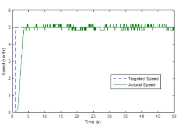
Fig. 14. Speed of the MEV with the proposed control and AIWM
capture the speed variation with the alternate AIWM. The clearly improved results are shown in Fig. 14.
As seen in Fig. 14, the amount of oscillation is signifi-cantly reduced from a RMS value of 0.20 to 0.11 resulting in a clearly smoother driving experience to the passenger. This improvement is achieved with no physical alteration done to the built-in controllers integrated to the motor drives.
VII. CONCLUSION
In this paper, a set-point manipulation approach towards achieving control adaptation in a closed architectural control framework is proposed and designed. Such an approach allows the flexibility to incorporate an appropriate AIWM and enabling adaptive control which cannot be achieved ef-fectively with a built-in proprietary controller. The approach can be adopted without having to remove or decommission the built-in controller. While the realization of the proposed configuration is with respect to a PID controller, the frame-work proposed is general allowing the use of higher order
the set-point manipulator which resides outside of the closed system.
REFERENCES
[1] K. J. Astrom, “Pid controllers: theory, design and tuning,”Instrument Society of America, 1995.
[2] S. Tarbouriech and M. Turner, “Anti-windup design: an overview of some recent advances and open problems,” Control Theory & Applications, IET, vol. 3, no. 1, pp. 1–19, 2009.
[3] B. Bahrani, S. Kenzelmann, and A. Rufer, “Multivariable-pi-based dq current control of voltage source converters with superior axis decoupling capability,”IEEE Transactions on Industrial Electronics, vol. 58, no. 7, pp. 3016–3026, 2011.
[4] R.-J. Wai, J.-D. Lee, and K.-L. Chuang, “Real-time pid control strategy for maglev transportation system via particle swarm optimization,” Industrial Electronics, IEEE Transactions on, vol. 58, no. 2, pp. 629– 646, 2011.
[5] H.-B. Shin and J.-G. Park, “Anti-windup pid controller with integral state predictor for variable-speed motor drives,”Industrial Electronics, IEEE Transactions on, vol. 59, no. 3, pp. 1509–1516, 2012. [6] J.-W. Choi and S.-C. Lee, “Antiwindup strategy for pi-type speed
controller,” Industrial Electronics, IEEE Transactions on, vol. 56, no. 6, pp. 2039–2046, 2009.
[7] J.-K. Seok, K.-T. Kim, and D.-C. Lee, “Automatic mode switching of p/pi speed control for industry servo drives using online spectrum anal-ysis of torque command,”Industrial Electronics, IEEE Transactions on, vol. 54, no. 5, pp. 2642–2647, 2007.
[8] J.-K. Seok, “Frequency-spectrum-based antiwindup compensator for pi-controlled systems,”Industrial Electronics, IEEE Transactions on, vol. 53, no. 6, pp. 1781–1790, 2006.
[9] K. Ohishi, E. Hayasaka, T. Nagano, M. Harakawa, and T. Kanmachi, “High-performance speed servo system considering voltage saturation of a vector-controlled induction motor,”Industrial Electronics, IEEE Transactions on, vol. 53, no. 3, pp. 795–802, 2006.
[10] R. Hanus, M. Kinnaert, and J.-L. Henrotte, “Conditioning technique, a general anti-windup and bumpless transfer method,” Automatica, vol. 23, no. 6, pp. 729–739, 1987.
[11] Y. Peng, D. Vrancic, and R. Hanus, “Anti-windup, bumpless, and conditioned transfer techniques for pid controllers,”Control Systems, IEEE, vol. 16, no. 4, pp. 48–57, 1996.
[12] K. Walgama, S. Ronnback, and J. Sternby, “Generalisation of condi-tioning technique for anti-windup compensators,” inControl Theory and Applications, IEE Proceedings D, vol. 139, no. 2. IET, 1992, pp. 109–118.
[13] N. J. KRIKELIS, “State feedback integral control with intelligentinte-grators,”International Journal of Control, vol. 32, no. 3, pp. 465–473, 1980.
[14] A. Visioli,Practical PID control. Springer, 2006.