JÚLIO CÉSAR TORRES RIBEIRO
SMELT SPOUT CORROSION IN A RECOVERY BOILER
VIÇOSA
MINAS GERAIS - BRASIL 2010
SMELT SPOUT CORROSION IN A RECOVERY BOILER
APROVADA: 14 de Junho de 2010.
_____________________________ Prof. Jorge Luiz Colodette
(Co-Orientador)
_____________________________ Profa. Vanessa de Freitas Cunha Lins
______________________________ Prof. Marcelo Cardoso
(Orientador)
AGRADECIMENTOS
A Deus, acima de tudo, e aos meus PAIS pelo amor, compreensão e apoio em todos os dias de minha vida.
À minha esposa Fabrícia e aos meus filhos Diego e Sara, pelo constante apoio e compreensão nesta jornada, inclusive nos finais de semana e noites de estudo em frente ao computador.
Aos professores Honghi Tran e Thomas Grace, da Universidade de Toronto, pelo apoio na revisão do texto e valiosa contribuição técnica.
Aos professores da Universidade Federal de Viçosa que com sua conduta séria souberam conduzir o curso de maneira constante, atenciosa e incentivadora. Em especial aos Professores Marcelo Cardoso, Jorge Luiz Colodette e Cláudio Mudado Silva pelo apoio e orientação na elaboração deste trabalho.
A CENIBRA pela oportunidade única de participação neste curso.
Ao Departamento de Recursos Humanos da CENIBRA, em especial a Srta Mônica, que não mediu esforços para que a CENIBRA participasse da 1ª Turma de Mestrado Profissional em Tecnologia de Celulose da Universidade Federal de Viçosa.
A todos os colegas de curso e empresa, que de uma forma ou outra apoiaram todo o
processo.
BIOGRAFIA
Júlio César Tôrres Ribeiro, filho de Pedro Américo Ribeiro e Juracy Tôrres Ribeiro, nasceu aos 5 dias de novembro de 1969, na cidade de Belo Horizonte, Minas Gerais.
Concluiu o segundo grau científico em 1987 no Colégio Municipal Marconi, em Belo Horizonte, MG.
Cursou Engenharia Mecânica no período de 1988 a 1992 pela Universidade Federal de Minas Gerais.
Em fevereiro de 1993 iniciou suas atividades profissionais na setor de celulose e papel como engenheiro trainee da Celulose Nipo-Brasileira S/A - CENIBRA, onde atualmente ocupa o cargo de coordenador de recuperação e utilidades.
Cursou MBA em gestão empresarial no período de 1998 a 2000 no programa de pós-graduação da FIA-USP, na cidade de São Paulo, SP.
Cursou pós-graduação lato sensu em Tecnologia de Celulose e Papel no período de fevereiro de 2001 a fevereiro de 2003 pela Universidade Federal de Viçosa.
Atua como membro do Sub-comitê de Segurança em Combustão do Comitê Brasileiro de Segurança em Caldeiras de Recuperação, CSCRB, desde 2002.
No período de 2004 a 2006 atuou como vice-coordenador da Comissão de
Recuperação e Energia da ABTCP e como coordenador no ano de 2007.
SUMÁRIO
RESUMO ... v
ABSTRACT ... vi
1- INTRODUÇÃO GERAL ... 1
2- ARTIGO : SMELT SPOUT CORROSION IN A RECOVERY BOILER ... 4
3- CONCLUSÕES GERAIS ... 22
BIBLIOGRAFIA ... 23
RESUMO
RIBEIRO, Júlio César Tôrres, M.Sc., Universidade Federal de Viçosa, Junho de 2010. Smelt spout corrosion in a recovery boiler. Orientador: Marcelo Cardoso. Co-orientadores: Jorge Luiz Colodette e Cláudio Mudado Silva.
Acidentes com Bicas de Smelt são reportados pelo Black Liquor Recovery Boiler Advisory Committee, BLRBAC, e constituem uma preocupação real de segurança sob o ponto
de vista operacional. Tipicamente o smelt escorre através de bicas refrigeradas a água da
fornalha para o tanque dissolvedor e uma falha pode levar a explosões pelo contato água-smelt. Este trabalho estuda um caso real onde condições severas de corrosão culminaram com
ABSTRACT
RIBEIRO, Júlio César Tôrres, M.Sc., Universidade Federal de Viçosa, Junho de 2010. Smelt spout corrosion in a recovery boiler. Advisor: Marcelo Cardoso. Co-advisors: Jorge Luiz Colodette and Cláudio Mudado Silva.
Smelt Spout accidents are reported by Black Liquor Recovery Boiler Advisory Committee, BLRBAC, and constitute a real safety concern from the operational point of view. Typically smelt flows through water cooled spouts from furnace to the smelt dissolving tank and a failure can lead to smelt-water contact explosions. This work studies a real case where severe corrosion led to an in-service failure of one of the six spouts on a recovery boiler at Cenibra. The failure resulted in a large amount of cooling water entering the boiler and contacting smelt around the spout opening, but fortunately no smelt-water explosion occurred. An extensive investigation was conducted to determine the causes of the spout failure. It was concluded that the failure was caused by insufficient cooling water flow to the smelt spout, which, in turn, was caused by a sequence of events that occurred after a general black out of an electrical energy system at the mill. The experience has led to the development and placement of operating and maintenance procedures that ensure adequate cooling water flow
1- INTRODUÇÃO GERAL
De acordo com os dados da Associação Brasileira de Celulose e Papel - BRACELPA, o Brasil é o quarto produtor mundial de celulose do mundo desde 2008, com 12.697 mil tsa,
estando atrás apenas dos Estados Unidos, Canadá e China. No ano de 2009, um ano de intensa crise econômica, a produção cresceu 6% atingindo a marca de 13.461 mil tsa, enquanto em outros países de grande expressão ocorreram reduções de produção em função de demanda e custos de produção (BRACELPA, 2010a). Para os próximos anos espera-se incrementos de
produção cada vez maiores em função dos maciços investimentos em empreendimentos do setor.
Na mesma velocidade em que novos empreendimentos são postos em marcha cresce a contribuição do setor no superávit comercial brasileiro. De acordo com BRACELPA (2010a) as exportações de celulose contribuíram positivamente na balança comercial com US$ 3,643 Bilhões em 2008, resultado 30,5% superior ao atingido em 2007. Também, conforme esperado, o setor emprega grandes volumes de mão-de-obra, estimados em 114.000 empregos diretos e 500.000 indiretos (BRACELPA, 2010b).
A tecnologia de extração de celulose é muito bem estabelecida e dominada por fornecedores de equipamentos e produtores de celulose. Existem vários processos industriais de extração de celulose conforme o produto final desejado, porém o processo de produção mais amplamente utilizado no mundo é o processo Kraft, responsável por 67% da produção mundial de celulose (TRAN, 2010). Kraft é uma palavra de origem germânica que significa forte e foi utilizada para designar o processo em função da polpa de alta resistência produzida. O processo Kraft foi descoberto por Dahl, em 1879, porém a sua ampla utilização só foi possível após o desenvolvimento da caldeira de recuperação química por Tomlinson, na década de 1930 (TRAN, 2010). Além de sua versatilidade, caracterizada pelo grande número
de espécies de madeira que podem ser processadas, o processo Kraft possui um eficiente ciclo de recuperação de produtos químicos, responsável por níveis de recuperação de até 97% nas fábricas modernas. Considera-se que a viabilidade econômica e ambiental de uma fábrica de celulose é sustentada pelo ciclo de recuperação química, na medida em que elevada carga orgânica, originada do cozimento da madeira, é incinerada na caldeira de recuperação. Este processo fornece, em casos específicos, até mais de 100% das demandas de energias térmica e elétrica necessárias ao pleno funcionamento da unidade industrial.
passou por muitos aperfeiçoamentos desde o seu surgimento na década de 30, porém a
essência do processo de combustão permanece a mesma. O processo de combustão do licor se dá em um leito de fundidos, no fundo da fornalha, composto essencialmente de sais de sódio e enxofre e carbono. A massa de fundido, também denominado smelt, em função das reações químicas envolvidas, é naturalmente mantida entre 750 e 850ºC e é removida de dentro da fornalha através de seu escoamento pelas bicas de fundido, ou, como mais comumente denominadas, bicas de smelt. Usualmente as bicas de smelt possuem um sistema de refrigeração a água, podendo este ser pressurizado ou à vácuo, que é responsável por manter a sua integridade em operação.
A possibilidade de contato água-smelt é uma das grandes preocupações na operação de uma caldeira de recuperação. Apesar dos rígidos controles de fabricação, instalação e operação, sempre existe a possibilidade de um vazamento de água no sistema de refrigeração. Devido à grande energia concentrada na massa de fundido, o contato água-smelt normalmente é catastrófico e responsável pela grande maioria das explosões em caldeiras de recuperação. Baseado na estatística consolidada pelo BLRBAC (2009b) verifica-se que no período de 1980 a 2009 ocorreram 31 explosões em caldeiras de recuperação nos Estados Unidos, sendo que 21 causadas pelo contato água-smelt. Em outra avaliação, realizada por Grace (2010),
verifica-se que de um total de 28 explosões de caldeiras de recuperação por contato água-smelt, cinco ocorreram devido a vazamentos em bicas, sendo três de moderada a elevada
magnitude.
A operação segura das caldeiras de recuperação sempre foi um tema muito discutido e estudado nos países onde a indústria de celulose e papel se instalou ao longo dos anos. Em um passado remoto, muitas mortes ocorreram em função de explosões em caldeiras de recuperação causadas por falhas operacionais, de projeto e/ou de materiais. A criação de comitês de segurança, compostos por profissionais da indústria, foi uma das maneiras encontradas para se estudar os problemas e desenvolver mecanismos de prevenção à falhas. O trabalho destes comitês, dentre os quais destaca-se o Black Liquor Recovery Boiler Advisory Committee (BLRBAC), é caracterizado por intensa colaboração entre empresas, especialmente
-5 10 15 20 25 30 35 40
60´s 70´s 80´s 90´s 00´s
# o f E x p lo s io n s Decade Combustible Water-Smelt
Gráfico 1 - Estatística de explosões com caldeiras de recuperação nos EUA. Fonte: BLRBAC, 2009b.
Não obstante as questões de operação segura, a parada não programada de uma caldeira de recuperação devido a uma explosão pode significar a parada de toda a fábrica por vários dias ou até meses, além de demandar elevado capital na recuperação da capacidade produtiva da mesma. Tal situação pode chegar a comprometer a continuidade e saúde financeira de todo o empreendimento.
Este trabalho, baseado em uma situação real vivenciada em uma fábrica de celulose brasileira, tem por objetivo estudar o mecanismo de falha por corrosão a alta temperatura de uma bica de smelt em serviço. Trata-se de uma ocorrência rara e de grande complexidade, o
que pode ser comprovado pela quase total inexistência de literatura sobre o assunto. Uma das alternativas na condução do trabalho, especialmente devido à escassez de literatura, foi a consulta a metalurgistas e especialistas em corrosão.
Foi exatamente este caráter inédito da ocorrência, e de grande importância prática sob
SMELT SPOUT CORROSION IN A RECOVERY BOILER
Julio César Tôrres Ribeiro Celulose Nipo-Brasileira S.A. Belo Oriente, MG, BRAZIL
(Also with Universidade Federal de Viçosa, Viçosa, BRAZIL)
Marcelo Cardoso
Department of Chemical Engineering/School of Engineering Federal University of Minas Gerais (UFMG)
Belo Oriente, MG, BRAZIL
Honghi Tran Pulp & Paper Centre University of Toronto Toronto, ON, CANADA
ABSTRACT
Severe corrosion led to an in-service failure of one of the six spouts on a recovery boiler at Cenibra. The failure resulted in a large amount of cooling water entering the boiler and contacting smelt around the spout opening, but fortunately no smelt-water explosion occurred. An extensive investigation was conducted to determine the causes of the spout failure. It was concluded that the failure was caused by insufficient cooling water flow to the smelt spout, which, in turn, was caused by a sequence of events that occurred after a general black out of an electrical energy system at the mill. The experience has led to the development and placement of operating and maintenance procedures that ensure adequate cooling water flow to smelt spouts to prevent future failures.
INTRODUCTION
recovery boiler (RB) was built in 1976. It has a firing capacity of 1800 tonnes (t) of BL ds/day
but is presently in a standby condition. The #2 RB was built in 1992 and presently burns 2700 t BL ds/day at 72% solids. The #3 RB, the newest and largest of the three, started up in 2006 and burns 3500 t BL ds/day at the same solids. These boilers produce superheated steam rated at 65 bars and 450ºC, and they were all supplied by CBC, a Mitsubishi Heavy Industries branch in Brazil.
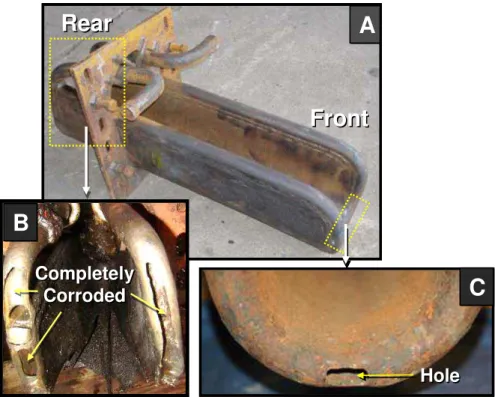
The mill electrical power is supplied by two turbo-generators, 40 and 60 MW, and by the grid, 9.5 MW. The generators operate in island mode and are not directly connected to the grid. The mill had never had an Emergency Shutdown Procedure (ESP) since its startup in 1976, until February 2008, when one of six smelt spouts of the #2 RB failed (Figure 1). This spout #5 was severely corroded that water was leaking out and so coming into contact with molten smelt. Figure 2 shows a large hole at the spout lip (front end) and multiple layers of large perforations along the inlet and outlet cooling water tubing on the furnace side (rear end) of the spout.
The ESP occurred seven days after a total mill-wide power failure that disrupted operations.
Although the incident did not lead to a smelt-water explosion fortunately, the severity of the problem and the potential damage it might have caused prompted the mill to conduct an extensive investigation to determine the causes of the spout failure. This investigation involved documentation of the sequence of events, analysis of relevant process data, non destructive testing of all smelt spouts and metallurgical analysis of corroded and non-corroded section of the failed spout. The paper discusses the smelt spout system, the key findings of the investigation, the connection between the power failure and the smelt spout leak, the underlying reasons the failure occurred and the steps taken to prevent a recurrence in the future.
SMELT SPOUT SYSTEM
The spouts were supplied by the same boiler manufacturer, CBC. They are made of carbon
steel with no weld overlay and inserted into the boiler (Figure 2A). All three recovery boilers use the same type and model of spouts which are essentially the same as the original design that was used in 1976. Over the years, the mill has been following BLRBAC operation procedures to discard all smelt spouts and replace them with a new set of spouts every year regardless of their condition [1]. They have always been found to be in good condition after one year in service with no excessive thinning or corrosion. This specific set of the #2 RB smelt spouts had been in service for ten months at the time of the incident.
6
4
2
3
1
5
Corroded Spout
6
4
2
3
1
2
3
4
5
6
1
5
Corroded Spout
Figure 1. Schematic drawing of the #2 recovery boiler and smelt spout identifications.
access. Monitoring through DCS the cooling water temperature discharging from each spout
with a thermoprobe was the primary means for verifying their proper operation.
Front
Front
Rear
Rear
Hole Hole Completely Corroded Completely CorrodedA
A
B
B
C
C
Front
Front
Rear
Rear
Hole Hole Completely Corroded Completely CorrodedA
A
B
B
C
C
Figure 2. Large perforations at the rear end and a hole at the front lip of the severely corroded Spout #5.
Recirculation Pumps
Head Tank
Collection Tank Spouts 1 2 3 4 5 6
Thermoprobes Hand Valve Recirculation Pumps Head Tank Head Tank Collection Tank Collection Tank Collection Tank Spouts 11 22 33 44 55 66
Thermoprobes Hand Valve
There is a hand valve (normally wide open) in the main cooling water line leaving the head
tank. This main line is divided into six smaller lines, one to each spout with a separate shutoff valve to isolate the cooling water to that spout in the event of a spout leak. Since the system at the time of the incident did not have the capability of adding firewater to the head tank in the event of a power failure, the loss of electrical power means that the recirculation pumps were unable to continue delivering water to the head tank, which would eventually run out of cooling water.
SEQUENCE OF EVENTS
February 11, 2008 (Black Out)
The #2 RB was operating normally that day until 9:02 PM when a general electrical power blackout occurred due to a short circuit in the turbo-generator #1. The short circuit caused most emergency systems to fail, including the grid power and backup diesel generators. The mill had no electrical power for 71 minutes. The power failure caused the boiler to trip, but smelt continued to flow out of the furnace for some time after the boiler trip.
The loss of power also caused both recirculation pumps to stop, thereby shutting off the return cooling water flow to the head tank. In order to preserve cooling water flow for a longer time during the black out, a boiler operator partially closed the hand valve on the main line from the head tank. He thought that he closed it halfway, but there is no way to tell if it was actually the case, since the hand valve had no marks to indicate the degree of closure. It was not known how much cooling water was flowing to each spout at that time, since there were no flowmeters and it was difficult to check visually.
0
20
40
60
80
100
Tempe
rat
u
re
(
oC
)
18:00 00:00 06:00 12:00 18:00 00:00 06:00 12:00 18:00
0
20
40
60
80
100
Amper
age
(A
)
Feb.11, 2008 Feb.12, 2008
Feb.10, 2008
Spouts #1, 2,3,4,5,6 and Tank
Spout #5 Spouts #1, 2,3,4,6
and Tank
Power Black Out
Pump #1 Pump #2
0
20
40
60
80
100
Tempe
rat
u
re
(
oC
)
18:00 00:00 06:00 12:00 18:00 00:00 06:00 12:00 18:00
0
20
40
60
80
100
0
20
40
60
80
100
Amper
age
(A
)
Feb.11, 2008 Feb.12, 2008
Feb.10, 2008
Spouts #1, 2,3,4,5,6 and Tank
Spout #5 Spouts #1, 2,3,4,6
and Tank
Power Black Out
Pump #1 Pump #2
Figure 4. Cooling water trend before and after the blackout period
February 16, 2008 (Boiler Startup)
The mill #1 production line was down for five days while the turbo-generator #1 was fixed. Only the #3 RB was operated during this period. The #2 RB was started up on February 16, 2008 at 3:10 AM and began burning black liquor at 9:40 AM. During this period, an unusually low and erratic cooling water temperature was noted on spout #5 as can be seen in Figure 5. This was the first time that the abnormal behaviour of spout #5 was noted on the DCS, even though it had occurred 5 days earlier. The boiler operator asked for maintenance and was told that the thermocouple in the thermoprobe was bad and needed to be replaced. The thermocouple was checked after the ESP and was found to be normal; no replacement was made.
February 18, 2008 (ESP)
stopped flowing. As he started cleaning the spout with a steel lance, thinking it was a common
jelly-roll smelt situation, he noted suddenly that water was flowing down the spout trough and that the bed was dark near the spout area. Thinking the water was from a leak on spout #5, the operator shut off the cooling water valve to stop the water flow to that spout. The water, however, kept flowing out from the furnace even after the valve had been closed. The operator then saw the water was sizzling and rumbling inside the furnace and it appeared to come from a primary air port tube nearby. He immediately called for an ESP, which was initiated at 3:29 AM on February 18, 2008.
The boiler was firing 1800 t BLds/d when ESP was initiated. The sequence of events shows that the boiler had been burning black liquor with spout #5 operated at an usually low cooling water temperature for nearly 2 days before the ESP.
0
20
40
60
80
100
Tempe
rat
u
re
(
oC
)
0
20
40
60
80
100
Amper
age
(A
)
Spouts #1, 2,3,4,6
Spout #5
Tank
Pumps #1 and 2
18:00 00:00 06:00 12:00 18:00 00:00 06:00 12:00 18:00 00:00 06:00 12:00 18:00 00:00 06:00 12:00 18:00
Feb.16 Feb.17
Feb.15 Feb.18 Feb.19, 2008
0
20
40
60
80
100
Tempe
rat
u
re
(
oC
)
0
20
40
60
80
100
0
20
40
60
80
100
Amper
age
(A
)
Spouts #1, 2,3,4,6
Spout #5
Tank
Pumps #1 and 2
18:00 00:00 06:00 12:00 18:00 00:00 06:00 12:00 18:00 00:00 06:00 12:00 18:00 00:00 06:00 12:00 18:00
18:00 00:00 06:00 12:00 18:00 00:00 06:00 12:00
18:00 00:00 06:00 12:00 18:00 00:00 06:00 12:00 18:0018:00 00:0000:00 06:0006:00 12:0012:00 18:0018:00 00:0000:00 06:0006:00 12:0012:00 18:00
Feb.16 Feb.17
Feb.15 Feb.16 Feb.17 Feb.18 Feb.19, 2008
Feb.15 Feb.18 Feb.19, 2008
Figure 5. Cooling water trends on restart of #2 recovery boiler
February 19, 2008 (Damage Inspection)
spout lip (Figure 6). From a mandoor one floor above the spout floor, a pool of water could be
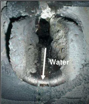
seen around spout #5 (Figure 7). A close look at the rear end of the spout revealed that the inlet and outlet of the cooling water tubing and the trough were completely corroded through, and some water still remained on the trough (Figures 7, 2B, and 8B).
Water
Water
Figure 6. Water running out of spout #5 from inside the furnace, 12 hours after ESP.
Water
Primary Air Ports
Primary Air Ports
Primary Air Ports
Smelt Bed
Smelt Bed
Smelt Bed
Water
Pool
Water
Water
Pool
Pool
Spout #5 Spout #5 Spout #5Water
Water
Primary Air Ports
Primary Air Ports
Primary Air Ports
Smelt Bed
Smelt Bed
Smelt Bed
Water
Pool
Water
Water
Pool
Pool
Spout #5 Spout #5 Spout #5THE INVESTIGATION
The investigation included a review of event chronology, operator interviews, trend analyses of the #2 RB and its spout cooling system operating data, operating procedures of emergency systems, and metallurgical evaluation of corroded and non corroded spouts. The main focus was on determining the causes of spout failure and devising operational and equipment modifications to avoid a repeat occurrence.
A thorough inspection was conducted on the spout cooling system, particularly the water lines shown in Figure 3. It was discovered during the inspection that the individual valve identifications were reversed between spouts #3 and #5, although the identification swap had probably been there since the boiler upgrade in 2004. This means that when the operator closed the water valve to spout #5 just before the ESP, he, in fact, shut off the cooling water to spout #3. This explains why water continued to enter the furnace through spout #5 even though the valve was closed. This also means that spout #3 passed through the ESP with no water cooling.
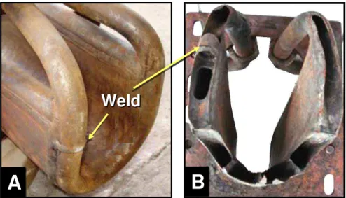
Non destructive dye-penetrant tests, thickness measurements and visual inspection were performed on all spouts and waterwall tubes near spout openings. The results showed that waterwall tubes were intact and that spout #1, 2, 3, 4 and 6 were in excellent condition with no signs of thinning, cracking or internal deposits. On spout #5, however, in addition to large perforations along the cooling water tubing at the rear end of the spout, there appeared to be a defect in the weld that joined the inlet cooling water tube and the outlet tube as can be seen on figures 8A and B.
A large section of spout #5 (corroded) and a section of spout #3 (not corroded) were also sent to an external laboratory, Nalco Company, in Naperville, IL, USA for metallurgical analysis.
B
B
Weld
Weld
A
A
B
B
Weld
Weld
A
A
Weld
Weld
A
A
Figure 8. (A) Weld connecting the cooling water tube to the spout at the rear end of a good spout. (B) Suspected “defect” on the weld joining the inlet and outlet cooling water tubes of spout #5
The metallurgical analysis by Nalco revealed that the metal loss of spout #5 was mainly from the external surface (Figure 9). In the areas of severe wastage and along the bottom of the trough, the metal surface was smooth with signs of gouging, resulting presumably from the erosion-corrosion action of molten smelt flowing over the spout surface (Figure 10). The analysis also revealed that the wastage on spout #5 was mainly on the furnace side where heat input is greatest, suggesting a strong temperature dependence of corrosion rates. The microstructure consisted of spheroidized carbides in a ferrite matrix (Figure 11), suggesting that the metal temperature must have exceeded 540oC (1000oF) for a period of time.
A
B
A
B
A
B
A
B
A
B
A
B
Flowing Smelt
Gouging
Figure 10. Smooth surface of spout #5 with signs of gouging by molten smelt.
10 m
10 m
10 m
Figure 11. Microstructure of the metal near the corroded area of spout #5
Some shallow depressions were also found along the bottom of some cooling water passages. The patterns, however, were characteristic of those caused by idle time oxygen pitting. This type of corrosion is generally superficial and is unlikely to be the contributing factor in the failure of spout #5.
spout #5. This implies that spout #3 did not experience significant overheating, despite the
fact that it had its cooling water flow cut off just before the ESP and would have been exposed to smelt flow for some time while the ESP was in effect.
Figure 12. Internal surface of Spout #3 (left) and Spout #5 (right)
INTERPRETATION OF RESULTS
Causes of Failure
It was apparent from the investigation that the failure of spout #5 was caused by excessive overheating of the spout metal surface and the subsequent aggressive attack by flowing smelt,
and that the loss of cooling water to that spout was the main reason for the overheating. Some of the overheating occurred during the black out period as indicated by the low cooling water temperature from spout #5 after the black out. Overheating also occurred after the boiler was restarted and was on liquor for nearly 2 days before the ESP. It is unclear, however, which period was more damaging to the spout: during the black out or during the startup after the ESP.
other spouts and the collection tank. While it is not known what caused the low cooling water
temperature of spout #5 during the power blackout, the data suggests that spout #5 did experience enough damage that it impaired the cooling water flow through that spout.
The suggested “defect” found in the weld of spout #5 (Figure 8) may play a role in its failure. It is possible that the sudden temperature change in the boiler due to power blackout may have caused the weld to fail, resulting in a small crack through which cooling water leaks out to the furnace. This, in turn, reduces the cooling water flow to the spout, causing it to overheat, and hence, to corrode. As the crack becomes larger, more water leaks out and less passes through the spout, aggravating the problem further.
The leaked water begins to accumulate in the furnace near the spout when there is more of it there than it can vaporize. It forms a pool of concentrated smelt solution (saturated green liquor) which pours out the boiler through the spout. This concentrated smelt solution can also be detrimental to the spout (carbon steel) for two main reasons: i) it contains corrosive Na2S2O3 as a result of partial oxidation of Na2S in the solution, and ii) it cannot vaporize easily due to boiling point rise and thus can remain as liquid at a temperature as high as 180oC
[3]. Some smelt solution entered the interior of spout #5 where it re-crystallized to form deposits, leading eventually to complete clogging of cooling water passes, as shown in Figure 13. Smelt Deposit Smelt Deposit Smelt Deposit Smelt Deposit
The clogging, in turn, impaired the cooling water flow, forcing it to partially by-pass the spout
and flow directly to the outlet tube. This could be one of the reasons for the lower cooling water temperature of spout #5 compared to other spouts. There are two other possible reasons for the low cooling water temperature. One is the lower flow rate and temperature of molten smelt flowing over the spout because of the cooling effect of leaked water. The other is that due to the reduced flow rate of the cooling water from spout #5, the water level in the pipe line was low, and so, the thermoprobe might not be able to “touch” the water to provide proper temperature readings (Figure 14).
Water Flow Level
Water Flow
Thermoprobe
Water Flow Level
Water Flow
Thermoprobe
Water Flow Level
Water Flow
Thermoprobe
Water Flow Level
Water Flow
Thermoprobe
Figure 14. Thermoprobe and suspected water level in the cooling water pipe line during the time of reduced flow rate.
If the low cooling water temperature in spout #5 was real (not a result of faulty temperature reading), it may also contribute to the severe corrosion at the front lip of spout #5 (Figure 2). As shown in Figures 4 and 5, it varied between 40oC and 50oC, which is well below the minimum temperature of 60oC that a smelt spout must be kept above in order to avoid dew
point corrosion caused by condensation of water vapour from the dissolving tank [3].
In any event, what really important here is the fact that the cooling water flow to spout #5 remained impaired when the boiler was restarted. Overheating of spout #5 would occur,
resulting in massive corrosion damage to the spout.
Impact on Smelt-Water Explosion
would solidify and serve as a barrier, isolating the water and preventing it to be in direct
contact with molten smelt. Furthermore, since all six spouts are located underneath a large nose arch (Figure 1) and since the boiler had been down due to power blackout, the likelihood of falling slag and deposits forcing molten smelt to be in contact with water is small. All of this may help explain why no smelt-water explosion occurred in this incident.
PREVENTIVE MEASURES
Based on the investigation results, preventive measures have been devised and implemented in order to prevent a recurrence of the problem. As summarized in Table 1, the main strategy is to provide effective means for more closely monitoring the cooling water system and help operators to inspect water flow at smelt spout floor more readily. Continuous operator training for handling emergency situations is also one of the important preventive measures. As the last option, water from the mill firefighting system was connected to the upper tank in order to keep the cooling water system operative during a black out and failure of the others emergency systems.
Table 1. Main Countermeasures implemented after the Incident
Actions Before the Incident After the Incident
Inspection of new smelt spouts
- Keep complete records of each set of spouts (design and fabrication data).
- Perform dye-penetrant tests before installation.
- Perform a hydrostatic test on each spout after installation to ensure no leakage
- Same as before the incident, with improved testing and commissioning procedures - Pay more attention to spout
welds
- Check connections between spouts and their cooling water lines to ensure no mislabeling Cooling water flow
measurement No
- A flowmeter installed on each spout line
Head tank level
indicator No - Installed
Emergency power and water supplies to the cooling system
- Grid and diesel generators - No emergency water supply
- Grid and diesel generators - Water from firefighting
system
Cooling water
inspection at the spout floor elevation
- Through on-line glass ports (these ports were in an obscure location, not easily accessible)
- An acrylic box was installed. Inspection ports are now easy to access
Operator training Yes - Retrained
CONCLUSIONS
An extensive investigation was conducted to determine the causes of severe corrosion that led to in-service failure of spout #5, one of the six smelt spouts in the #2 recovery boiler at Cenibra. The results show that the failure was caused by insufficient cooling water flow to spout #5, causing it to overheat and to severely corrode. The insufficient cooling water flow was, in turn, caused by a sequence of events that occurred after a black out of an electrical energy system at the mill.
Due to the loss of operating data during the power black out, however, the investigation could not positively determine what actually caused the cooling water flow to decrease in the first place. The theory of a suspected weld defect that may have caused the spout to fail as a result of large temperature change during the boiler trip is not unreasonable, considering the fact that this is the first time the problem occurred in 32 years of the mill’s operation history and that spout #5 was the first failure of some 250 smelt spouts that have been used to date.
The experience has led to the revision of existing emergency procedures and the development
and placement of operating and maintenance procedures that ensure adequate cooling water flow to smelt spouts to prevent future failures.
ACKNOWLEDGEMENTS
REFERENCES
1. BLRBAC, “Safe Firing of Black Liquor in Black Liquor Recovery Boilers”, April 2009.
Available at www.blrbac.org.
2. Tran, H.N., Habibi, B, Kochesfahani, S., and Piroozmand, F., “Composition and Drying Behaviour of Recovery Boiler Waterwash Solutions”, The 10th International Symposium on Corrosion in the Pulp and Paper Industry, Helsinki, August 21-24 (2001).
3- CONCLUSÕES GERAIS
A falha da bica de smelt #5 ocorreu em função de refrigeração deficiente, o que ocasionou o superaquecimento do metal. Segundo Nalco (2008a) o superaquecimento do
metal atingiu temperatura superior a 540 ºC, o que propiciou o início de um acelerado processo de erosão e corrosão pelo fluxo de smelt fundido.
A refrigeração deficiente originou-se de uma seqüência de eventos deflagrada após uma ocorrência de completa falta de energia elétrica na unidade industrial, seguida da falha de
sistemas de segurança auxiliares.
Devido ao avançado estado de degradação do material e à perda dos dados operacionais durante o período de falta de energia, não foi possível determinar com total certeza a seqüência inicial do mecanismo de falha, ou seja, o que determinou a redução do fluxo de água de resfriamento. Uma falha pré-existente na solda de conexão da linha de água de refrigeração, agravada pelos eventos durante o período de falta de energia, é a hipótese mais provável para explicar o início da falha.
Apesar da gravidade da ocorrência e da constatação visual do contato água-smelt não ocorreram explosões.
O desenvolvimento do trabalho propiciou a implementação de novos instrumentos e equipamentos, bem como a revisão e elaboração de novos procedimentos de operação e manutenção que tem por objetivo garantir a adequada refrigeração das bicas de smelt, especialmente em situações de emergência.
BIBLIOGRAFIA
ADAMS, T. N. et al. Kraft recovery boilers. Atlanta: TAPPI Press, [199-?].
ASSOCIAÇÃO BRASILEIRA DE NORMAS TÉCNICAS. NBR 6023: Informação e documentação – referências – elaboração. Rio de Janeiro, ago 2002.
______. NBR 10520: Informação e documentação – apresentação de citações em documentos. Rio de Janeiro, jul 2001.
ASSOCIAÇÃO BRASILEIRA DE CELULOSE E PAPEL - BRACELPA. Relatório Anual 2008/2009. São Paulo, 2010a. Disponível em: <http://www.bracelpa.org.br>. Acesso em 20 maio 2010.
______. Setor de Celulose e Papel. São Paulo, maio de 2010b. Disponível em: <http://www. bracelpa.org.br>. Acesso em 20 maio 2010.
BLACK LIQUOR RECOVERY BOILER ADVISORY COMMITTEE. Safe Firing of Black Liquor in Black Liquor Recovery Boilers. Atlanta, Abril 2009. Disponível em: <http://www.blrbac.org/2009/July2009/BLRBACSafeFiringofAuxiliaryFuel_April2009.pdf>. Acesso em 21 de janeiro de 2010a.
______. Minutes of Meeting. Atlanta, Outubro 2009. Disponível em: <http://blrbac.org/ Meeting%20Minutes/2009OctoberMeetingMinutes.pdf>. Acesso em 21 de janeiro de 2010b.
FALAT, L. Mechanism and prevention of localized corrosion of recovery boiler tubes at air ports. Tappi Journal, Atlanta, vol. 79, n. 2, p. 175-185, fev. 1996.
FOGELHOHM, C. J.; GULLICBSEN, J. Papermaking and science technology – Book 6B
– Chemical pulping. Helsink: Fapet Oy, 2000.
GRACE, T. M. A review of char bed combustion. In: International Chemical Recovery Conference, 2001, Whistler. Anais... Atlanta: TAPPI, 2001. 1 CD-ROM.
______. A Recovery boiler safety and audits. In: Tappi Recovery Short Course, 2010, Saint Petersburg, Florida. Apresentação... Atlanta: TAPPI, 2010.
GREEN, R. P.; HOUGH, R. Chemical recovery in the alkaline pulping processes. 3. ed. Atlanta: TAPPI Press, 1992.
HUPA, M.; FREDERICK, W. J. Combustion of black liquor droplets. In: Curso de recuperação de produtos químicos, 2002, São Paulo. Apostila... São Paulo: TAPPI, 2002.
HUPA, M. Recovery boiler chemical principles. In: Curso de recuperação de produtos químicos, 2002, São Paulo. Apostila... São Paulo: TAPPI, 2002.
LEBEL, M. Smelt Spouts - Their problems and solutions. In: Annual Research Review Meeting on Increasing energy and chemical recovery efficiency in the Kraft process, 2008, Toronto. Apresentação... Toronto: Alstom Power, 2008.
METSO POWER. Recox boilers. Boletim... Helsinki: Metso Power, 2009. Disponível em <http://www.metso.com/pulpandpaper/recovery_boiler_prod.nsf/WebWID/WTB-090513-22575-48DAB/$File/RECOX.pdf>. Acesso em 13 de fevereiro de 2010.
NALCO. Nalco metallographic analysis nº NF0800185 - Smelt spout #5 - Recovery boiler. Relatório técnico... Nappervile: Nalco, fev. 2008a.
______. Nalco metallographic analysis nº NF0800340 - Smelt spout #5 - Recovery boiler. Additional Metallographic Specimen Location. Relatório técnico... Nappervile: Nalco, out. 2008b.
PORT, R. D.; HERRO. H. M. The Nalco guide to boiler failure analysis. New York: McGraw-Hill, 1991.
RIBEIRO, J. C. T. Ciclo de recuperação x Eficiência energética. O Papel, São Paulo, n. 12, p. 24-25, dez. 2008.
ROBERGE, P.R. Handbook of corrosion engineering. New York: McGraw-Hill, 2000.
SINGH, P. M. et al. Corrosion in lower furnace of kraft recovery boilers-in-situ characterization of corrosive enviroments. Tappi Journal, Atlanta, vol. 3, n. 2, p. 21-26, fev. 2004.
TACLA, C. Caldeiras de Recuperação. In: Cusro de especialização em papel e celulose, 2002, USP-São Paulo. Apresentação... São Paulo: Kvaerner, 2002. 1 CD-ROM.
TRAN, H.N. et al. Recovery boiler air-port corrosion. Part 3: Corrosion of composite tubes in molten NaOH. Tappi Journal, Atlanta, vol. 78, n. 9, p. 111-117, set. 1995.
TRAN, H.N.; MARAPA, N.; BARHAM, D. The effect of H2O on acidic sulfate corrosion in kraft recovery boilers. Tappi Journal, Atlanta, vol. 79, n. 11, p. 155-160, nov. 1996.
TRAN, H.N. Kraft Recovery Boilers - Capítulo 10: Recovery Boiler Corrosion, edited by T.N. Adams, p. 301-302. Atlanta: TAPPI Press, 1997.
TRAN, H.N., HABIBI, B.; JIA, C. Drying behaviour of waterwash solutions and the effect on composite floor tube cracking in recovery boilers. . In: Tappi Engineering/Process and Product Quality Conference Proceedings, 1999, Anaheim. Anais... Atlanta: TAPPI, 1999. 1 CD-ROM.
TRAN, H. N. et al. Recovery boiler tube temperature excursions caused by smelt contact. In: International Chemical Recovery Conference, 2004, Charleston. Anais... Atlanta: TAPPI, 2004. 1 CD-ROM.
TRAN, H. N.; GRACE, T. Heat transfer considerations in tube temperature excursions in recovery boilers. In: Tappi Engineering Pulping and Enviromental Conference, 2005 Philadelphia. Anais... Atlanta: TAPPI, 2005. 1 CD-ROM.
TRAN, H. N. The Kraft recovery process. In: TAPPI RECOVERY SHORT COURSE, 2010, Saint Petersburg, Florida. Apresentação... Atlanta: TAPPI, 2010.
UNIVERSIDADE FEDERAL DE VIÇOSA. Normas para redação de teses. Viçosa, dez. 2000.