DOI : 10.5121/ijcsit.2013.5413 159
Design and Development of Secure Navigation
System for Visually Impaired People
Prashant Bhardwaj
1and Jaspal Singh
21
Department of ACSD, Centre for Development of Advanced Computing, Mohali
bhardwaj.20jul@gmail.com
2Department of DESD Centre for Development of Advanced Computing, Mohali
jaspal_sng@yahoo.com
A
BSTRACTThe proposed work presents a navigation system, which detects the obstacles and also guide to visually impaired people about appropriate path. The system we propose detects the obstacle via an infrared based detecting system and sends back vibro-tactile or sound (buzzer) feedback to inform the user about its position. The most common method of obstacle detection, used by blind people is the walking stick. The limitation of walking stick is that, it does not provide protection near to head area. A sensor module is fixed on a light weight cap allowing the user to obtain the information about obstacles (near to head area) and also about correct path on which the user should move. When the user uses this system with cane, he is fully protected about obstacles and can navigate freely into the environment.
K
EYWORDSInfrared based detecting system, vibro-tactile or sound, near to head area.
1.
I
NTRODUCTIONIn recent years accessibility of everyday-life environments for disabled or aged people attracts public interest. Actually there is a lot of scopes for it, such as textured paving blocks, slopes instead of steps, handrails, elevators, etc. However, improvements or scopes are limited to specific places and it is still difficult for the disabled to live in most of places at present. Especially for blind people who have no visual information, there are a lot of difficulties in everyday-life environments. These people have a lot of problems to acquire environmental information. Moreover, obstacles which are not dangerous to ordinary people are able to become dangerous to them. Though they use blind stick to acquire these information, it is still hard for them to walk around in most of the places and also not cover whole area. A lot of studies have been done to develop a system which assists blind people.
160 The walking cane is a simple and mechanical device dedicated to detect static obstacles on the ground, uneven surfaces, holes via simple tactile-force feedback. This device is light, portable, but range limited and it is not usable for the protection from obstacles near to head area.
Another option that provides the best travel aid for the blind is the guide dogs. Based on the symbiosis between the disabled owner and his dog, the training and the relationship to the animal are the keys to success for this method. The dog is able to detect and analyze complex situations: cross walks, stairs, potential danger, know paths and more [2]. Most of the information is pass through tactile feedback by the handle fixed on the animal. The user is able to feel the attitude of his dog [2], analyze the situation and also give him appropriate orders. But guide dogs are still far from being affordable, around the price of a nice car, and their average working time is limited, an average of 7 years.
2. DESCRIPTION OF SYSTEM
Normally, a blind person uses cane as a guide of him to protect him from obstacles. Most of area of surrounding is covered by the cane, especially the area near to his legs like stairs etc. But certain areas such as near to his head, especially when he is entering or leaving the door which is short in height. This system is specially designed to protect the area near to his head. The product is designed to provide full navigation to user into the environment. It guides the user about obstacles as well as also provides information about appropriate or obstacle free path. We are using buzzer and vibrator, two output modes to user.
2.1 Logical structure:
The logical structure of our system is shown in following figure. The can be divided into three main parts: the user control, sensor control, and the output to the user.
Figure 1– Logical Structure
161 Sensor control determines when to tell the sensor to take a measurement and receives the output from the sensor and normalizes it to control value for the sensors. Basically, we are designing a sensor module. We are using proximity IR sensor for detection and it is mounted on a stepper motor. Stepper motor rotates continuously with an angle of 90 degree. The 90 degree angle is divided into three 30 degree portions. Two 30 degree areas are for indicating left direction or right direction obstacles, and third 30 degree area is for indication front obstacles. The main thing is our system is based on protecting the near head area because walking cane does not protect this area.
Output to the user includes the indication of obstacles to user. Basically we are using two output modes, vibration mode and buzzer mode. User can select any of the two modes in accordance to his convenience. Sometimes vibration mode is portable for him, especially when there is a lot of noise into the environment. Buzzer mode is generally used when the environmental noise is low and sometimes vibration can create irritation to the user.
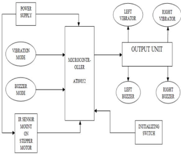
2.2 Block Diagram
The block diagram of our project is given in following figure. There are certain functions accomplished by these blocks. The description of blocks is as follows.
Figure 2- Block Diagram
2.2.1 Power supply
The power supply of our system is given by 9V battery. Microcontroller unit is fed by 5V supply. We generate 5V by using voltage regulator. 9V is given to sensor module. Basically, in sensor module we are using a stepper motor and an IR sensor. These both are needed to feed with power supply. 9V is used for the driver of stepper motor
2.2.2 Mode selecting switches
162 2.2.3 Sensor module
The sensor module is constructed using stepper motor and proximity IR sensor. The IR sensor is mounted on stepper motor. The motor rotates the IR sensor with stepangle 90 degree continuously. The sensor transmits infrared wave into the environment continuously. When the obstacle is present, the infrared wave reflected back to the sensor. The sensor receive reflected wave and produce corresponding signal. This signal is translated by microcontroller in appropriate form, used as the output to user. There are three portions, 30degree each, covered by the sensor module. One is left for left sided obstacle, second is front for front direction obstacles and the last one is right for right sided obstacles.
Figure 3- Sensor Module
2.2.4 Microcontroller unit
In microcontroller unit we use AT89S52 microcontroller. This is the main part of the project. Every command or instructions to the system is given by this part. It receives the signals from sensor and converts them into appropriate form, which can be used by output unit to provide or indicate the user about environment.
2.2.5 Output unit
The output unit controls the output modes given to the user. It contains circuitry, drivers and power supply, necessary to interface buzzer and vibrating motor to the microcontroller. It is noted that we need to use separate power supply unit for interfacing vibrating motor, because if we use the same supply, given to micro controller then back electro motive force generated by the vibrating motor may hang our microcontroller unit.
2.2.6 Initialization switch
163
3. TESTING AND RESULTS
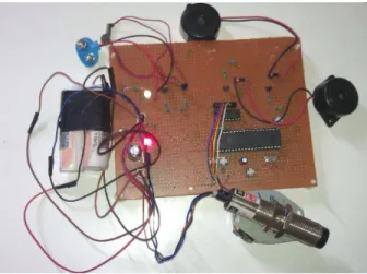
Infrared based sensor module, AT89S52 and output unites are tested individually as well as an integrated system. The main advantage of IR sensor is its small beam angle and sharp line of sight. As IR sensor works on principle of echo, study of its reflection properties on is very important. We studied the reflection properties of IR sensor on different surfaces. The tests are carried on concrete wall, static human body, wood and metal. Smooth surfaces can be detected from maximum detection range of IR sensors. Metal surface gives highest reflections and then concrete wall, wood and human body [1]. To evaluate the system we develop a test method. By folding the user eyes, we simulate the difficulties in navigation of the person. When the person moves with our system, then he is fully protected from the obstacles of environment. Below head area is secured by using walking stick and the near to head area is protected by sensing the obstacles with the help of our system. Microcontroller is used to make a complete programming and then is simulated at the Proteus. The distance between each vibration motor/buzzer embedded at the Cap must be far enough to avoid the user become confuse with the signal given. The project is low cost project with using the cheap but effective component like vibration motor/buzzer and cap because most blind men belong to lower income group.
Figure 4- Testing Circuitry Board
4. CONCLUSION
In this paper, we proposed and described a fully secured navigation system for blind people. The main advantage of the system is that it can make aware the user about obstacles of left side, right side and front side efficiently. We are using both the benefits of walking stick and detection by sensor module to provide complete protection into the environment. We are including walking stick into our system because it is most common method of walking for blind people so that it is most convenient for them. There are following advantages and limitations:
Advantages:
Accurate detection of obstacles of left, right and front side.
Very convenient for the users.
Detection of ground level to head level.
Low cost.
164 Limitations:
There are certain improvements required for following:
Recognition of objects.
Recognition of colours.
Size due to walking stick.
ACKNOWLEDGEMENT
I am grateful to Mr. Jaspal Singh, Principal Engineer, Centre for Development of Advanced Computing for his assistance in this project.
REFERENCES
[1]. Shripad S. Bhatlawande Jayanta Mukhopadhyay and Manjunatha Mahadevappa “Ultrasonic Spectacles and Waist-belt for Visually Impaired and Blind Person”, 2012.
[2]. Sylvain Cardin, Daniel Thalmann and Frederic Vexo “Wearable Obstacle Detection System for visually impaired People”, 2010.
[3]. M. Kassim, M. H. Jamaluddin, M. R. Yaacob, N. S. N. Anwar, Z. M. Sani and A. Noordin “Design and Development of MY 2nd EYE for Visually Impaired Person”, 2011.
[4]. Tatsuro UEDA1, Hirohiko KAWATA1, Tetsuo TOMIZAWA2, Akihisa OHYA1 and Shin’ich YUTA1 “Visual Information Assist System Using 3D SOKUIKI Sensor for Blind People– System Concept and Object Detecting Experiments –”, 2006
[5]. Dimitrios Dakopoulos and Nikolaos G. Bourbakis, Fellow, IEEE “Wearable Obstacle Avoidance Electronic Travel Aids for Blind: A Survey”, IEEE TRANSACTIONS ON SYSTEMS,MAN, AND CYBERNETICS—PARTC:APPLICATIONS AND REVIEWS, VOL. 40, NO. 1, JANUARY 2010.
[6]. Amit Kumar Rusha Patra, M. Manjunatha, J. Mukhopadhyay and A. K. Majumdar, “An Electronic Travel Aid for Navigation of Visually Impaired Persons”, 2011.
[7]. Stephen Karungaru, Kenji Terada and Minoru Fukumi “Improving Mobility for Blind Persons using Video Sunglasses”, 2005.
[8]. David T. Batarseh, Dr. Timothy N. Burcham, and Dr. Gary M. McFadyen, “An Ultrasonic Ranging System for the blind”, 1997.
Authors
Prashant Bhardwaj is pursuing Masters of Technology at C-DAC Mohali in Embedded System. He has obtained his Bachelor of Engineering degree in Electronics & Communication Engineering from Gautam Buddha Technical University, Lucknow in 2010. His research interests include Embedded System.