TNM Method Results Compared with Finite Element Analysis for
a 30 KW SCIM Motor
A. Ravi Prasad, Dr. K Prahlada Rao
Retired Scientific Officer (F), Bhabha Atomic Research Centre, Trombay, Mumbai-40085 Former In-charge Head, Department of Nuclear Energy, Pandit Deendayal Petroleum University, Gandhinagar, Gujarat
Professor, Department of Mechanical Engineering, JNTUA College of Engineering Anantapur- 515002 India
Abstract
The Thermal network model (TNM) of ten node 37 thermal resistances is considered as the highly detailed one for thermal distribution of all the TNM models. This model is reported to be the one that can take care of most of the complexities in geometry and estimation of convective heat transfer coefficients. Results obtained for the 30 KW motor using the above TNM model have been compared with that of Finite element Analysis using ANSYS. Listing of the MATLAB programs is presented as annexure.
I.
INTRODUCTION
The standard 10 node thirty seven TNM by Mellor and Turner [7]has been used to model the 30 KW motor the details of which are given in the table 1.
II.
THERMAL RESISTANCE
ESTIMATION OF MOTOR
COMPONENTS
Thermal network model consist of 10 nodes such as 1-Frame, 2-Stator Yoke,3-Stator Teeth,4-Stator Winding,5-Air Gap,6-End Winding,7-End Cap Air,8-Rotor Winding,9-Air,8-Rotor Iron,10-Shaft
Fig. 1 – The 10 node TNM model of SCIM motor
A. FRAME
R1 = 1
��� ℎ1 (1)
R2 = 1
� ℎ� � ��1 (2)
TABLE I
DETAILS OF 30 KW MOTOR [1] Power 30
KW
Connect ion
delta Core length
207
Air gap
0.80 Rotor diamete r
213 Stator diameter
334
η 0.927 Rated speed
1450 rpm
Rated torque
98.8 Nm Rotor
slots
43 Stator slots
48 Voltage (Line/Ph )
660/3 98.3 V Locati
on of loss
Stator core
Stator teeth
Stato r wind ing
Rotor bar
Rotor core
Loss (Watts )
467 165.40 738. 2
563 89.4
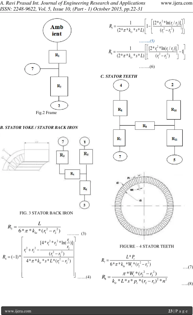
Fig.2 Frame
B. STATOR YOKE / STATOR BACK IRON
FIG. 3 STATOR BACK IRON
3 2 2
1 2
6 * *
la* (
)
L
R
k
r
r
……... (3)
2 2 1
1 2
2 2 2
1 2 2 2
1 2
4 2 2
1 2
[4*
*
*ln( )]
(
)
( 1)*
4* *
lr* * *(
)
r
r
r
r
r
r
r
r
R
k
s L
r
r
……(4)2
2 1 2
5 2 2
1 2
[2*
*ln( / )]
1
1
(2* *
l r* * )
(
)
r
r r
R
k
s L
r
r
……..(5) 2
1 1 2
6 2 2
1 2
[2* *ln( / )]
1
1
(2* *
l r* * )
(
)
r
r r
R
k
s L
r
r
……..(6)
C. STATOR TEETH
FIGURE – 4 STATOR TEETH
7 2 2
2 3
*
6* *
*
*(
)
t la t
L P
R
k
W
r
r
….(7)
2 2
2 3
8 2 2
2 3
*
*(
)
* * *
*(
) *
t
lr t
W
r
r
R
k
L s p
r
r
n
2 2 2
2 3
2 2 3
2 3 2 2
2 3
9 2 2
2 3
[4*
*
*ln( )]
(
)
( 1)*
4* *
lr* * *
t*(
)
r
r
r
r
r
r
r
r
R
k
L s W
r
r
…...(9)2
3 2 3
10 2 2
2 3
[2*
*ln( / )]
1
(2* *
* * *
)
(
)
t
l r t
P
r
r r
R
k
s L W
r
r
….(10) 2
2 2 3
11 2 2
2 3
[2*
*ln( / )]
1
(2* *
* * * )
(
)
t l r t
P
r
r r
R
k
s L W
r
r
……(11)
FIG. 5 STATOR WINDING
i
i 4 v
2
r 1
2*t
( *k *L*r *n)
(2* *k *L*f * )
1
n
R
…(12)
c 13
sc
(6*k *A *n)
L
R
…….(13)
4 14
i
i v r
4*t
( *k *L*r *n)
( *k
f *n)
1
*L*
R
....(14)
v 15
r
( *k
*n
1
*L*f
)
R
……..(15)
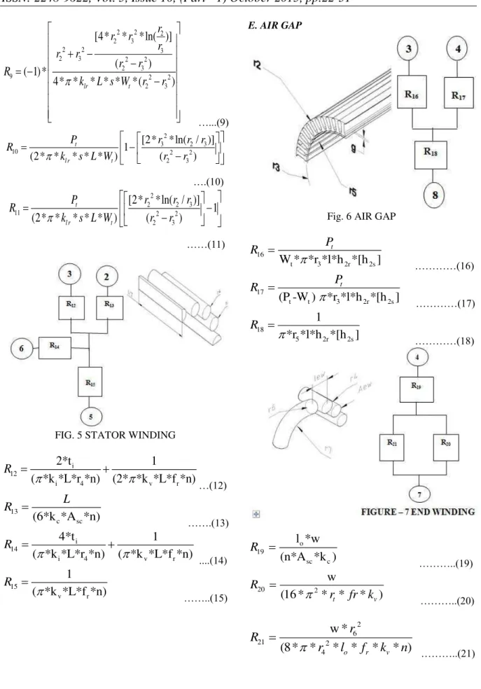
E. AIR GAP
Fig. 6 AIR GAP
t 3
16
2r 2s
W * *r *l*h *[h ]
t
P
R
…………(16)
t t 3 2r 2
1
s 7
(P -W ) *r *l*h *[h ]
t
P
R
…………(17)
5 2r 2s
18
*r *l*h *[
]
1
h
R
…………(18)
o
s 9
c c
1
l *w
(n*A *k )
R
………..(19)
20 2
w
(
16 *
* *
t*
v)
R
r
fr k
………..(20)
2 6
21 2
4
*
8*
w
(
*
*
o*
r*
v*
)
r
R
r
l
f
k
n
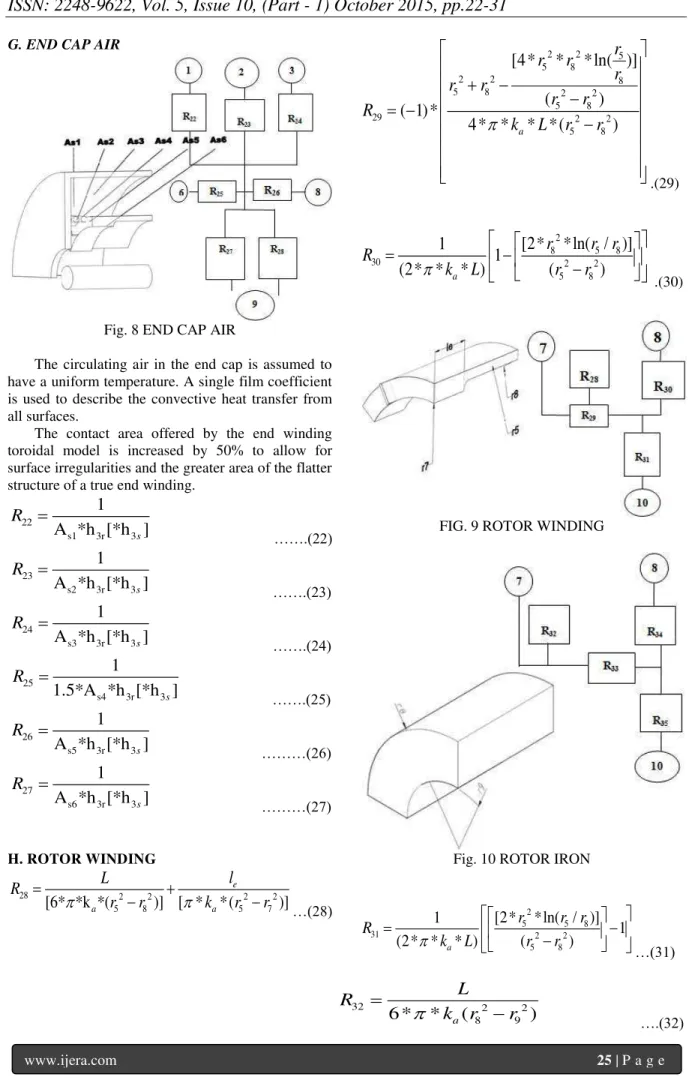
G. END CAP AIR
Fig. 8 END CAP AIR
The circulating air in the end cap is assumed to have a uniform temperature. A single film coefficient is used to describe the convective heat transfer from all surfaces.
The contact area offered by the end winding toroidal model is increased by 50% to allow for surface irregularities and the greater area of the flatter structure of a true end winding.
s1 3r 3
22
A *h
]
1
[*h
sR
…….(22)
s2 3r 3
23
A *h
]
1
[*h
sR
…….(23)
s3 3r 3
24
A *h
]
1
[*h
sR
…….(24)
s4 2
r 3
5
3
1.5*A *h [*
1
h ]
sR
…….(25)
s5 3r 3
26
A *h
]
1
[*h
sR
………(26)
s6 3r 3
27
A *h
]
1
[*h
sR
………(27)
H. ROTOR WINDING
28 2 2 2 2
5 8 5 7
[6* *k *(
)
]
[
*
*
(
)]
e
a a
l
L
R
r
r
k
r
r
…(28)2 2 5
5 8
2 2 8
5 8 2 2
5 8
29 2 2
5 8
[4*
*
*ln( )]
(
)
( 1) *
4* *
a* *(
)
r
r
r
r
r
r
r
r
R
k
L
r
r
.(29)
2
8 5 8
30 2 2
5 8
[2*
*ln( / )]
1
1
(2* *
a* )
(
)
r
r r
R
k
L
r
r
.(30)FIG. 9 ROTOR WINDING
Fig. 10 ROTOR IRON
2
5 5 8
31 2 2
5 8
[2*
*ln( / )]
1
1
(2* *
a* )
(
)
r
r r
R
k
L
r
r
…(31)32 2 2
8 9
6 *
*
a(
)
L
R
k
r
r
2 2 8
8 9
2 2 9
8 9 2 2
8 9
33 2 2
8 9
[4*
*
*ln( )]
(
)
( 1) *
4* *
lr* * *(
)
r
r
r
r
r
r
r
r
R
k
s L
r
r
…..(33)
2
9 8 9
34 2 2
8 9
[2*
*ln( / )]
1
1
(2* *
l r* * )
(
)
r
r r
R
k
s L
r
r
…..(34)2
8 8 9
35 2 2
8 9
[2*
*ln( / )]
1
1
(2* *
l r* * )
(
)
r
r r
R
k
L s
r
r
…..(35)I. SHAFT
9
36 2
(2* *k *L)
(2* *k r )
1
*
s s
m
l
R
……(36)
b
37 2
9
(4* *k *l )
(2*
k *r )
1
*
s
m s
l
R
……….(37)
FIG. 11 SHAFT
TABLE II LIST OF SYMBOLS
Symbols Name
Re Ohm Electrical Resistance (suffix s for stator and r for rotor)
I Amp. Current
W/(m2.K) Free convection heat transfer coefficient
between frame and ambient
h2r W/(m2.K) Rotating air-gap film coefficient
h2s W/(m2.K) stationary air-gap film coefficient
h3r W/(m2.K) Rotating end cap film coefficient
h3s W/(m2.K) Stationary end cap film coefficient
kla W/(m.K) Lamination axial conductivity
klr W/(m.K) Lamination radial iron conductivity
k’ W/(m.K) Equivalent thermal conductivity
kc W/(m.K) Copper conductivity ki W/(m.K) Slot liner conductivity kv W/(m.K) Varnish conductivity ka W/(m.K) Aluminium conductivity Ks W/(m.K) Shaft steel conductivity. Aframe mm2 Half of frame area As mm2 Slot Area Asc mm2 Copper wire area Av mm2 Varnish area
ASc mm2 Copper cross- section in slots
L m Stator length
l0 m Slot winding overhang hcont m Frame-core contact
coefficient r1 m Stator outer radius r2 m Tooth outer radius r3 m Tooth inner radius r4 m Equivalent winding radius r5 m Rotor outer radius
r6 m End winding cross section radius
r7 m End ring inner radius r8 m Equivalent rotor winding
radius
rt m End winding toroid radius ti m Insulation thickness Pt m Tooth pitch Wt m Stator tooth width n -- Number of slots
w -- Hot spot to mean temperature ratio
fr -- Radial conductivity factor le mm End ring width
lb mm Bearing housing width lm mm Distance of the bearing
centre to rotor mean As1 mm2 Surface area of end cap AS2 mm2 Surface area of stator iron AS3 mm2 Surface area of stator teeth, AS4 mm2 Surface area of end
winding
end-ring
AS6 mm2 Surface area of rotor iron
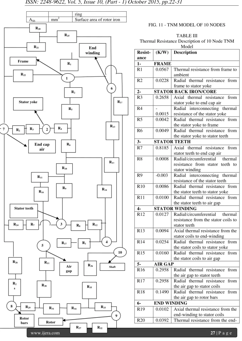
FIG. 11 - TNM MODEL OF 10 NODES
TABLE III
Thermal Resistance Description of 10 Node TNM Model
Resist- ance
(K/W) Description 1- FRAME
R1 0.0567 Thermal resistance from frame to ambient
R2 0.0228 Radial thermal resistance from frame to stator yoke
2- STATOR BACK IRON/CORE
R3 0.2658 Axial thermal resistance from stator yoke to end cap air R4
-0.0015
Radial interconnecting thermal resistance of the stator yoke R5 0.0042 Radial thermal resistance from
the stator yoke to frame
R6 0.0049 Radial thermal resistance from the stator yoke to stator teeth
3- STATOR TEETH
R7 0.8185 Axial thermal resistance from stator teeth to end cap air R8 0.0008 Radial/circumferential thermal
resistance from stator teeth to stator winding
R9 -0.003 Radial interconnecting thermal resistance of the stator teeth R10 0.0086 Radial thermal resistance from
the stator teeth to stator yoke R11 0.0100 Radial thermal resistance from
the stator teeth to air gap
4- STATOR WINDING
R12 0.0127 Radial/circumferential thermal resistance from the stator coils to stator teeth
R13 0.0094 Axial thermal resistance from the stator coils to end-winding R14 0.0254 Radial thermal resistance from
the stator coils to stator yoke R15 0.0160 Radial thermal resistance from
the stator coils to air gap
5- AIR GAP
R16 0.2958 Radial thermal resistance from the air gap to stator teeth
R17 0.2958 Radial thermal resistance from the air gap to stator coils
R18 0.1490 Radial thermal resistance from the air gap to rotor bars
6- END WINDING
R19 0.0102 Axial thermal resistance from the end-winding to stator coils R20 0.0392 Thermal resistance from the
end-6
R5 Stator yoke
Frame
End winding
R22
1
R37 R2
R1 R20
R21
R25
4 3
Shaft
Air gap R7
R24
R33 R35 R18
9
R32 R27
R29 R34
8
10
Rotor bars R2
8
R30 R26
R36 R1
5 R8 R12
R17 5
7
End cap air
R11
R14 R10
Rotor R31
R2 R3 2
3 R4
R19 R6
R13
3 R9 R16
winding to end cap air
R21 0.2522 Thermal resistance from the end-winding to end cap air
7- END CAP AIR
R22 0.0455 Axial thermal resistance from the end cap air to frame
R23 0.3716 Axial thermal resistance from the end cap air to stator yoke R24 1.2088 Thermal resistance from the end
cap air to stator teeth
R25 0.0614 Thermal resistance from the end cap air to end-winding
R26 1.1002 Thermal resistance from the end cap air to rotor end-rings
R27 0.7870 Thermal resistance from the end cap air to rotor iron
8- ROTOR WINDING
R28 0.0387 Axial thermal resistance from the rotor bars to end cap air
R29 -0.0001
Radial interconnecting thermal resistance of the rotor bars R30 0.0003 Radial thermal resistance from
the rotor bars to air gap
R31 0.0003 Radial thermal resistance from the rotor bars to rotor iron
9- ROTOR IRON
R32 0.4235 Axial thermal resistance from the rotor iron to end cap air
R33 -0.0037
Radial interconnecting thermal resistance of the rotor iron R34 0.0095 Radial thermal resistance from
the rotor iron to rotor bars R35 0.0138 Radial thermal resistance from
the rotor iron to shaft
10- SHAFT
R36 0.2158 Radial thermal resistance from the shaft to rotor iron
R37 0.2760 Axial thermal resistance from the shaft to frame through bearings
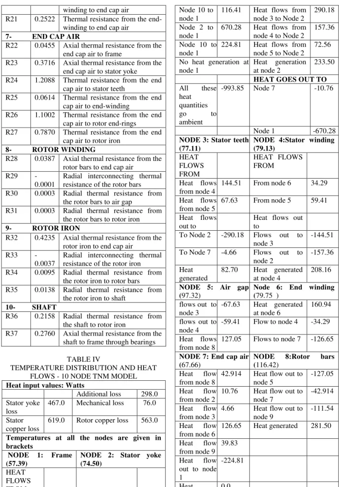
TABLE IV
TEMPERATURE DISTRIBUTION AND HEAT FLOWS - 10 NODE TNM MODEL
Heat input values: Watts
Additional loss 298.0 Stator yoke
loss
467.0 Mechanical loss 76.0
Stator copper loss
619.0 Rotor copper loss 563.0
Temperatures at all the nodes are given in brackets
NODE 1: Frame (57.39)
NODE 2: Stator yoke (74.50)
HEAT FLOWS FROM
Node 10 to node 1
116.41 Heat flows from node 3 to Node 2
290.18
Node 2 to node 1
670.28 Heat flows from node 4 to Node 2
157.36
Node 10 to node 1
224.81 Heat flows from node 5 to Node 2
72.56
No heat generation at node 1
Heat generation at node 2
233.50
HEAT GOES OUT TO
All these heat
quantities go to ambient
-993.85 Node 7 -10.76
Node 1 -670.28
NODE 3: Stator teeth (77.11)
NODE 4:Stator winding (79.13)
HEAT FLOWS FROM
HEAT FLOWS FROM
Heat flows from node 4
144.51 From node 6 34.29
Heat flows from node 5
67.63 From node 5 59.41
Heat flows out to
Heat flows out to
To Node 2 -290.18 Flows out to node 3
-144.51
To Node 7 -4.66 Flows out to node 2
-157.36
Heat generated
82.70 Heat generated at node 4
208.16
NODE 5: Air gap (97.32)
Node 6: End winding (79.75 )
flows out to node 3
-67.63 Heat generated at node 6
160.94
flows out to node 4
-59.41 Flow to node 4 -34.29
Heat flows from node 8
127.05 Flows to node 7 -126.65
NODE 7: End cap air (67.66)
NODE 8:Rotor bars (116.42)
Heat flow from node 8
42.914 Heat flow out to node 5
-127.05
Heat flow from node 2
10.76 Heat flow out to node 7
-42.914
Heat flow from node 3
4.66 Heat flow out to node 9
-111.54
Heat flow from node 6
126.65 Heat generated 281.50
Heat flow from node 9
39.83
Heat flow out to node 1
-224.81
Heat generated
NODE 9: Rotor Iron (115.75 ) Heat flow
from node 8
42.914 Heat flow from node 9
39.83
Heat flow from node 2
10.76 Heat flow out to node 1
-224.81
Heat flow from node 3
4.66 Heat generated 0.0
Heat flow from node 6
126.65
NODE 10: Shaft (89.49) Heat to
node 1
116.41 Heat from node 9 -116.41
No heat generation
REFERENCES
[1] PH Mellor, D Roberts, DR Turner, Lumped parameter thermal model for electrical IEE PROCEEDINGS-B/ Vol. 138, No. 5, 1/ 205-218/machines of TEFC design 1991
SEPTEMBER 1991
[2] Popove Lyudmila, Combined electromagnetic and thermal design platform for totally enclosed induction motors, MASTER’S THESIS
[3] ANSYS manual
Fig. 13 Thermal Distribution of 30 kw Motor
% ANNEXTURE – MATLAB program f2 = fopen('motor10nodes.txt','w'); %%All dimensions are in meter %%
%% Stator length and Stator outer radius %% length=0.2066; ra1 = 0.169
%% Tooth outer radius and Tooth inner radius %% ra2 = 0.1351; ra3 = 0.1075
%% Winding radius and Rotor outer radius %% ra4 = 0.0085718; ra5 = 0.1067
%% End winding cross section radius %% ra6 = 0.0273
%% End disk inner radius %% ra7 = 0.0889
%% Equivalent rotor winding radius %% ra8 = 0.0975
%% Shaft radius and Frame radius %% ra9 = 0.05510; raframe = ra1 + 0.02
%% End-winding toroid radius and No. of Slots %% rat = (ra2+ra3)/2; n = 48
%% Tooth pitch and Insulation Thickness %% pt = 0.0106; ti = 0.0005
%% End Winding length or Slot winding over hang lew = 0.025;lo=lew
%% distance of rotor centre to bearing centre %% lm = 0.15;
%% Bearing length and End cap length %% lb = 0.025; lendcap = 0.1281;
%% Length of Frame %% lframe = 0.23140;
%% Surface area of copper and Slot area %% Asc= 0.00019066; Aslot = ra4^2*pi;
%% Endcap contact area %%
As1 = (2*pi*raframe*lendcap) + (pi*raframe^2); %% End length %%
le = 0.0365; %% Short terms
ra12= ra1^2-ra2^2; ra23= ra2^2-ra3^2; ra57= ra5^2-ra7^2; ra58= ra5^2-ra8^2; ra89= ra8^2-ra9^2;
%% Contact Area of stator iron %% As2 = pi*(ra12);
%% Contact area of stator teeth %% As3 = pi*(ra23) - Aslot*n;
%% Contact area of endwinding %% As4 = 2*pi*ra6*2*pi*rat;
% As4 = 2*pi*ra6;
hsum = (((ra5*2) - ra7*2 )/(2));
%% Contact area of rotor end winding %% As5 = pi*(ra5^2 -((2*ra5-2*(hsum))/2)^2); %% Contact area of rotor %%
As6 = pi*(((2*ra5-2*(hsum))/2)^2-(ra9^2)); %% Contact area of end ring %%
As7 = (2*pi*(ra57)+2*pi*ra5*le); %% Surface area of frame %%
Aframe = pi*raframe^2 + 2*pi*raframe*lframe; %% Heat transfer coefficient %%
%% Frame core contact coffi %% hcont = 400;
%% Lamination stacking factor %% s = 0.97;
fr = 2.5;
%% Hotspot to mean temp %% w = 1.5;
%% Lamination axial and iron conductivities %% kla = 4; klr = 39;
%% Shaft steel and copper conductivities %% ks = 40; kc = 400;
%% Slot liner and varnish conductivities %% ki = 0.8; kv = 0.8;
%% Aluminium and air conductivities %% ka = 237; kair = 0.026;
%% Convection bt frame and ambient %% h1 = 15.0952;
%% rotating airgap film %% h2r = 96.8975;
%% Stationary airgap and end cap films %% h2s = 65; h3s = 15.5;
%% rotating endcap air film %% h3r = 83.0951;
%losses %%
pfys = 467.00; pfes = 76.00;
pad = 298.00; pcus = 619.00; pcur = 563.00; %% Resistance %%
r1 = 1/(2*h1*1.51*Aframe); r2 = 1/(pi*hcont*length*ra1); r3 = length/(6*pi*kla*ra12);
r4_c= 4*ra1^2*ra2^2*log(ra1/ra2)/ra12; r4_d= 4*pi*klr*length*s*ra12;
r4 = -1*(ra1^2 + ra2^2 -r4_c)/r4_d; r5_a= 2*ra2^2*log(ra1/ra2)/ra12; r5_b = (1-r5_a);
r5= r5_b/(2*pi*klr*length*s); r6_a = 2*ra1^2*log(ra1/ra2)/ra12;
r6= (r6_a -1)/(2*pi*klr*length*s);Wt = 0.0053; r7 = length*pt/(6*pi*kla*Wt*ra23);
r8 = pi*Wt*ra23/(klr*length*s*pt*(ra2-ra3)^2*n^2); r9_a= 4*ra2^2*ra3^2*log(ra2/ra3)/ra23 ;
r9_b = -pt*(ra2^2 + ra3^2 -r9_a); r9= r9_b/ (4*pi*klr*length*s*Wt*ra23); r10_a= 2*ra3^2*log(ra2/ra3)/ra23; r10_b= 2*pi*klr*length*s*Wt; r10 = pt*(1-r10_a)/r10_b;
r11_a= 2*ra2^2*log(ra2/ra3)/ra23; r11_b= 2*pi*klr*length*s*Wt; r11 = pt*(r11_a -1)/r11_b;
r12_a = 2*ti/(pi*ki*length*ra4*n); r12_b = 1/(2*pi*kv*length*fr*n); r12 = r12_a + r12_b;
r13 = length/(6*kc*Asc*n);
r14_a = 4*ti/(pi*ki*length*ra4*n); r14_b= 1/(pi*kv*length*fr*n); r14 = r14_a + r14_b;
r15 = 1/(pi*kv*length*fr*n); r16 = pt/(Wt*pi*ra3*length*h2r); r17 = pt/((pt-Wt)*pi*ra3*length*h2r); r18 = 1/(pi*ra5*length*h2r);
r19 = lo*w/(n*Asc*kc); r20 = w/(16*pi^2*rat*fr*kv);
r21 = w*ra6^2/(8*pi*ra4^2*lo*fr*kv*n); r22 = 1/(As1*h3r); r23 = 1/(As2*h3r); r24 = 1/(As3*h3r); r25 = 1/(1.5*As4*h3r); r26 = 1/(As5*h3r); r27 = 1/(As6*h3r); r28_a = length/(6*pi*ka*(ra58));
r28_b= le/(pi*ka*(ra57)); r28= r28_a + r28_b; r29_a= 4*ra5^2*ra8^2*log(ra5/ra8)/ra58; r29_b = 4*pi*ka*length*ra58;
r29 = -1*(ra5^2 + ra8^2 -r29_a)/r29_b; r30_a= 2*ra8^2*log(ra5/ra8)/ra58; r30_b= 2*pi*ka*length;
r30 = (1-r30_a)/r30_b;
r31_a= 2*ra5^2*log(ra5/ra8)/ra58; r31_b= 2*pi*ka*length;
r31 = (r31_a -1)/r31_b; r32 = length/(6*pi*kla*ra89);
r33_a= 4*ra8^2*ra9^2*log(ra8/ra9)/ra89; r33_b= 4*pi*klr*length*s*ra89;
r33 = -1*(ra8^2 + ra9^2 -r33_a)/r33_b; r34_a= 2*ra9^2*log(ra8/ra9)/ra89; r34_b= 2*pi*klr*length*s;
r34 = (1-r34_a)/r34_b;
r35_a= 2*ra8^2*log(ra8/ra9)/ra89; r35_b= 2*pi*klr*length*s;
r35 = (r35_a-1)/r35_b;
r36_a=1/(2*pi*ks*length);r36_b= /(2*pi*ks*ra9^2); r36 = r36_a + r36_b;
r37_a = 1/(4*pi*ks*lb); r37_b= /(2*pi*ks*ra9^2); r37 = r37_a + r37_b;
%% Thermal conductances %%
g12 = 1/(r2+r4+r5); g17 = 1/ r22; g110 = 1/r37; g11 = g12 +g110 + g17+(1/r1);
g23 = 1/(r4+r6+r9+r10); g24 = 1/(r14+r6+r4); g25 = 1/(r4+r6+r10+r11+r16);
g27 = 1/(r3+r23); g22 = g12 +g23+g27+g24; g34 = 1/(r8+r12);
g35 = 1/(r9+r11+r16); g37 = 1/(r7+r24); g33 = g23 + g34 +g37 + g35;
g45 = 1/(r15+r17); g46 = 1/(r13+r19); g44 = g24 + g34 +g45 +g46;
g58 = 1/(r18+r29+r30); g55 = g35 +g45 + g58 ; r67_a = r20*r21/(r20+r21);
g67 = 1/(r67_a + r25); g66 = g46 + g67; g78 = 1/(r26 +r28); g79 = 1/(r32+r27); g77 = g17 + g27 + g37 + g67 + g78 + g79 ; g89 = 1/(r29+r31+r33+r34);
g88 = g58+g78+g89;g910 = 1/(r33+r35+r36); g99 = g89 + g79 + g910; g1010= g910+g110; %% Matrix %%
-g110 0 0 0 0 0 0 0 -g910 g1010 ]; p = [0; pfys/2; (pfes+0.3*pad)/2; ((pcus*0.48+0.4*pad)/2); 0;
pcus*0.52/2; 0; pcur/2; 0.3*pad/2; 0]; t=g\p;
f_Row= [g11 -g12 0 0 0 0 -g17 0 0 -g110 ]; s_Row= [ -g12 g22 -g23 -g24 0 0 -g27 0 0 0] ; t_Row= [ 0 -g23 g33 -g34 -g35 0 -g37 0 0 0 ]; fo_Row=[0 -g24 -g34 g44 -g45 -g46 0 0 0 0 ]; fi_Row=[ 0 0 -g35 -g45 g55 0 0 -g58 0 0; ]; si_Row=[ 0 0 0 -g46 0 g66 -g67 0 0 0 ]; se_Row=[-g17 -g27 -g37 0 0 -g67 g77 -g78 -g79 0]; ei_Row=[ 0 0 0 0 -g58 0 -g78 g88 -g89 0 ]; ni_Row=[ 0 0 0 0 0 0 -g79 -g89 g99 -g910 ] ; te_Row=[ -g110 0 0 0 0 0 0 0 -g910 g1010 ]; fprintf(f2,'\n r1 r2 r3 r4 r5 r6 \n'); fprintf(f2,'%9.3f',r1,r2,r3,r4,r5,r6);
fprintf(f2,'\n r7 r8 r9 r10 r11 r12 \n'); fprintf(f2,'%9.3f',r7,r8,r9,r10,r11,r12);
fprintf(f2,'\n r13 r14 r15 r16 r17 r18 \n'); fprintf(f2,'%9.3f',r13,r14,r15,r16,r17,r18);
fprintf(f2,'\n r19 r20 r21 r22 r23 r24 \n'); fprintf(f2,'%9.3f',r19,r20,r21,r22,r23,r24);
fprintf(f2,'\n r25 r26 r27 r28 r29 r30 \n'); fprintf(f2,'%9.3f',r25,r26,r27,r28,r29,r30);
fprintf(f2,'\n r31 r32 r33 r34 r35 r36 r37 \n'); fprintf(f2,'%9.3f',r31,r32,r33,r34,r35,r36,r37); fprintf(f2, '30KW,440V,50HZ,3-Ph SCIM\n'); fprintf(f2, *********************************'); fprintf(f2, '\nOutput Data:');
fprintf(f2, '\n---');
fprintf(f2, '\n heat input values:');
fprintf(f2,'stator yoke loss %5.1f, iron loss=%5.1f,additional loss%5.1f',pfys,pfes,pad); fprintf(f2,'stator copper loss=%5.1f, rotor copper loss=%5.1f',pcus,pcur);
fprintf(f2, '\n---conductivity matrix '); fprintf(f2,'\n---conductivitymatrix ');fprintf(f2,'\n'); fprintf(f2,'%6.1f',f_Row);fprintf(f2,'\n');
fprintf(f2,'%6.1f',s_Row);fprintf(f2,'\n'); fprintf(f2, '%6.1f',t_Row);fprintf(f2,'\n'); fprintf(f2, '%6.1f',fo_Row);fprintf(f2,'\n'); fprintf(f2, '%6.1f',fi_Row);fprintf(f2,'\n'); fprintf(f2, '%6.1f',si_Row);fprintf(f2,'\n'); fprintf(f2, '%6.1f',se_Row);fprintf(f2,'\n'); fprintf(f2, '%6.1f',ei_Row);fprintf(f2,'\n'); fprintf(f2, '%6.1f',ni_Row);fprintf(f2,'\n'); fprintf(f2, '%6.1f',te_Row);fprintf(f2,'\n'); fprintf(f2, '\nTemperature rise in the nodes'); fprintf(f2,'%7.2f',t);
fprintf(f2, '\nHeat in puts in the nodes'); fprintf(f2,'%7.2f',p);
%Heat flows around node 1 ht12 = (t(1)-t(2))/(r2+r4+r5); ht17 = (t(1)-t(7))/ r22; ht110 = (t(1)-t(10))/r37;
ht11 = ht12 +ht110 + ht17+(1/r1);
fprintf(f2,'\n ht12 ht17 ht110 ht11 \n');
fprintf(f2,'%9.3f',ht12,ht17,ht110,ht11);
%Heat flows around node 2 (ht12 is already defined) ht23 = (t(2)-t(3))/(r4+r6+r9+r10);
ht24 = (t(2)-t(4))/(r14+r6+r4);
ht25 = (t(2)-t(5))/(r4+r6+r10+r11+r16); ht27 = (t(2)-t(7))/(r3+r23);
ht22 = ht12 +ht23+ht27+ht24;
fprintf(f2,'\n ht12 ht23 ht24 ht25 ht27 ht22 \n'); fprintf(f2,'%9.3f',ht12,ht23,ht24,ht25,ht27,ht22); %Heat flows arnd node 3 ( ht23 is already defined) ht34 = (t(3)-t(4))/(r8+r12);
ht35 = (t(3)-t(5))/(r9+r11+r16); ht37 = (t(3)-t(7))/(r7+r24); ht33 = ht23 + ht34 +ht37 + ht35;
fprintf(f2,'\n ht23 ht34 ht35 ht37 ht33 \n'); fprintf(f2,'%9.3f',ht23,ht34,ht35,ht37,ht33);
%Heat flows arn node 4 (ht24 and ht34 defined) ht45 = (t(4)-t(5))/(r15+r17);
ht46 = (t(4)-t(6))/(r13+r19); ht44 = ht24 + ht34 +ht45 +ht46;
fprintf(f2,'\n ht24 ht34 ht45 ht46 ht44 \n'); fprintf(f2,'%9.3f',ht24,ht34,ht45,ht46,ht44);
%Heat flows arnd node 5 (ht35 and ht45 are defined) ht58 = (t(5)-t(8))/(r18+r29+r30);
ht55 = ht35 +ht45 + ht58 ;
fprintf(f2,'\n ht35 ht45 ht58 ht55 \n'); fprintf(f2,'%9.3f',ht35,ht45,ht58,ht55);
%Heat flows around node 6 (ht46 is already defined); r67_a = r20*r21/(r20+r21);
ht67 = (t(6)-t(7))/(r67_a + r25); ht66 = ht46 + ht67;
fprintf(f2,'\n ht46 ht67 ht66 \n'); fprintf(f2,'%9.3f',ht46,ht67,ht66);
%Heat flows around node 7 (ht17, ht27, ht37,ht67 are %already defined)
ht78 = (t(7)-t(8))/(r26 +r28); ht79 = (t(7)-t(9))/(r32+r27);
ht77 = ht17 + ht27 + ht37 + ht67 + ht78 + ht79 ; fprintf(f2,'\n ht17 ht27ht37 ht67 ht78 ht79 ht77 \n'); fprintf(f2,'%9.3f',ht17,ht27,ht37,ht67,ht78,ht79,ht77); %Heat flows around node 8 (ht58, ht78 are defined) ht89 = (t(8)-t(9))/(r29+r31+r33+r34);
ht88 = ht58+ht78+ht89;
fprintf(f2,'\n ht58 ht78 ht89 ht88 \n'); fprintf(f2,'%9.3f',ht58,ht78,ht89,ht88);
%Heat flows around node 9 (ht89, ht79 are defined) ht910 = (t(9)-t(10))/(r33+r35+r36);
ht99 = ht89 + ht79 + ht910;
fprintf(f2,'\n ht89 ht79 ht910 ht99 \n'); fprintf(f2,'%9.3f',ht89,ht79,ht910,ht99); %Heat flows around node 9
ht1010= ht910+ht110;
![Fig. 1 – The 10 node TNM model of SCIM motor A. FRAME R 1 = 1 � �� ℎ 1 (1) R 2 = 1 � ℎ � � � � 1 (2) TABLE I DETAILS OF 30 KW MOTOR [1] Power 30 KW Connection delta Core length 207 Air gap](https://thumb-eu.123doks.com/thumbv2/123dok_br/18394671.357962/1.893.448.795.493.827/model-frame-table-details-motor-power-connection-length.webp)