Abstract— Abstract in this paper, a generic virtual control system development methodology for virtual commissioning has been applied to illustrate the reduction in time and effort that can be gained by using model based control development with automatic code generation compared to the direct iterative development. Compared to the other related works which require no manual coding, the methodology used here uses generic and general purpose tool, Matlab, to generate codes in IEC61131-3 that can be compiled and downloaded to a wide range of PLC’s. Using an illustrative case to cover each steps in the development phase, the paper describes the advantages of model based methodology.
Index Terms—PLC, Model Based Design, Virtual Control, Automation.
I. INTRODUCTION
apid deployment of manufacturing systems is a crucial step to increase the overall competitiveness in a dynamic manufacturing environment. Experience has shown that control system development and commissioning is a critical activity in the overall system deployment time. For instances, it has been reported [1] that 70% of the time is spent to debug and eliminate errors in control systems during commissioning of the manufacturing system. To decrease this, Virtual Commissioning (VC) has become an established method and a number of tools and architectures have been developed in the last two decades.
Virtual Commissioning (VC) as a concept is understood as virtual implementation and validation of industrial automation systems using virtual tools prior to the implementation of the real system.
Application of model based approaches with rapid generating and compiling tools for IEC standard PLC code significantly reduce the PLC development time.
Three development stages can be recognized in the implementation of VC: development of the control codes, virtual verification of the codes generated, and finally virtual commissioning. Each of these development stages have their own advantages in contributing to the reduction of the development time and also have their limitations and challenges inherent to them. In addition, it will enhance the
Manuscript received January 10, 2013; revised January 22, 2013. This work was supported by VINNOVA through the Holistic Simualtion and Optimization (HSO). Virtual Control System Development Platform with the application of PLC Device
Mosharraf Hossain is with the Department of Production Engineering and Management, The Royal Institute of Technology (KTH), SE-100 44 Stockholm, Sweden (e-mail: [email protected]).
Daniel T. Semere is with the Department of Production Engineering and Management, The Royal Institute of Technology (KTH), SE-100 44 Stockholm, Sweden (e-mail: [email protected]).
reusability of existing modules, which is not possible in manual PLC programming.
In this paper, a generic virtual control system development platform for VC has been applied to illustrate the reduction in time and effort gained by using model based control development with automatic code generation compared to the direct iterative development.
The comparative savings obtained are presented with respect to the steps in the model based approaches namely: behavior modeling by discrete event formalism, direct control code generation from the model, simulation based verification of the generated code, validation of the code using a 3D model of the system and virtual commissioning of the control using the real PLC controller and the virtual model.
The advantages gained can be seen from the overall system development perspective in order to highlight the significance of initiating and developing the control system prior to the actual real world installation of the system components on the shop floor. This is all the more important as more frequent changes are made in product design that requires changes in the control system.
The paper is organized as follows Section 2 describes virtual control system and briefly presents the state-of the art; section 3 provides generic virtual control system framework and their components; Section 4 shows an illustrated case study of the virtual control system development, automatic control code generation and virtual implementation.
II. VIRTUAL CONTROL SYSTEM AND BRIEFLY PRESENT
STATE-OF-ART
The research on manufacturing cell control development is extensive and is wide in scope. Since the last decade, model based approaches with rapid control code generation and verification has been an active research area in which new tools and methods have been proposed. The majority of these researches are based on automated and integrated solutions comprising the simulation, code generation and validation of the control system. Commercial tools for such type of integrated solutions are already available today [2]. The emergence of the IEC 61131-3 standard and compatible development tools such as CoDeSys [3] ISaGRAF [4] have facilitated for generic and nonproprietary tools and platforms to emerge.
The steps followed in model based PLC development approach are: capturing the logics by discrete event modeling formalism, direct control code generation from the model, simulation based verification of the generated code, validation of the code using a 3D model of the system and
Virtual Control System Development Platform
with the Application of PLC Device
M. Hossain and D.T. Semere
virtual commissioning of the control using the real PLC controller and the virtual model. The review of related work is presented in this section with respect to these steps.
Application of petri-nets, Timed Automata (TA), state flow charts, and Unified Modeling Language(UML) have extensively been used in sequential system behavior modeling. The use of petri nets, with their capability to capture state transitions, concurrency and synchronized interactions among system components has made them the focus for early works towards model based automation system development.
Grafcet [5], rooted in petri nets and even referred as a variant of a petri net, has been widely used in the representation of sequential input output relationships. Grafcet is often loosely equaled with Sequential Function Chart (SFC), one of the languages in IEC 61131-3 standard, due to their similarities in graphical representations and semantics. Despite its wide application, reported work on automated control code generation from Grafcet/SFC is limited to C or VHDL.
Signal Interpreted Petri Nets, SIPN, is another petri net based PLC development method to which a SIPN Editor is developed to generate an Instruction List [6] . The aim of this editor is to allow one to automatically transform a graphically edited Signal Interpreted Petri Nets (SIPN) into PLC code using an Instruction List (IL). The method though can capture complex IO relationships, the inherently laborious mapping of the graphical model to its semantic format before the model checking and the subsequent verification of the model makes the system less efficient in the reduction of the total development time and less appealing for industrial PLC programmers.
Similar efforts of automated code generation is also been reported using Timed-Message Based Part State Graph t -MPSG, a variant of finite state automata [7]. The MPSG simulator verifies and translates the input output relation into an IEC 61131-3 complaint PLC program which can be compiled and downloaded to either a PLC emulator or a PLC device. The approach is sound however the model lacks completeness of the system model since only sequential behaviors are captured by MPSG. This demands
addition of other run time features on the generated code program afterwards.
Other related works which uses UML as modelling formalism are summarized in [8]. Han et al [9] proposed a methodology in which UML’s is used for design, simulation and automatic generation of ladder logic. The paper, though discusses the development stages towards automatic PLC code generation, emphasis was given more on the application software development.
The related work discussed so far are those which cover the whole development stages with no or minimum manual intervention to generate the PLC code. The literature on proposed methodologies with manual translations and programming are vast and are not included here.
Industrial application of these approaches is still a long way to go and thus far use is limited to training or educational purpose [10], [11]. Use of established and industry standard development tools, neutral formats information exchange and integration and enabling module reusability will enhance the industrial acceptance of VC which our methodology is addressing. However in this paper only the modeling and code generation part is presented.
III. VIRTUAL CONTROL SYSTEM FRAMEWORK
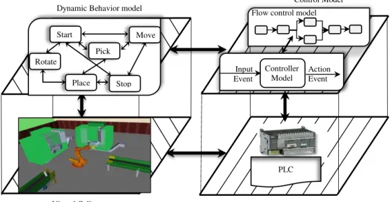
In order to resolve the limitations of previous frameworks, this control system development proposed a generic framework to reduce development cost and effort. This framework in Fig. 1 contains four different sections i) Cell controller model, ii) Dynamic behavior model, iii) programmable controller device, and iv) virtual cell.
The control software platform is the heart of control system development. The platform must be user friendly by providing interactive graphical user interface and error handler that will require less training for new users and easy to find errors. The simulator must allow event-driven system to design reactive systems with verification and validation facility and graphical visualization. Model complexity will be minimized by applying hierarchical modeling techniques so that bigger subsystem is decomposed into smaller subsystem. The platform should support modular approach to accommodate different subsystem and modules change
Dynamic Behavior model
Virtual Cell
Controller Model Input
Event
Action Event Flow control model
Start
Stop Move
Rotate
Pick
Place
PLC
Fig. 1. Virtual control system framework
whenever needed. This application must provide a data vault and reusable library to store information and developed components which will enhance the life cycle of software components. The generic platform should have the ability to generate codes for controller devices and contain drivers, open and standard communication interfaces that will allow integrating with other application tools and drives. However, more detail illustration of each component of the virtual control system development framework are given below:
A. Cell Controller Design
Model based control system development is proposed in this paper to design control behavior model as well as material flow model since, it simplifies the design process and reduces time by avoiding manual coding. This approach allows reuse of block sets and modules which reduces repetitive task and easy to configure the control system. With the help of interactive graphical user interface, it is easy to find the errors in the early stages of development which will save a lot of time and manual effort. At the beginning of system configuration, manufacturing companies would be interested to see the feasibility of a new configuration or reconfiguration of existing facility by analyzing product flow related properties. Development of control model and flow model is designed using different proprietary application tools, hence it demands more expertise, man hours, manual transfer of information causes human errors and sometimes unable to integrate. Therefore flow control model should be developed along with controller model in a generic model based development platform.
Typically, the model building process is started after procurement. Most of the company depends on control system builder or supplier due to heterogeneity of devices and application tools. To rectify those matters, the virtual control system development offers model building parallel with concept development to commission equipment with shorter period of time. Controller model will be designed to control intended production equipment by handling information and signal to get desired control behavior. In this model, equipment control design and system control design are performed concurrently to achieve intended system behavior as a whole. Since controller code will be generated from controller model and transferred to controller devices, controller model must satisfy constrains of code generation compiler. The domain of modeling concerned with generic structure to expedite reuse of models, library functions and ease of integration with other applications.
B. Dynamic Behavior Model
Dynamic behavior model should provide a model based interface between controller model and virtual cell or between controller devices and virtual cell to validate developed control code in an efficient way. The behavior model should coordinate and synchronize among the different parts or equipment by sequential or parallel operations. With the help of interactive graphical user interface, one can identify rapidly logical errors and dead locks in premature control system development phase. In addition, it should provide the solution of what should be moved, how much should it be moved and how should it
move. By using functional block library, the dynamic behavior model converts controller commands to virtual cell emulator commands with less effort and less time. A simulation environment helps to quick and efficient verification of the functionality of controller model and virtual cell. Similarly real controller’s functionality will be verified by using the same model along with virtual cell. Constrains and limits of movements must be specified to avoid unusual behavior of components and not to exceed machine specifications. Therefore, this model should allow designing optimum material flow in a cell and reducing validation time of control behavior.
C. Virtual Cell Design
The purpose of the virtual cell is to validate control code in advance of real control system implementation to reduce commissioning time and to avoid damaging of expensive equipment. Virtual cell should build by means of the 3-Dimensional (3D) model with interactive vector graphics that should emulate exactly as physical equipment. The 3D model of equipment must be translated into a generic format, specifically Virtual Reality Markup Language (VRML) because of wider applicability, conciseness and ease of simulation. It was designed to exchange of 3D CAD model from CAD systems with World Wide Web in mind. Thus, the VRML model is also easy to simulate through the internet. User can customise movable components, their motions and properties for better functionality. After specifying all properties, all equipment should organise on a layout at a desired position to avoid collusion and to design efficient material flow. In this level, better layout design can be achieved and collusion can be detected before commissioning the real equipment. In addition, with the help of simulation, the validation of controller functionality is achieved at a fast pace by emulating the virtual components.
D. Automatic PLC code generation and virtual commissioning
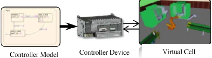
Programmable logic controller (PLC) has been widely used by the automation engineer for a couple of decades because of their reliable control system design and safety critical operation. Therefore, ConSDeP platform proposes a virtual commissioning of the control using real PLC controller and virtual model which is shown in Fig.2. In this platform, control code will be generated automatically to resolve software complexity and to avoid human error. A compiler is used to generate control code with test bench to reduce dead codes and errors as well as to get verification support before execution. Hence, the control program has to be converted into most widely accepted PLC programming standard IEC61131-3 which will improve fidelity between higher level model and lower level PLC controller devices.
Virtual Cell Controller Device
Controller Model
Controller Model
Dynamic Behavior model
Virtual Cell
3D animation toolbox
Fig. 4. Dynamic behavior model with interface to virtual cell
The IEC61131-3 standard specifies syntaxes and semantics of a unified suite of programming language for Programmable devices.
Generated control code is compiled and downloaded into PLC controller devices. Communication between controller device and virtual cell is made via standard communication protocol such as Ethernet/IP, Modbus, and OPC. However, the code is executed in real controller device but in non-real time. Virtual cell model generates inputs based on mathematical algorithm and passed those input to controller device. Once the target controller receives the inputs; it computes the outputs which are passed back to virtual cell model for computation as an actuator commands. The plant model then continues to simulate while the target processor waits for new inputs. This process is useful to identify processor related errors, memory limitations which can’t be detected only in modeling environment. It is an effective way to evaluate functional behavior in response to real time controller signals. To test fidelity, performance and robustness of controller code, one can test in different controller devices with different communication protocols. As a whole automatic hardware independent code generation and non-real time testing using the real controller will enhance the efficiency and speed of developing new automation solutions.
IV. ACASE STUDY
A case study has been coined to implement virtual Control System Development (ConSDeP) framework describes in this literature. The case study has considered a manufacturing cell which contains two machine tools, one robot and two material handling conveyors. Simulink/Matlab application tool is chosen to develop the control system according to the described framework. Different toolbox of Simulink has been used to model discrete, continuous or both two (hybrid) events and to visualize the dynamic behavior of the system.
A. Cell Controller Design
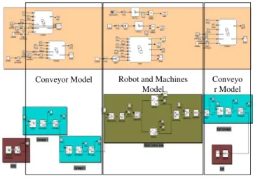
Model based design is adopted to model the manufacturing control system design because it simplifies the development by facilitating a common environment and communication among the different applications. With the help of interactive user interface, automation engineers can find the errors in the earlier stage of development and compare the model output against the requirements. By the use of flow model the production engineer can decide whether the investment for new development or reconfiguration is feasible or not. The flow model and capacity analysis of the manufacturing cell is modeled in fig. 3(a) using model based SimEvents block sets of Simulink. The level of abstraction of the model was sufficiently detailed to capture all flow related properties, bottleneck identification, utilization of equipment, output quantity etc.
Controller model fig. 3(b) has been developed using Stateflow Charts along with flow model to capture the control behavior of individual components or objects. The controller model captures all events both internal and external such as sensors signals, actuators command, logical expression, initial conditions, internal events, fault
detection, etc. The control specifications form the basis for developing the control logic programs. Exception handling logic was added to handle unwanted behavior of the control system. This control logic is the core mechanism to integrate the simulation environment, control system environment and emulation of the system. Hierarchical and modular approach is used to design the control system development. In this stage of modeling PLC code generation aspects and constrains have been considered with great attention because Simulink PLC coder can generate code only for a limited number of blocks in Simulink blocks, Stateflow chart without timing attributes and embedded Matlab functions. Efficient control design has been performed by utilizing library functions and functional blocks of Simulink which help to reduce development time.
B. Dynamic Behavior Model
Dynamic behavior model of the manufacturing cell is prepared using StateFlow Chart of Simulink. In this model, equipment is modeled to show moving parts, linear or circular interpolation of different parts of machines, conveyor, and robots. This model receives the command from StateFlow control model and feeds signals to 3D animation block sets that are used to emulate the virtual cell which is shown in fig.4. The model is developed by identifying the operations activity that is either sequential or parallel. Each equipment can operate independently but it must follow depending activity of predecessors or successors. Priority has been provided for robot movement to avoid deadlock error and efficient material handling.
In this model, different integration and triggering functions are used to get incremented and decremented value with time and to activate or deactivate movable parts. This model is validated by emulating the virtual cell or value plotting by scope block. At the beginning, this model
Fig. 3. a) Flow model (Bottom) b) Controller model (Top) Conveyor Model Robot and Machines
Model
is used for simulation purpose; later on the same model is used to emulate the real controller device along with device driver blocks.
C. Virtual Cell Design
Virtual cell is designed using Virtual Reality Modeling Language (VRML) along with 3D animation toolbox of Simulink. VRML is standard file formats for representing 3-dimensional model with interactive vector graphics. To make the virtual cell, 3D CAD model of manufacturing resources are converted to virtual really model and imported into 3D animation toolbox in Fig.5. VRBuild Version 2 were used to edit VRML model such as specify the parts
that will be in motion, assign positions, colors, lighting, visibility etc. Then, all necessary equipment were placed on the layout according to requirements and dimensional constrains. In this case study, robot movements, parts movements on the conveyors, machining operation and safety door control have been modeled to show the dynamic and functional behavior. 3D animation block sets of Simulink provides necessary coordinates, velocity, traveling distance, angular velocity, necessary logics etc. in coordination with dynamic behavior model. With the help of 3D animation user interface, one can navigate different areas of virtual cell to verify functionality and to control over the simulation.
D. Automatic PLC Code Generation
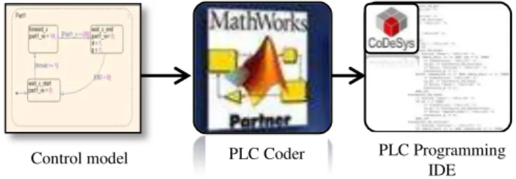
To generate hardware-independent IEC61131-3 standard programmable logic code from controller model, Simulink PLC Coder has been used. This coder generates only IEC 61131 structured text from Simulink models, Stateflow charts, and Embedded MATLAB functions by using limited number of blocks [12]. Thus, we need to verify if all the used blocks and codes follows PLC coder specifications. The complier generates structured text in PLCopen Extensible Markup Language (XML) standard and some other integrated development environments (IDEs) formats. As a result, this generated program can be easily compiled and deployed to numerous programmable logic controller (PLC) and programmable automation controller (PAC) devices. In this case study, Codesys software from 3s-software is used to validate the control code generated from controller model. Unlike the other IEC61131-3 programming tools, Codesys supports all five programming languages with easy handling and operational functionality. Codesys is also supports a large number of PLC processors. Automatic PLC code generation process is shown in fig. 6. In addition, PLC code generator produces test bench which help to validate the PLC code before implementation. Whenever the change in the controller model is made and
separate programmable logic code is generated within few seconds and validated again using the controller specified tools (IDEs). Consequently, automatic code generation reduces almost total time that was used by automation engineer to write programs for programmable logic control devices. For an instance, DEIF A/S has reported [13] by means of automatic PLC code generation, 40% of entire G10X turbine PLC code has been generated in 20 minutes that has saved up to 5 months of manual work.
E. Virtual Commissioning
In virtual commissioning, generated valid code was downloaded from Codesys programming IDE to Modular PLC CECX-X-C1 hardware manufactured by Festo. Connection is made from PLC controller device to virtual cell model via OPC (originally OLE for Process Control) which stands for Object Linking and Embedding for Process Control, is an industrial standard). The main purpose of OPC is to connect industrial device to Windows based programs. Through connection, information can be retrieved and transmitted to controller device from controller application. OPC toolbox in Simulink is used to establish communication between virtual cell model and real controller device. The connection between controller model and virtual cell controller has been replaced by read and write blocks of OPC toolbox.
The read and write blocks are used to retrieve and transmit data synchronously or asynchronously to and from the OPC server. The blocks contain a client manager that makes possible to specify OPC server, select items and define sample times. The OPC read block enables to choose items from the OPC servers and to read directly from controller. The OPC write block enables to choose items from the virtual model and to write online cell data directly to the OPC server. Data can be logged to memory or disc for further analysis, design control system and to optimize cell performance. During experimenting of real processes the things were considered-properly setting of communication parameters, data transfer rate, number of communication items, sufficient computational reserve in
Stateflow Dynamic behavior model 3D animation
Emulator Interface VRML Model
Virtual Cell CECX-X-C1
PLC Controller
Codesys OPC Server
OPC toolbox Read block Write Block
Fig. 7. Virtual commission & interaction among different components
Control model PLC Coder PLC Programming
IDE
Fig. 6. Automatic PLC code generation process
Dynamic behavior model
Emulator Interface
Virtual cell
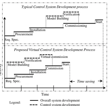
Commission
Time
Fig. 8. Time saving in virtual commissioning compared to typical commissioning
A
ct
iv
it
y
Proposed Virtual Control System Development Process
Start Verification
Model Building
Req. Spec. Procurement
Installation
Virtual commission
Time saving Typical Control System Development process
Commissioning Start
Req. Spec. Procurement
Installation
Verification Model Building
Overall system development Control system development Legend:
case of incidental processor overload. The whole virtual commissioing and interaction among different components are shown in fig. 7.
Simulink OPC toolbox offers a configuration block to specify OPC clients used in the model, to define the behavior of OPC error and events and to set the real-time behavior. During the simulation, the model executes in pseudo real-time, matching the system clock as closely as possible by automatically slowing the simulation. The block parameters can be configured so that the simulation runs more slowly than the system clock. By this process; processor and I/O related error can be easily identified.
Overall time and effort saving of virtual control system development compared to typical commissioning has shown in fig. 8. Yet, the rigorous testing system of virtual commissioning improves software fidelity by 47% without damaging physical equipment and reduces 75% of control system development time [1] by the application of virtual control system development and commissioning where 30 people worked with virtual commissioning and 30 test-people worked with non-virtual commissioning. Therefore, this virtual commissioning arrangement provides a better and efficient way of analyzing the fidelity of controller codes, evaluation of functional behavior in response to real time controller signals.
V. CONCLUSION
This paper introduces rapid control system development and virtual commissioning of a dynamic manufacturing system. It gives a clear methodology to develop control system from concept development to virtual implementation with less time and less effort. It is platform for integration of simulation environment and shop floor control so that control logic have been programmed, verified and validated in virtual environment before final execution. It promotes a generic platform that facilitates a wide range of application with significant benefits i.e. exchange of control requirement and design information among application
environment without human intervention; flow analysis and resource optimization; seamless control logic transfer to controller devices; logic verification, validation and collection of runtime data to calibrate control models.
REFERENCES
[1] G. Reinhart and G. Wunsch, "Economic application of virtual commissioning to mechatronic production systems," Prod. Eng. Res. Devel., vol. 1, pp. 371-379, 2007.
[2] P. Falkman, E. Helander and M. Andersson, "Automatic Generation : A way of ensuring PLC and HMI standards," in IEEE ETFA, 2011. [3] "3s-software," Codesys, [Online]. Available:
http://www.3s-software.com. [Accessed 26 12 12].
[4] "ISaGRAF," Rockwell Automation Company, [Online]. Available: http://www.isagraf.com. [Accessed 23 12 12].
[5] R. David, "Grafcet: a powerful tool for specification of logic controllers," IEEE Trans. on Control Systems Technology, vol. 3, no. 3, pp. 253-268, 1995.
[6] S. Klein, G. Frey and M. Minas, "PLC programming with signal interpreted Petri nets," Springer Verlag, vol. LNCS 2679, pp. 440-449, 2003.
[7] D. Thapa, D. Sin, J. Park and G. Wang, "Timed-MPSG: A Formal Model for Real Time Shop Floor Controller," IEEE Computer Society, CIMCA, pp. 101-101, 2006.
[8] K. Young, R. Piggin and P. Rachitrangsan, "An object-oriented approach to an agile manufacturing control system design," Int J Adv Manuf Technol, vol. 17, pp. 850-859, 2001.
[9] J. Han and K. H. Park, "Object-oriented ladder logic development framework based on the unified modeling language," Studies in Computational Intelligence, vol. 208, pp. 33-45, 2009.
[10] S. Rilling and G. Lochmann, "Physically Based Real-time Simulation of an Automation Plant," in Proceedings 25th European Conference on Modelling and Simulation , Krakow, Poland, 2011.
[11] Y. Cherner, A. Khan, A. Karim and G. Mullett, "Simulation-based Virtual and Hybrid Laboratories for Telecommunications Education," 2009.
[12] H. Xiaofeng, "Finite States Machine Models for Cell Control Code Generation," KTH, Stockholm, 2012.
[13] DEIF A/S, "From control design to PLC within minutes," DEIF Wind Power Technology, Frisenbogvej, Denmark, 2010.
Mosharraf Hossain is a PhD student
and received MSc in Production Engineering and Management in Department of Production Engineering at The Royal Institute of Technology. He received his B.Sc in Industrial and Production Engineering from Bangladesh University of Engineering and Technology in 2007.His research interests are modeling, simulation and automation of manufacturing system.
Daniel T. Semere, PhD, is currently an