Avaliação da confiabilidade e modo de
falha de coroas cerâmicas parafusadas a
implantes osseointegráveis de diferentes
conexões
Araçatuba
–
SP
2012
Tese apresentada à Faculdade de Odontologia do Câmpus de Araçatuba – UNESP para obtenção do Grau de Doutor em Odontologia – Área de Concentração em Prótese Dentária
Catalogação na Publicação (CIP)
Serviço Técnico de Biblioteca e Documentação – FOA / UNESP
Delben, Juliana Aparecida.
D344a Avaliação da confiabilidade e modo de falha de coroas cerâmicas parafusadas a implantes osseointegráveis de diferentes conexões / Juliana Aparecida Delben. - Araçatuba : [s.n.],
2012
164 f. : il. ; tab. + 1 CD-ROM
Tese (Doutorado) – Universidade Estadual Paulista, Faculdade de Odontologia de Araçatuba
Orientador: Prof. Dr. Wirley Gonçalves Assunção
1. Reabilitação bucal 2. Implantes dentários 3. Resistência de materiais 4. Biomecânica 5. Cerâmica
Dedicatória
A Deus
por me dar a vida e sempre iluminar os meus caminhos. Obrigada, Senhor, por tornar meus sonhos reais e por estar sempre ao meu lado. Te agradeço por todas as pessoas especiais que colocastes em minha vida pois foram um presente precioso para o meu crescimento. Agradeço também por todos os momentos de felicidade e ainda mais pelas dificuldades, quando pude então sentir o Seu imenso amor por mim.
À Nossa Senhora Aparecida
por interceder por mim junto a Deus desde o meu nascimento. Obrigada, minha Mãe do céu, por sua proteção diante dos desafios e por transformar minhas aflições em crescimento ao saber que posso contar com a sua intercessão.
Aos meus pais, Sueli e Ademir
por serem exemplos de amor incondicional, fé e luta. Não há palavra que possa expressar o meu imenso amor por vocês. Obrigada por abdicarem de seus sonhos para a realização dos meus e pela compreensão em todos os momentos da minha vida, mesmo em meus momentos de ausência. Tenho em vocês a minha fortaleza e a eterna gratidão por tudo que enfrentaram para se doarem completamente à nossa família. Obrigada por serem meus pais!
À minha irmã, Fabíola
também nos momentos de incertezas e dificuldades. Tenha certeza do meu imenso amor por você e do quanto sou feliz por ter me escolhido para ser sua irmãzinha.
À minha sobrinha e afilhada, Beatriz
Agradecimentos especiais
Ao meu orientador, Professor Wirley
Gonçalves Assunção
por ser um exemplo de professor e de ser humano para mim. Serei sempre grata pela confiança nos momentos de desafio, incentivo diante das incertezas e paciência quando o novo precisava ser desvendado. Tê-lo como meu orientador desde a minha iniciação científica representou não apenas um crescimento profissional por me espelhar em sua competência e dedicação, mas sim a conquista de uma amizade que me revelou valores importantes para toda a minha vida. Obrigada por me ensinar que nada somos se estivermos sozinhos e por acreditar nos meus ideais.
Aos
meus
co-orientadores
no
exterior,
Professor Nelson Renato França Alves da
Silva e Professora Simone Duarte
por proporcionarem uma experiência incrivelmente enriquecedora em minha vida. Tê-los como orientadores e amigos foi essencial para que eu trilhasse um caminho agradável e seguro durante o meu estágio de Doutorado no exterior. Agradeço por todo apoio, paciência, amizade e confiança. Tenham certeza do quanto são pessoas muito especiais em minha vida.
Ao Professor Van P. Thompson
pela acolhida no Departamento de Biomateriais e Biomimética da New York University – College of Dentistry. Obrigada pela confiança em mim depositada e pelo
Ao meu amigo Lucas Fernando Tabata
por ser um grande incentivador para que eu trilhasse a vida acadêmica. Tudo começou através de seu convite e hoje concretizo a realização de um sonho. Obrigada por me ajudar a descobrir a minha vocação e por nos proporcionar tantos momentos de alegria durante a nossa convivência. Tenha certeza do meu carinho por você e do quanto torço pela sua felicidade.
Ao meu amigo Valentim Adelino Ricardo Barão
por ser um exemplo de companheirismo, humildade e amizade sincera. Agradeço por todo o seu incentivo e carinho em todos os momentos. Sinto-me privilegiada por te conhecer e poder te chamar de amigo. Obrigada por me ensinar que os nossos sonhos valem à pena e que o nosso esforço e nossa fé em Deus são essenciais para atingirmos nossos ideais. Desejo que seja sempre muito feliz pois você é muito importante para mim.
À minha amiga Érica Alves Gomes
pela amizade e incentivo. Obrigada por seus conselhos e acolhida quando iniciei o meu caminho na pós-graduação. O seu exemplo de dedicação sempre foi muito importante para mim. Agradeço por todos os momentos de alegria que compartilhamos e desejo que a nossa amizade permaneça para sempre.
pela amizade e apoio para a realização desse trabalho. Obrigada pela oportunidade de conviver com você durante sua iniciação na vida acadêmica e compartilhar de seus anseios profissionais. Desejo que seus caminhos continuem iluminados para que você siga uma trajetória muito feliz.
Aos meus amigos Ana Carolina Hipólito,
Eduardo Faco, Juliana Jorge e Leonardo
Faverani
pela amizade, confiança e apoio. Obrigada pelos ótimos momentos de convivência e por permitirem que eu fizesse parte desta família. Desejo que os nossos caminhos continuem se encontrando em uma trajetória de realizações e amizade.
Aos
meus
amigos
Guilherme
Bonecker
Valverde,
Myrella
Castro,
Fabio
César
Lorenzoni,
Erika
Oliveira
de
Almeida,
Amilcar
Chagas
Freitas
Júnior,
Ramiro
Mendonça
Murata,
Vanessa
Pardi,
Livia
Rodrigues Perussi, Fernando Pozzi Semeghini
Guastaldi, Rodolfo Bruniera Anchieta, Lucas
Silveira Machado, Daniel Galera Bernabé,
Marcos Aurelio Benini Pascoal e Xi Wei
À Fundação de Amparo à Pesquisa do Estado
de São Paulo (FAPESP)
pela concessão da Bolsa de Doutorado e pelo apoio financeiro, indispensáveis para a realização deste trabalho.
À Coordenação de Aperfeiçoamento de Pessoal
de Nível Superior (CAPES)
Agradecimentos
À Faculdade de Odontologia de Araçatuba - UNESP pela oportunidade de
realização dos cursos de Graduação, Mestrado e Doutorado.
À New York University – College of Dentistry (NYUCD) pela oportunidade de
realização de estágio de Doutorado no exterior.
À coordenadora do Programa de Pós-Graduação em Odontologia, da Faculdade de
Odontologia de Araçatuba, da Universidade Estadual Paulista “Júlio de Mesquita Filho”, Profa. Adj. Dra. Maria José Hitomi Nagata pela competência e dedicação.
Aos Profs. Humberto Gennari Filho, Alício Rosalino Garcia, Cícero Eleutério da Silva Filho, Eulália Maria Martins da Silva, José Eduardo Rodrigues, Paulo Henrique dos Santos, Maria Cristina Rosifini Alves Rezende, Eduardo Passos Rocha, Débora Barros Barbosa, Paulo Renato Junqueira Zuim, Adriana Cristina Zavanelli, Marcelo Coelho Goiato, Eduardo Piza Pellizzer, Stefan Fiuza Carvalho Dekon, Renato Salviato Fajardo, Daniela Michelini dos Santos, Fellippo Ramos Verri, José Vitor Quinelli Mazaro, aos técnicos de laboratório Ana Lúcia Francischini Damaceno, Ana Marcelina dos Santos Bacaneli, Carlos Alberto Gonçalves, Eduardo Rodrigues Cobo, Jânder de Carvalho Inácio, Sérgio Augusto Feitosa e José Baleiero e aos demais funcionários do Departamento de Materiais
Às secretárias Maria Lúcia Bordan e Magda Requena Caciatore, do Departamento
de Materiais Odontológicos e Prótese da Faculdade de Odontologia de Araçatuba, da Universidade Estadual Paulista “Júlio de Mesquita Filho”, pela presteza e dedicação.
Aos Departamentos de Odontologia Infantil e Social e Odontologia Restauradora
da Faculdade de Odontologia de Araçatuba, da Universidade Estadual Paulista “Júlio de Mesquita Filho”, pela acolhida e concessão de utilização de equipamentos para a
realização deste trabalho.
Aos funcionários da Pós-graduação, pela paciência e disponibilidade.
Aos funcionários da Biblioteca da Faculdade de Odontologia de Araçatuba – UNESP pela disponibilidade e carinho.
Ao laboratório de prótese Romanini pela presteza e seriedade ao executarem a etapa
de confecção das coroas utilizadas no presente estudo.
Aos professores e funcionários do Departamento de Biomateriais e Biomimética e do Departamento de Ciências Básicas e Biologia Craniofacial da New York University – College of Dentistry pelo apoio e acolhida.
Aos professores George Quinn e Susanne Scherrer pelos ensinamentos em
Aos meus amigos e familiares por me apoiarem durante a minha jornada e
compreenderem os meus momentos de ausência.
Às minhas amigas Natália de Campos, Milene Martins Magosteiro e Marcela Pesci Peruzzo pelos anos de amizade e por toda paciência, incentivo e compreensão.
Ao meu cunhado Mateus Fiacadori Costa pelo incentivo e por sua alegria nos
momentos de descontração.
Aos meus amigos de graduação pela amizade, carinho e confiança.
Aos meus amigos de turma de doutorado Aldiéris Alves Pesqueira, Douglas Roberto Monteiro, Erika Oliveira de Almeida e Cristina Ramos pela convivência e amizade.
Um agradecimento especial ao amigo Aldiéris por tornar os nossos momentos sempre
mais prazerosos com sua alegria contagiante. Obrigada por suas palavras de carinho e por poder contar sempre com a sua ajuda. Desejo que seja muito feliz e que seus sonhos continuem se tornando realidade.
A todos os meus amigos de Pós-Graduação pela convivência e pelos momentos de
alegria.
À querida Helena por compartilhar comigo as suas alegrias de criança e por tornar os
Aos amigos Nagendran Ramalingam e Guilherme Nader por todos os momentos
prazerosos que compartilhamos. Obrigada por serem exemplos de humildade e amizade sincera. Tenham certeza de que a distância física não é capaz de diminuir o carinho que sinto por vocês.
Aos amigos Dindo, Satoshi, Arun, Trevor, Lukas, Kunal, Stephanie, Claudine, Smurti, Deepthi, Mary, Anupama, Shweta, Fatma, Raquel, Ellen, Julie, Linlin, Lela, Riddhi, Katie, Magdalena, Taisha e Vania pela amizade e troca de
Epígrafe
“
Tenho a impressão de ter sido uma criança brincando à beira-mar,
divertindo-me em descobrir uma pedrinha mais lisa ou uma concha mais
bonita que as outras, enquanto o imenso oceano da verdade continua
misterioso diante de meus olhos.
”
Delben JA. Avaliação da confiabilidade e modo de falha de coroas cerâmicas parafusadas a implantes osseointegráveis de diferentes conexões [tese]. Araçatuba: Faculdade de Odontologia de Araçatuba da Universidade Estadual Paulista; 2012.
Resumo Geral
Introdução: A performance de restaurações cerâmicas parafusadas a implantes com
diferentes conexões diante de fadiga é um fator importante para o sucesso do tratamento. Proposição: O objetivo do estudo foi avaliar a confiabilidade e o modo
de falha de coroas cerâmicas obtidas com pilares de zircônia parafusadas a implantes osseointegráveis de diferentes conexões. Material e método: Foram formados 3
grupos de acordo com as diferentes conexões pilar-implante: Grupo EH - hexágono externo, Grupo IH - hexágono interno e Grupo MT - Cone Morse. As coroas foram obtidas através da aplicação de cerâmica de revestimento sobre pilar de zircônia utilizando a técnica de aplicação em camadas e parafusadas aos implantes com parafusos de retenção específicos para cada sistema. Os espécimes foram submetidos ao teste de fadiga acelerado step-stress de acordo com os perfis leve (n=9), moderado (n=6) e agressivo (n=3) determinados após teste de resistência à fratura (n=4) em máquina de ensaio universal. Os dados foram inicialmente avaliados pela análise de use level probability Weibull. Os valores e intervalos de confiabilidade foram obtidos através de standard probability calculation. Considerando os valores de carga para a falha dos espécimes, foi calculada a distribuição de Weibull. Análise fractográfica foi conduzida através de estereomicroscopia e microscopia eletrônica de varredura.
Resultado: O valor de β de todos os grupos (EH-β= 0,6307; IH-β=0,9730;
MT-β=0,1942) sugere que as falhas foram mais associadas ao nível de carga do que ao
grupo MT com diferença estatisticamente significante entre si. Já para uma missão de 50.000 ciclos e carga de 200 N, os valores de confiabilidade foram de 100% para o grupo EH, 98% para o grupo IH e 89% para o grupo MT. Nesse caso, não houve diferença estatisticamente significante entre os grupos EH e IH e entre os grupos IH e MT. A distribuição de Weibull revelou valores decrescentes de β e η para os grupos EH (β=13,05/η=561,81), IH (β=5,81/η=513,45) e MT (β=5,31/η=333,23) com
diferença estatisticamente significante entre si. As falhas mais frequentes no grupo EH foram falha coesiva da cerâmica de revestimento, falha adesiva na interface cerâmica/pilar e fratura na região do hexágono do pilar. Alguns espécimes também apresentaram deformação e/ou fratura na região do hexágono do implante. No grupo IH foi observado falha coesiva da cerâmica de revestimento próxima ao ponto de carregamento palatino, fratura do pilar característica de branching crack e falha adesiva entre Y-TZP e titânio no hexágono do pilar. Já para o grupo MT, observou-se fratura na região do pescoço do pilar além de fratura e flexão do parafuso de retenção.
Conclusão: A conexão pilar-implante influenciou a confiabilidade e o modo de falha
das restaurações. As vantagens e limitações de cada sistema devem ser avaliadas para correta indicação clínica.
Delben JA. Evaluation of reliability and failure mode of screw-retained all-ceramic crowns attached to osseointegrated implants with different connections [thesis]. Araçatuba: Araçatuba Dental School of São Paulo State University; 2012.
General Abstract
Introduction: The performance of screw-retained all-ceramic crowns attached to
implants with different connections under fatigue is a relevant factor for treatment success. Purpose: The aim of this study was to evaluate the reliability and failure
mode of screw-retained all-ceramic crowns fabricated with zirconia abutments attached to osseointegrated implants with different connections. Material and method: Three groups were designed according to the implant-abutment connection:
Group EH - external hexagon, Group IH - internal hexagon and Group MT - Morse taper. Layering technique was used for veneering of zirconia abutments. The crowns were attached to the implants with the retention screws of each system. Step-stress accelerated fatigue test was conducted according to mild (n=9), moderate (n=6) and aggressive (n=3) profiles determined after single-load-to-fracture test (n=4) in a universal testing machine. Data was previously analyzed by use level probability Weibull. Standard probability calculation was used to determine the reliability and confidence bounds. Weibull distribution was calculated based on the load to failure. Failure modes were described under light polarized microscopy and scanning electron microscopy. Result: β of all groups (EH-β= 0.6307; IH-β=0.9730; MT-β=0.1942)
was no significant difference between EH and IH and between IH and MT. Weibull distribution revealed descending β and η for the groups EH (β=13.05/η=561.81), IH (β=5.81/η=513.45) and MT (β=5.31/η=333.23) and significant difference between the
groups. Group EH showed veneer cohesive failure, adhesive failure at veneer/abutment interface and abutment hexagon fracture. Some samples also exhibited deformation and/or fracture of implant hexagon. Group IH presented veneer cohesive failure near to the loading area, abutment branching crack and adhesive failure between Y-TZP and titanium insert at the abutment hexagon. For group MT, it was observed fracture at abutment neck and fracture/bending of the retention screw.
Conclusion: Abutment-implant connection influenced the reliability and failure mode
of restorations. The advantages and limitations of each system should be carefully evaluated for clinical indication.
Lista de Figuras
Figures
Figure 1 - Longitudinal section of crown/abutment-retention screw-implant systems...64
Figure 2 - Profiles of step-stress accelerated fatigue testing...65
Figure 3 - Weibull 2-parameter contour plot (Weibull modulus vs characteristic strength)...66
Figure 4 - Failure mode of group EH. A) Arrows indicate fracture of veneer and abutment hexagon. B) Veneer fragment. Dashed line represents abutment edge. Hackle lines and wake hackles reveal crack propagation from abutment/veneer interface to veneer. C) Hackle lines demonstrate crack propagation from hexagon vertex. D) Arrows indicate implant hexagon fracture...67
Figure 5 - Failure mode of group IH. A) Abutment branching crack and veneer fracture near to loading area. B) Adhesive failure at Y-TZP/Ti interface in abutment connecting region. C) Wake hackles demonstrate crack propagation in abutment from loading area. D) Arrows indicate porosities on abutment surface. Dashed line highlights gap at abutment/veneer interface...68
platform and remaining abutment. C) and D) Compression curl at abutment buccal surface and twist hackles demonstrate abutment crack propagation from palatal to buccal surface...69
Anexo
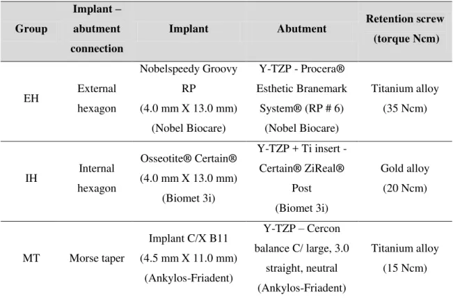
Figura 1 - Imagem do implante e pilar Nobel Biocare caracterizando a conexão de hexágono externo do grupo EH...94
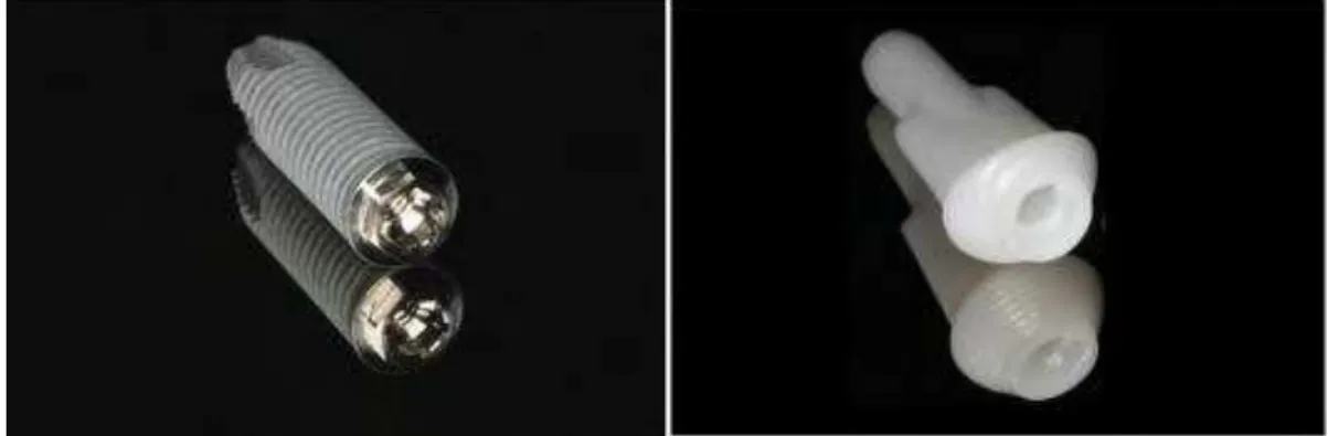
Figura 2 - Imagem do implante e pilar Biomet 3i caracterizando a conexão de hexágono interno do grupo IH...95
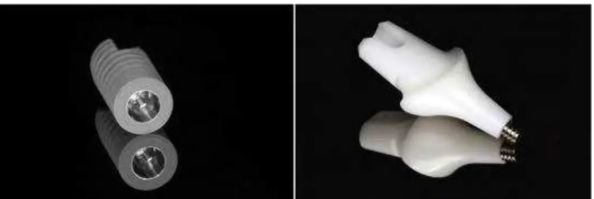
Figura 3 - Imagem do implante e pilar Ankylos-Friadent caracterizando a conexão Cone Morse do grupo MT...95
Figura 4 - Secção longitudinal dos sistemas coroa/pilar-parafuso de retenção-implante...95
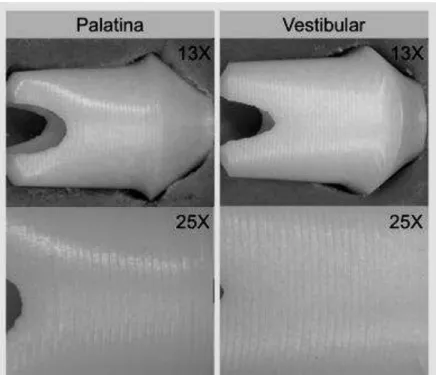
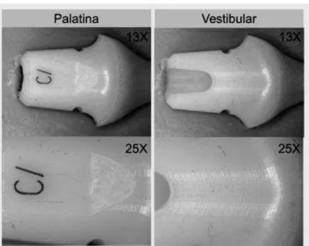
Figura 5 - Imagem dos pilares Nobel Biocare obtidas em estereomicroscopia em aumento de 13X e 25X...97
Figura 6 - Imagem dos pilares Biomet 3i obtidas em estereomicroscopia em aumento de 13X e 25X………...97
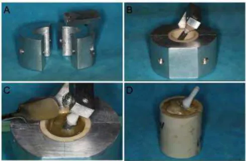
Figura 8 - Embutimento do implante: A) Matriz metálica bipartida, B) Posicionamento do implante a uma inclinação de 30°, C) Inserção da resina de poliéster modificado, D) Aspecto final do espécime após embutimento do implante...99
Figura 9 - Coroas obtidas após aplicação da cerâmica de revestimento sobre o pilar de zircônia dos grupos EH, IH e MT...100
Figura 10 - Procedimentos para fechamento da cavidade de acesso ao parafuso de retenção: A) inserção de politetrafluoretileno, B) inserção de resina composta, C) polimerização da resina composta, D) aspecto final da face palatina da coroa...101
Figura 11 - Aplicação de carga compressiva na face palatina da coroa posicionada na máquina de ensaios universal...102
Figura 12 - Espécime do grupo EH em análise de estereomicroscopia. Fratura do pilar e da cerâmica de revestimento no plano sagital...103
Figura 13 - Espécime do grupo IH em análise de estereomicroscopia. Setas indicam a linha de fratura ocorrida no pilar de zircônia...103
Figura 15 - Perfis do teste de fadiga acelerado step-stress...106
Figura 16 - Espécime posicionado para carregamento na face palatina durante teste de fadiga acelerado...109
Figura 17 - Curva de probabilidade de Weibull do grupo EH...113
Figura 18 - Curva de probabilidade de Weibull do grupo IH...113
Figura 19 - Curva de probabilidade de Weibull do grupo MT...113
Figura 20 – Simple plot (confiabilidade X carga) da distribuição de Weibull dos grupos...117
Figura 21 - Contour plot da distribuição de Weibull dos grupos...117
Figura 23 - Fragmento de fratura da cerâmica de revestimento. A linha tracejada representa o contorno do pilar reproduzido na cerâmica de revestimento (região superior corresponde ao ápice incisal). As setas indicam a propagação da falha a partir do pilar em direção à cerâmica de revestimento baseada na configuração das hackle lines e wake hackles...120
Figura 24 - Fragmento de fratura na região do hexágono do pilar. A configuração das arrest lines e hackle lines revela a propagação da falha a partir da região do vértice do hexágono do pilar...121
Figura 25 - A área em destaque revela a descontinuidade na estrutura interna do material na região do vértice do hexágono do pilar...121
Figura 26 - Caracterização da falha dos espécimes do grupo IH em estereomicroscopia: A) Face palatina. As áreas em destaque revelam os pontos de interesse da análise fractográfica demonstrados na sequência, B) A fratura do pilar característica de branching crack revela a origem da fratura a partir do ponto de carregamento. A configuração das hackle lines na cerâmica de revestimento demonstra que a falha propagou-se a partir do pilar para a cerâmica de revestimento na região de carregamento palatino, C) Hackle lines na porção média do pilar demonstram a propagação da falha em direção à região cervical do pilar. Há também presença de trinca na superfície vestibular do pilar, D) A configuração das hackle
Figura 27 - A) Região de carregamento palatino. Interfaces entre resina composta utilizada para fechamento da cavidade de acesso ao parafuso de retenção, pilar e cerâmica de revestimento, B) Fragmento de fratura do pilar. Canto superior esquerdo da foto corresponde à região de carregamento palatino. A configuração das wake hackles revela a direção de propagação da falha no pilar a partir do ponto de
carregamento, C) Lado esquerdo da foto corresponde à região de carregamento palatino. A configuração de twist hackles e wake hackles revela a direção de propagação da falha na cerâmica de revestimento a partir do pilar...124
Figura 28 - A área tracejada evidencia o gap presente na interface cerâmica/pilar. As setas indicam porosidade na superfície do pilar...125
Figura 30 - Fragmento de fratura do pilar. Lado superior da foto corresponde à face vestibular: A) A configuração das twist hackles e compression curl evidencia a direção de propagação da fratura a partir da face palatina do pilar, B) A seta branca indica a origem da fratura do pilar...128
Lista de Tabelas
Tables
Table 1 - Characteristics of implant-abutment connection, implant, abutment and retention screw...61
Table 2 - Calculated reliability and upper and lower limits of groups EH, IH and MT...62
Anexo
Tabela 1 - Características dos sistemas (implante, pilar e parafuso de retenção) utilizados nos diferentes grupos...94
Tabela 2 - Média (±DP) da carga máxima de resistência à fratura (N) dos grupos...111
Tabela 3 - Características do perfil leve...107
Tabela 4 - Características do perfil moderado...107
Tabela 5 - Características do perfil agressivo...108
Tabela 7 - Valores de confiabilidade e intervalo de confiança dos grupos para uma missão de 50.000 ciclos e carga de 400 N...115
Tabela 8 - Valores de confiabilidade e intervalo de confiança dos grupos para uma missão de 50.000 ciclos e carga de 200 N...115
Lista de Abreviaturas
CAD/CAM = CET = cm =
oC =
GPa =
Computer-assisted design/computer-assisted manufacturing
Coeficiente de expansão térmica Centímetro Grau Celsius Gigapascal Hz = min = Hertz Minuto mm = mol = MPa = Milímetro Molécula-grama Megapascal
N = Newton
Ncm = SEM =
Newton centímetro
Scanning electron microscopy SSALT =
Y-TZP =
Step-stress accelerated life testing
Sumário
1 Introdução (Introduction) 30
2 Proposição (Purpose) 34
3 Material e Método (Material and Method) 36
4 Resultado (Result) 40
5 Discussão (Discussion) 43
6 Referências (References) 51
30
Introduction
iBalance between biological, esthetic and mechanical factors dictates the success of implant-supported restorations, especially in single maxillary anterior crowns (Doring et al. 2004). In this sense, implant design has evolved to fulfill biomechanical requirements, resulting in different implant-abutment connections (Cehreli et al. 2004) and restorations systems (Blatz et al. 2009, Gomes & Montero 2011).
In general, the implant-abutment interface can be classified into internal and external joints exhibiting butt-joint connections or conical connections. This interface may be further classified according to the presence of a lock against rotation at the implant-abutment complex (Dittmer et al. 2012, Dittmer et al. 2011).
Although the external hexagon connection presents anti-rotational mechanism and compatibility among different systems, the short index and higher center of rotation lead to lower resistance for rotational and lateral movements (Maeda et al. 2006). In contrast, several studies (Bernardes et al. 2009, Dittmer et al. 2011, Maeda et al. 2006, Mangano et al. 2009, Steinebrunner et al. 2008) demonstrated that internal connections provide better biological sealing, joint stability, stress distribution and resistance to bending moments as a result of deeper and greater joining walls. However, the thinner lateral fixture wall at the connecting part may lead to high stress concentration and abutment/implant failure (Cehreli et al. 2004, Dittmer et al. 2011, Freitas et al. 2012, Maeda et al. 2006).
Within the restoration systems, ceramic implant abutments have been introduced to reduce the risk of gray or blue discolorations of the surrounding soft tissues, especially in patients with a thin gingival biotype (Blatz et al. 2009, Yildirim
et al. 2003). In this sense, zirconium oxide abutments (Adatia et al. 2009, Aramouni et al. 2008, Garine et al. 2007, Gomes & Montero 2011) have been commonly used because of its high flexural strength, fracture toughness, low thermal conductivity, low corrosion potential, biocompatibility, and favorable interaction with soft and hard tissues (Aboushelib et al. 2008, Baldassarri et al. 2012, Pittayachawan et al. 2007). However, zirconia may also exhibit failures as a result of low temperature degradation intrinsic to the material (Guess et al. 2010b, Lughi & Sergo 2010) and limited bond strength with the veneering ceramic (Aboushelib et al. 2008, Fischer et al. 2008, Fischer et al. 2009, Komine et al. 2012, Mosharraf et al. 2011). Clinical trials and in vitro studies reported that abutment fracture, cohesive failure of the veneering ceramic and adhesive failure at zirconia-veneer interface are common complications with ceramic restorations on zirconia structure (Al-Amleh et al. 2010, Baldassarri et al. 2011, Ekfeldt et al. 2011, Guess et al. 2008, Komine et al. 2012, Mosharraf et al. 2011).
The mechanical performance of zirconia abutments with different implant-abutment connections and veneering systems has been demonstrated by several authors (Adatia et al. 2009, Apicella et al. 2011, Att et al. 2006, Butz et al. 2005, Nguyen et al. 2009a, Nothdurft et al. 2011, Park et al. 2012, Sailer et al. 2009, Truninger et al. 2012, Yildirim et al. 2003). However, the results are usually based upon either static loading until failure or fatigue tests that do not reproduce loading conditions to cause the system fatigue in a timely manner. To solve this limitation, few studies have applied the step-stress accelerated life testing (SSALT) for reliability
evaluation of implants (Baldassarri et al. 2011, Freitas et al. 2012, Martins et al. 2012,
Mitsias et al. 2010) and ceramic systems (Bonfante et al. 2010a, Coelho et al. 2009b).
32
than clinical conditions within a short time span so that failure is accelerated and specimens can be analyzed in a reasonable time period (Baldassarri et al. 2011). The behavior of the samples at accelerated stress is used to reveal the failure behavior of
the specimens at use stresses (Bonfante et al. 2010b). However, comparison of
screw-retained ceramic restorations on zirconia abutments with different implant-abutment
34
Purpose
The aim of this study was to evaluate the reliability and failure mode of screw-retained all-ceramic crowns fabricated with zirconia abutments attached to implants with different connections.
36
Material and Method
Study design
Three implant-abutment connection designs were evaluated in this study and divided into the groups (n=22): EH (external hexagon system - Nobel Biocare, Goteborg, Sweden), IH (internal hexagon system - Biomet 3i, Palm Beach Gardens, FL, USA), and MT (Morse taper system - Ankylos - Friadent, Mannheim, Germany).
The dimensions and characteristics of components are shown in table 1 and figure 1. All abutments and implants were previously evaluated in stereomicroscopy (SteREO Discovery V20, Carl Zeiss MicroImaging GmbH, Jena, Germany) to check any deformation/crack on component surface and connecting area.
Samples preparation
All implants were embedded in modified polyester autopolymerizing resin (Technovit 4000, Heraues Kulzer, Wehrheim, Germany) at 30o to the horizontal plane according to the ISO 14801:2007 (Dynamic fatigue test for endosseous dental implants). The resin has a modulus of elasticity of approximately 12 GPa, which
approximates that of human bone (Att et al. 2006).
Maxillary central incisors crowns (11.0 mm in height, 8.0 mm proximally) (Att et al. 2006) were fabricated with the nano-fluorapatite ceramic IPS e.max Ceram (Ivoclar Vivadent, Liechtenstein, Swiss) layered on the zirconia abutments according to the manufacturer’s instructions for firing temperature (750°C) and cycles (furnace
Programat EP500, Ivoclar Vivadent). Clear ceramic was veneered for better visualization of flaws/cracks during testing. After polishing and finishing, e.max Ceram glaze was applied according to the manufacturer’s instructions (Ivoclar
The retention screws were tightened using a torque gauge (BTG36CN-S, Tohnichi MFG. CO. Ltd, Tokyo, Japan) according to the torque recommended by each manufacturer (table 1). After 3 minutes, the screws were retightened to avoid peload loss as demonstrated in previous studies (Assuncao et al. 2012, Delben et al. 2011, Kano et al. 2006). The screw access channel was restored with polytetrafluoroethylene and composite resin (Z-250, 3M ESPE, St. Louis, MN, USA).
Mechanical testing and reliability analysis
Four specimens of each group underwent single load-to-failure (SLF) testing at
cross-head speed of 1 mm/min in a universal testing machine (INSTRON 5666,
Canton, MA, USA) with a flat tungsten-carbide indenter applying the load 3.0 mm
below the incisal edge of the crown. Based upon the mean load-to-failure, three
step-stress accelerated life testing (SSALT) profiles (figure 2) were assigned to mild (n=9),
moderate (n=6), and aggressive (n=3) fatigue profiles (ratio 3:2:1, respectively)
(Bonfante et al. 2010a, Freitas et al. 2011). These profiles are named based on the
load increase in which a specimen is fatigued to reach a certain level of load. It means
that specimens assigned to a mild profile will be cycled longer to reach the same load
of a specimen assigned to either moderate or aggressive profiles. The fatigue testing
was conducted under water at 10 Hz using an electrodynamic fatigue testing machine
(ELF 3300, EnduraTec Division, Bose Corporation, Minnetonka, MN, USA) with a
tungsten-carbide indenter applying the load 3.0 mm below the incisal edge of the
crown (Adatia et al. 2009, Att et al. 2006, Butz et al. 2005).
Fatigue testing was performed until failure (fracture of the veneer, bending or
fracture of the abutment) or survival (no failure occurred at the end of the step-stress
38
the indenter surpassed the lower limit of the sample being tested (standardized in
about 1.5 mm), where the machine automatically halted testing.
Based upon the step-stress distribution of failures, use level probability Weibull
curves (probability of failure vs cycles) were calculated (Alta Pro 7, ReliaSoft,
Tucson, AZ, USA) using power law relationship for damage accumulation. Reliability
for a mission of 50,000 cycles at 400 N and 200 N (90% two-sided confidence
interval) was calculated for comparison between the groups. Weibull 2-parameter
plots were generated based on Weibull modulus and characteristic strength.
Failure mode analysis
All samples were inspected under polarized light microscopy (MZ-APO
stereomicroscope, Carl Zeiss MicroImaging, Thornwood, NY, USA) for failure mode
classification and comparison between the groups. The most representative failed
samples of each group were gold sputtered (Emitech K650, Emitech Products Inc.,
Houston, TX, USA) and further observed using a scanning electron microscope
40
Result
SLF and reliability
The mean ± SD SLF was 646.07 ± 77.78 N for group EH, 464.35 ± 119.10 N
for group IH, and 429.65 ± 29.87 N for group MT.
The use level probability Weibull plots at use stress of 400 N and 90%
confidence interval revealed β (Weibull shape factor) of 0.6307 for group EH, 0.9730 for group IH and 0.1942 for group MT. In this sense, β < 1 demonstrated that strength was the main factor dictating the behavior of all groups instead of damage
accumulation.
The calculated reliability (two-sided 90% confidence intervals) for a mission of
50,000 cycles at 400 N was 97% for group EH, 46% for group IH and 0.5% for group
MT. No overlap between the upper and lower limits represented statistically significant difference between the groups (table 2). For a mission of 50,000 cycles at 200 N, the calculated reliability (two-sided 90% confidence intervals) increased for
100% for group EH, 98% for group IH and 89% for group MT. Overlapped upper and lower limits revealed no significant difference between the groups EH and IH and between IH and MT (table 2).
Assuming that fatigue played little or no role in failure, data were plotted
according to the load at failure as a Weibull distribution (Weibull 7++, Reliasoft) for
Failure mode
The predominant failure mode observed in the group EH (figure 4) was cohesive failure of veneering porcelain associated to adhesive failure at zirconia-veneer interface and abutment fracture at connecting region. Some samples also exhibited fracture of implant hexagon. SEM revealed wake hackles and hackle lines that dictate fracture propagation from the abutment to the veneering at the loading area. Fractographic analysis also revealed that abutment fracture at connecting region originated from the hexagon vertex.
In the group IH (figure 5), the predominant failure mode was cohesive failure of veneering porcelain at the loading area, abutment fracture characterizing branching crack and adhesive failure between zirconia and titanium insert at abutment connecting part. SEM confirmed the abutment fracture origin at the loading area. It was also observed gap at abutment-veneer interface and porosities on abutment surface.
Discussion
The null hypothesis was rejected since there was difference on reliability and failure mode between the abutment-implant systems evaluated.
According to the use level probability Weibull of all groups, damage accumulation was not the most important factor for failure. In this analysis, β (Weibull shape factor) describes failure rate changes over time (β
decreasing over time, commonly associated with “early failures” or failures that occur
because of egregious flaws; β ~1: failure rate that does not vary over time, associated with failures of a random nature; β > 1: failure rate is increasing over time, associated with failures related to damage accumulation) (Bonfante et al. 2010b). Considering
that all groups were restored with similar materials (titanium implant and layered
zirconia abutment), it can be assumed that other characteristics (flexural strength,
fracture toughness, joint stability, fracture resistance) of the implant-supported
restoration than fatigue influence the system performance. It is important to highlight
that, although the accelerated fatigue testing was conducted under water, the short
time span may not be enough to simulate the clinical low temperature degradation
experienced by zirconia, which could reduce flexural strength and increase the risk to
catastrophic failure (Guess et al. 2010a, Lughi & Sergo 2010).
44
2011), it can be extrapolated that all abutment-implant systems would present appropriate performance in a clinical scenario. Although the Morse taper connection presented the lowest calculated reliability in both conditions (200 N and 400 N), clinical trials (Doring et al. 2004, Mangano & Bartolucci 2001, Mangano et al. 2009) revealed that implant-supported restorations with this interface design present appropriate mechanical stability and clinical performance.
Descending Weibull modulus was observed at Weibull distribution of the groups EH (β=13.05), IH (β=5.81) and MT (β=5.31), respectively. The Weibull modulus is a shape parameter for the Weibull distribution model that maps the probability of failure of a component at varying stresses. The higher the calculated Weibull modulus, the lower the measurement variation among the samples of a group (Klein 2009). In this sense, the higher Weibull modulus of group EH confirmed that failure was more uniformly distributed throughout the fatigue testing profiles in comparison to the groups IH and MT. This result may also suggest that external hexagon connections present more predictable behavior in comparison to the other connections within the conditions of this study.
connecting joint design (Balfour & O'Brien 1995, Bernardes et al. 2009, Dittmer et al. 2012, Dittmer et al. 2011, Maeda et al. 2006, Mangano et al. 2009, Merz et al. 2000, Norton 2000, Steinebrunner et al. 2008). However, in a strain gauge analysis, it was not observed reduced strain in internal connections compared to external interface (Nishioka et al. 2011). In addition, some authors observed that the thinner lateral fixture wall at the connecting part of Morse taper system is more prone to abutment/implant fracture (Dittmer et al. 2011, Freitas-Junior et al. 2012) due to higher stress concentration (Cehreli et al. 2004, Pessoa et al. 2010).
Furthermore, the failure mode is an important additional data for predicting treatment success. The compression curl observed at fractrographic analysis of MT samples suggested that the abutment fracture resulted from flexural failure (Scherrer et al. 2008) at the thinnest abutment region. Despite a high elastic modulus (215 GPa) and flexure strength (1,000 MPa), zirconia cannot be used in thin sections due to its
characteristic brittleness (Aboushelib & Salameh 2009). Although retrievability is an
advantageous feature of screw-retained restorations for prosthesis repair (Albrecht et
al. 2011, Guess et al. 2010a), abutment neck fracture in a Morse taper connection is a
challenging clinical scenario since joint friction hampers removal of remaining
abutment fragment at cervical region. In addition, removal of the screw fragment
from implant internal threads is a tough complication for this type of restoration
connected with a single screw and no intermediate component.
The cohesive failure within veneering porcelain observed in EH and IH samples
is a common failure reported for ceramic restorations with zirconia framework
(Baldassarri et al. 2011, Ekfeldt et al. 2011, Fischer et al. 2008). Veneer fracture is a
consequence of restoration geometry, veneering thickness and mechanical
46
sense, some authors (Fischer et al. 2008) suggested that to realize the benefit of high
strength of zirconia frameworks, the strength of veneering ceramics has to be
improved. The cohesive failure of veneering porcelain was associated to adhesive
failure at abutment-veneer interface since sufficient bond strength between the
veneering ceramic and the framework is a concern for long-term success of zirconia
restorations (Fischer et al. 2008, Guess et al. 2008, Mosharraf et al. 2011). Although
the layering porcelain used in this study (IPS e.max Ceram) presents a slightly lower CTE than that of the zirconia abutment to ensure sufficient bond strength (Komine et al. 2012), this characteristic is also influenced by chemical bonds, mechanical interlocking, type and concentration of defects at the interface, and wetting properties
(Fischer et al. 2008, Fischer et al. 2009, Mosharraf et al. 2011). In addition, the
implant hexagon fracture/deformation observed in some EH samples was also
reported in a previous study as a consequence of higher hardness of zirconia abutment
in comparison to implant titanium platform (Nguyen et al. 2009a). Clinically, implant
hexagon fracture/deformation is a tough scenario since it cannot be repaired and
would probably require implant removal. However, the implant hexagon fracture may
result from the worst-case scenario simulated with implant embedment at 30o as
dictated by the ISO 14801:2007, which indicates that treatment planning should
provide stress transferring towards the system long axis.
In the group IH, the abutment fracture characterizing branching crack suggested
that failure originated from the loading area. In screw-retained restorations, the screw
abutments is a common failure reported in previous studies (Att et al. 2006, Nguyen et al. 2009a, Sailer et al. 2009, Truninger et al. 2012) using abutments with metallic insert for internal connection systems. In these abutments, zirconia is sintered onto a titanium insert that fits to the implant internal hexagon and this basal reinforcement may contribute to increased fracture resistance (Butz et al. 2005). Clinically, separation of zirconia from the internal insert may act as a protective mechanism for the implant platform since zirconia fracture will occur earlier and away from the prime connecting region. However, it must be observed that this two-piece abutment could lead to implant failure by plastic deformation while a one-piece ceramic abutment would fracture earlier, preserving the implant itself intact (Truninger et al. 2012).
Based on the findings of the present study it can be assumed that implant-abutment connection influenced reliability and failure mode of restorations but
damage accumulation was not an accelerator of samples failure. Although all groups
exhibited characteristic strength higher than mean functional anterior region load,
Acknowledgements
To Department of Biomaterials and Biomimetics of New York
University-College of Dentistry, The State of São Paulo Research Foundation (FAPESP) for
financial support, and Laboratory Romanini (Brazil) for support on crowns
References
iiAboushelib, M. N., Kleverlaan, C. J. & Feilzer, A. J. (2008) Effect of zirconia type on its bond strength with different veneer ceramics. Journal of Prosthodontics 17:
401-408.
Aboushelib, M. N. & Salameh, Z. (2009) Zirconia implant abutment fracture: Clinical case reports and precautions for use. International Journal of Prosthodontics 22:
616-619.
Adatia, N. D., Bayne, S. C., Cooper, L. F. & Thompson, J. Y. (2009) Fracture resistance of yttria-stabilized zirconia dental implant abutments. Journal of Prosthodontics 18: 17-22.
Albrecht, T., Kirsten, A., Kappert, H. F. & Fischer, H. (2011) Fracture load of different crown systems on zirconia implant abutments. Dental Materials 27:
298-303.
Apicella, D., Veltri, M., Balleri, P., Apicella, A. & Ferrari, M. (2011) Influence of abutment material on the fracture strength and failure modes of abutment-fixture assemblies when loaded in a bio-faithful simulation. Clinical Oral Implants Research
22: 182-188.
52
Att, W., Kurun, S., Gerds, T. & Strub, J. R. (2006) Fracture resistance of single-tooth implant-supported all-ceramic restorations after exposure to the artificial mouth. Journal of Oral Rehabilitation 33: 380-386.
Baldassarri, M., Zhang, Y., Thompson, V. P., Rekow, E. D. & Stappert, C. F. (2011) Reliability and failure modes of implant-supported zirconium-oxide fixed dental prostheses related to veneering techniques. Journal of Dentistry 39: 489-498.
Baldassarri, M., Hjerppe, J., Romeo, D., Fickl, S., Thompson, V. P. & Stappert, C. F. (2012) Marginal accuracy of three implant-ceramic abutment configurations. International Journal of Oral & Maxillofacial Implants 27: 537-543.
Balfour, A. & O'Brien, G. R. (1995) Comparative study of antirotational single tooth abutments. Journal of Prosthetic Dentistry 73: 36-43.
Blatz, M. B., Bergler, M., Holst, S. & Block, M. S. (2009) Zirconia abutments for single-tooth implants--rationale and clinical guidelines. Journal of Oral and Maxillofacial Surgery 67: 74-81.
Bonfante, E. A., Coelho, P. G., Guess, P. C., Thompson, V. P. & Silva, N. R. (2010a) Fatigue and damage accumulation of veneer porcelain pressed on y-tzp. Journal of Dentistry 38: 318-324.
implant-supported y-tzp and mcr three-unit bridges. Clinical Implant Dentistry and Related Research 12: 235-243.
Butz, F., Heydecke, G., Okutan, M. & Strub, J. R. (2005) Survival rate, fracture strength and failure mode of ceramic implant abutments after chewing simulation. Journal of Oral Rehabilitation 32: 838-843.
Cehreli, M. C., Akca, K. & Iplikcioglu, H. (2004) Force transmission of one- and two-piece morse-taper oral implants: A nonlinear finite element analysis. Clinical Oral Implants Research 15: 481-489.
Coelho, P. G., Silva, N. R., Bonfante, E. A., Guess, P. C., Rekow, E. D. & Thompson, V. P. (2009b) Fatigue testing of two porcelain-zirconia all-ceramic crown systems. Dental Materials 25: 1122-1127.
Dittmer, M. P., Dittmer, S., Borchers, L., Kohorst, P. & Stiesch, M. (2012) Influence of the interface design on the yield force of the implant-abutment complex before and after cyclic mechanical loading. Journal of Prosthodontic Research 56: 19-24.
54
Doring, K., Eisenmann, E. & Stiller, M. (2004) Functional and esthetic considerations for single-tooth ankylos implant-crowns: 8 years of clinical performance. Journal of Oral Implantology 30: 198-209.
Ekfeldt, A., Furst, B. & Carlsson, G. E. (2011) Zirconia abutments for single-tooth implant restorations: A retrospective and clinical follow-up study. Clinical Oral Implants Research 22: 1308-1314.
Fischer, J., Grohmann, P. & Stawarczyk, B. (2008) Effect of zirconia surface treatments on the shear strength of zirconia/veneering ceramic composites. Dental Materials J 27: 448-454.
Fischer, J., Stawarzcyk, B., Trottmann, A. & Hammerle, C. H. (2009) Impact of thermal misfit on shear strength of veneering ceramic/zirconia composites. Dental Materials 25: 419-423.
Freitas, A. C., Jr., Bonfante, E. A., Rocha, E. P., Silva, N. R., Marotta, L. & Coelho, P. G. (2011) Effect of implant connection and restoration design (screwed vs. Cemented) in reliability and failure modes of anterior crowns. European Journal of Oral Sciences 119: 323-330.
Freitas-Junior, A. C., Almeida, E. O., Bonfante, E. A., Silva, N. R. & Coelho, P. G. (2012) Reliability and failure modes of internal conical dental implant connections. Clinical Oral Implants Research doi: 10.1111/j.1600-0501.2012.02443.x.
Guess, P. C., Kulis, A., Witkowski, S., Wolkewitz, M., Zhang, Y. & Strub, J. R. (2008) Shear bond strengths between different zirconia cores and veneering ceramics and their susceptibility to thermocycling. Dental Materials 24: 1556-1567.
Guess PC, Att W, Strub JR (2010a). Zirconia in Fixed Implant Prosthodontics.
Clinical Implant Dentistry and Related Research 14: 633-645.
Guess, P. C., Zhang, Y., Kim, J. W., Rekow, E. D. & Thompson, V. P. (2010b) Damage and reliability of y-tzp after cementation surface treatment. Journal of Dental Research 89: 592-596.
Klein, C. A. (2009) Characteristic strength, weibull modulus, and failure probability of fused silica glass. Optical Engineering 48.
Lughi, V. & Sergo, V. (2010) Low temperature degradation -aging- of zirconia: A critical review of the relevant aspects in dentistry. Dental Materials 26: 807-820.
56
Mangano, C. & Bartolucci, E. G. (2001) Single tooth replacement by morse taper connection implants: A retrospective study of 80 implants. International Journal of Oral & Maxillofacial Implants 16: 675-680.
Mangano, C., Mangano, F., Piattelli, A., Iezzi, G., Mangano, A. & La Colla, L. (2009) Prospective clinical evaluation of 1920 morse taper connection implants: Results after 4 years of functional loading. Clinical Oral Implants Research 20: 254-261.
Martins, L. M., Bonfante, E. A., Zavanelli, R. A., Freitas, A. C., Jr., Silva, N. R., Marotta, L. & Coelho, P. G. (2012) Fatigue reliability of 3 single-unit implant-abutment designs. Implant Dentistry 21: 67-71.
Merz, B. R., Hunenbart, S. & Belser, U. C. (2000) Mechanics of the implant-abutment connection: An 8-degree taper compared to a butt joint connection. International Journal of Oral & Maxillofacial Implants 15: 519-526.
Mitsias, M. E., Silva, N. R., Pines, M., Stappert, C. & Thompson, V. P. (2010) Reliability and fatigue damage modes of zirconia and titanium abutments. International Journal of Prosthodontics 23: 56-59.
Nguyen, H. Q., Tan, K. B. & Nicholls, J. I. (2009b) Load fatigue performance of implant-ceramic abutment combinations. International Journal of Oral & Maxillofacial Implants 24: 636-646.
Nishioka, R. S., de Vasconcellos, L. G. & de Melo Nishioka, G. N. (2011) Comparative strain gauge analysis of external and internal hexagon, morse taper, and influence of straight and offset implant configuration. Implant Dentistry 20: e24-32.
Norton, M. R. (2000) An in vitro evaluation of the strength of a 1-piece and 2-piece conical abutment joint in implant design. Clinical Oral Implants Research 11:
458-464.
Nothdurft, F. P., Doppler, K. E., Erdelt, K. J., Knauber, A. W. & Pospiech, P. R. (2011) Fracture behavior of straight or angulated zirconia implant abutments supporting anterior single crowns. Clinical Oral Investigation 15: 157-163.
Park, J. I., Lee, Y., Lee, J. H., Kim, Y. L., Bae, J. M. & Cho, H. W. (2012) Comparison of fracture resistance and fit accuracy of customized zirconia abutments with prefabricated zirconia abutments in internal hexagonal implants. Clinical Implant Dentistry and Related Research doi: 10.1111/j.1708-8208.2011.00426.x.
58
Pittayachawan, P., McDonald, A., Petrie, A. & Knowles, J. C. (2007) The biaxial flexural strength and fatigue property of lava y-tzp dental ceramic. Dental Materials
23: 1018-1029.
Sailer, I., Sailer, T., Stawarczyk, B., Jung, R. E. & Hammerle, C. H. (2009) In vitro study of the influence of the type of connection on the fracture load of zirconia abutments with internal and external implant-abutment connections. International Journal of Oral & Maxillofacial Implants 24: 850-858.
Scherrer, S. S., Quinn, G. D. & Quinn, J. B. (2008) Fractographic failure analysis of a procera allceram crown using stereo and scanning electron microscopy. Dental Materials 24: 1107-1113.
Steinebrunner, L., Wolfart, S., Ludwig, K. & Kern, M. (2008) Implant-abutment interface design affects fatigue and fracture strength of implants. Clinical Oral Implants Research 19: 1276-1284.
Yildirim, M., Fischer, H., Marx, R. & Edelhoff, D. (2003) In vivo fracture resistance of implant-supported all-ceramic restorations. Journal of Prosthetic Dentistry 90:
Table 1 – Characteristics of implant-abutment connection, implant, abutment and retention screw.
Group
Implant –
abutment
connection
Implant Abutment Retention screw
(torque Ncm)
EH External hexagon
Nobelspeedy Groovy RP
(4.0 mm X 13.0 mm) (Nobel Biocare)
Y-TZP - Procera® Esthetic Branemark
System® (RP # 6) (Nobel Biocare)
Titanium alloy (35 Ncm)
IH Internal hexagon
Osseotite® Certain® (4.0 mm X 13.0 mm)
(Biomet 3i)
Y-TZP + Ti insert - Certain® ZiReal®
Post (Biomet 3i)
Gold alloy (20 Ncm)
MT Morse taper
Implant C/X B11 (4.5 mm X 11.0 mm)
(Ankylos-Friadent)
Y-TZP – Cercon balance C/ large, 3.0
straight, neutral (Ankylos-Friadent)
62
Table 2 – Calculated reliability and upper and lower limits of groups EH, IH and MT.
Group Reliability Upper and lower limits (90%)
Mission of 50,000 cycles at 400 N
EH 0.97 0.99-0.80 a
IH 0.46 0.64-0.26 b
MT 0.005 0.05-0 c
Mission of 50,000 cycles at 200 N
EH 1.00 1.00-0.99 a
IH 0.98 0.99-0.93 a,b
MT 0.89 0.95-0.76 b
64
66
* DP – direction of propagation
68
* DP – direction of propagation
* DP – direction of propagation
Anexo A - Revisão de literatura
A reabilitação de elementos unitários com implantes osseointegrados na região anterior da maxila é um cenário desafiador diante dos requisitos estéticos e funcionais (Doring et al. 2004). Sendo assim, alguns fatores como o tipo de conexão pilar-implante bem como os sistemas de restauração escolhidos foram sugeridos como fatores primordiais para o sucesso a longo-prazo dessa modalidade de tratamento (Cehreli et al. 2004).
De um modo geral, as conexões pilar-implante podem ser classificadas em externas ou internas e essa característica pode influenciar não apenas o comportamento mecânico do sistema mas também a resposta de tecidos duro e mole peri-implantares (Freitas et al. 2012). Nas conexões externas, o pilar adapta-se a uma extensão do corpo do implante enquanto que, nas conexões internas, o pilar posiciona-se no interior do corpo do implante (Dittmer et al. 2011).
Essas junções podem ainda apresentar configurações para garantir a resistência rotacional e estabilidade como presença de hexágono, octógono ou interfaces cônicas (Dittmer et al. 2011, Martins et al. 2012)
Historicamente, a conexão de hexágono externo foi desenvolvida para fornecer um método de encaixe durante a inserção do implante bem como um mecanismo anti-rotacional para restaurações unitárias (Freitas-Junior et al. 2012). No entanto, a altura reduzida do hexágono gera maior micromovimentação, o centro de
rotação mais alto diminui a resistência a movimentos laterais (Maeda et al. 2006,
Martins et al. 2012) e o parafuso de retenção torna-se mais propenso ao afrouxamento
72
Diante dessas limitações, foram desenvolvidos sistemas com conexão interna
(hexágono e octógono), sendo a junção mantida através de parafusos de retenção ou
pela combinação com sistemas de fricção (interface cônica) (Mangano et al. 2009).
Nesse sentido, alguns estudos (Freitas et al. 2011, Mangano et al. 2009, Sailer et al. 2009) demonstraram que a conexão interna apresenta melhor selamento biológico, maior estabilidade e melhor distribuição de força do que a conexão externa devido à dissipação de forças laterais mais internamente ao implante, melhor proteção do parafuso de retenção diante da tensão e paredes de adaptação interna mais longas capazes de resistir às forças que tendem a separar a junção parafusada. No entanto, a parede mais fina do implante na região de conexão pode gerar maior tensão na área cervical (Freitas et al. 2011), aumentando o risco de fratura dos componentes. Além disso, há maior dificuldade para ajustar a divergência de angulações entre implantes (Maeda et al. 2006).
De acordo com Balfour e O’Brien (1995) , as diferentes conexões entre pilar e
implante têm sido desenvolvidas para proporcionar a estabilidade da união e evitar afrouxamentos do parafuso de retenção, principalmente em elementos unitários. Segundo uma avaliação dos autores quanto à integridade estrutural de diferentes conexões pilar-implante (hexágono interno, octógono interno e hexágono externo) após realização de ciclagem mecânica, os resultados demonstraram que a configuração do implante pode afetar a resistência e durabilidade dos componentes. Para os autores, os sistemas com conexão interna apresentaram maior resistência à fratura e estabilidade da junção do que os sistemas com conexão externa devido a uma maior superfície de contato entre o pilar e o implante.
Dittmer et al. (2011) avaliaram diferentes configurações de sistemas de
cônica interna) quanto à flexão e modo de falha diante de carregamento oblíquo
estático em uma máquina de ensaio universal. Os resultados demonstraram que o tipo
de conexão é um fator relevante para a flexão e modo de falha dos sistemas. De um
modo geral, as conexões internas resultam em maior área de contato entre o pilar e o
implante, evitando o deslocamento dos componentes como foi observado na conexão
de hexágono externo. No entanto, a parede do implante com conexão interna pode
apresentar menor espessura e ocasionar fratura do mesmo diante do carregamento.
Considerando que o teste de fadiga é um método relevante para simular o
comportamento do sistemas diante de condições in vivo, os mesmos grupos descritos
previamente foram testados com carregamento dinâmico (carregamento oblíquo - 30o,
100N, 1 X 10⁶ ciclos) (Dittmer et al. 2012). Os autores concluíram que o tipo de
conexão pilar-implante também afeta o limite de resistência com resultados mais
favoráveis para as conexões internas.
Nesse sentido, Steinebrunner et al. (2008) avaliaram a resistência à fratura da conexão pilar/implante de dois sistemas com conexão externa e quatro sistemas com conexão interna antes e após a realização de teste de fadiga. Os resultados do estudo demonstraram diferença significante entre os sistemas com diferentes conexões, apresentando resultados menos favoráveis para as conexões externas.
74
hexágono interno apresentou maiores valores de microtensão do que o hexágono externo.
Do mesmo modo, Bernardes et al. (2009) avaliaram a tensão gerada ao redor de implantes de diferentes conexões diante de carregamento axial através da fotoelasticidade. Implantes e pilares foram embutidos em resina fotoelástica de acordo com as diferentes conexões: hexágono externo, hexágono interno, cônica interna e implante de corpo único. As amostras foram submetidas a carregamentos compressivos verticais e foram gerados gráficos de tensão máxima. Os autores observaram que, diante de carregamento distante do centro do implante, a conexão de hexágono interno apresentou as menores concentrações de tensão enquanto que o implante de corpo único e os de hexágono externo apresentaram os maiores níveis.
Com relação à deformação apresentada por diferentes sistemas, Nishioka et al.
(2011) utilizaram strain gauges para observar o comportamento de sistemas com
conexão de hexágono externo, hexágono interno e cônica interna. Nesse estudo, não
foi confirmada a hipótese de que as conexões internas diminuem a deformação do
sistema.
intacta após o teste de fadiga. A falha do parafuso em todos os espécimes de ambos os grupos reforça a idéia de que o parafuso de retenção funciona como um mecanismo de proteção do implante e estruturas adjacentes diante de sobrecarga (Cehreli et al. 2004).
Já a conexão interna cônica resulta em uma junção mais justa devido à fricção entre o implante e o pilar (Freitas-Junior et al. 2012, Freitas et al. 2012). Esse tipo de conexão torna-se mais estável biomecanicamente do que as conexões de hexágono interno e externo (Merz et al. 2000, Norton 2000, Steinebrunner et al. 2008) e tem sido indicada por apresentar maior resistência e estabilidade devido à redução de micromovimentos (Merz et al. 2000).
Por meio de uma análise dinâmica através do método de elementos finitos, Kitagawa et al. (2005) observaram que junções cônicas exibem menor movimentação e dispersam maior quantidade de tensões do que junções de hexágono externo. Segundo os autores, isso claramente ocorre devido à diferença quanto ao formato e à configuração entre sistemas com conexões cônica e de hexágono externo.
76
biológico contra a infiltração bacteriana (Dibart et al. 2005), capaz de minimizar a inflamação dos tecidos peri-implantares e manter o nível da crista óssea.
Em um estudo mais recente, Mangano et al. (2011) avaliaram a sobrevivência de implante, sucesso e complicações protéticas de restaurações com conexão do tipo Cone Morse. Um total de 2549 implantes foram inseridos em 893 pacientes de janeiro de 2003 a dezembro de 2008. Foram realizadas avaliações anuais de acordo com parâmetros clínicos, radiográficos e protéticos. Os critérios de sucesso incluíam ausência de dor, supuração e mobilidade; distância menor do que 2,0 mm entre o ombro do implante e o tecido ósseo e ausência de complicações protéticas na interface pilar/implante. As restaurações incluíam próteses parciais fixas (462), próteses protocolo (60), coroas unitárias (531) e overdentures (93). Os resultados demonstraram uma taxa cumulativa de sobrevivência dos implantes de 98,23% e taxa de sucesso do conjunto coroa-implante de 92,49%. Foram observadas poucas complicações na interface pilar/implante (0,37%) e, após 6 anos, a distância entre o ombro do implante e o tecido ósseo foi de 1,10 mm (± 0,30 mm). Diante dos resultados, os autores concluíram que a utilização da conexão protética do tipo Cone Morse é um procedimento seguro para reabilitação de arcos desdentados parciais e totais.