Journal of Applied Fluid Mechanics, Vol. 10, No. 1, pp. 369-378, 2017. Available online at www.jafmonline.net, ISSN 1735-3572, EISSN 1735-3645.
Analytical and Numerical Studies of a Steam Ejector on the
Effect of Nozzle Exit Position and Suction Chamber
Angle to Fluid Flow and System Performance
A. S. Ramesh and S. Joseph Sekhar
†Department of Mechanical Engineering, St. Xavier’s Catholic College of Engineering, Nagercoil, Tamil Nadu, 629003, India
†Corresponding Author Email: josephsekhar@hotmail.com
(Received December 22, 2015; accepted May 25, 2016)
A
BSTRACT
Nozzle exit position [NXP] plays a vital role in the performance of the ejector, but its values are specified in a range for the required operating condition. In this study instead of the range of values, a specific value, named as entrainment diameter is developed and its effect on the performance of the ejector is studied for several combinations of suction chamber angle using numerical method. The effect of the condenser and boiler pressures on the performance of the ejector are also studied to ensure the off-design operating conditions. The entrainment diameter of an ejector is derived analytically by solving one dimensional compressible fluid flow equations using MATLAB. To study the effect of entrainment diameter on the performance of the ejector, CFD technique is employed. Analytical and numerical results are validated with experimental data available in the previous studies. For 7 kW refrigeration capacity, it is inferred that the suction chamber angle of 18° and the corresponding entrainment diameter 90.8 mm with the NXP of 23.62 mm yield the maximum entrainment ratio. The study predicts that the performance of the ejector is highly influenced by the pressure increment at the exit of the nozzle, while the suction chamber angle is between 12° to 21°.
Keywords: CFD; Entrainment diameter; Nozzle exit position; Steam jet ejector; Suction chamber angle.
NOMENCLATURE
A area
a sound velocity
Cp specific heat at constant pressure
D diameter E total energy h change in enthalpy k thermal conductivity M Mach number
mass flow rate P pressure, bar R gas constant T temperature T time
u velocity vector
specific heat ratio
δij Kronecker delta
Ө suction chamber and diffuser half angle, degree
dynamic viscosity density
ij shear stress tensor
ω ratio
Subscripts
0,1,2,3,4,5 fluid states in respective cross section (Fig. 2)
a active steam
cri critical e primary nozzle exit eff effective en entrainment evap evaporator exp experiment i, j, k space co-ordinates
m mixing chamber
p passive steam
t primary nozzle throat
Superscript
* primary flow choking condition
Abbreviations
1. INTRODUCTION
Most of the industries use heat as the driving energy for their required operations. Part of this low grade energy is utilized to get the desired output and the remaining part is rejected as waste heat. This waste energy can be effectively used for cogeneration purpose and to drive an Ejector Refrigeration System [ERS]. The simpler construction, robust design, low capital and maintenance costs and the use of eco-friendly refrigerants are the major advantages of this system (Eames et al. 2007; Cizungu et al. 2001; Ameur et al. 2015). Also, it can substantially reduce electricity consumption for refrigeration and air conditioning applications since the only element which consumes electric power in the cycle is a liquid refrigerant pump. The performance of this heat powered refrigeration cycle is lower than Vapour Absorption Refrigeration System [VARS] due to the complex compressible fluid flow in ejector. Though, due to its simpler construction and zero maintenance, ERS can fit better in heat powered refrigeration systems, and the careful design of the ejector can increase the performance of the system nearer to VARS. The co-efficient of the performance of ERS is directly proportional to the entrainment ratio of the ejector (Ruangtrakoon et al. 2011). The geometry and the operating conditions of the ejector influence the entrainment ratio (Varga et al. 2009). The effect of operating conditions on the performance of the ejector is relatively well established when compared with the geometrical effects (Ruangtrakoon et al. 2013; Varga et al. 2009; Sankarlal & Mani, 2005). The most influencing geometrical parameters over the performance of ejector are the area ratio (ratio of the area between constant area mixing chamber to primary nozzle throat), the primary nozzle exit position, the convergent angle of the constant pressure mixing section, and the length of constant area mixing section (Eames et al. 2007; Jia & Wenjian, 2012).
The effect of non-dimensional parameter (area ratio) on entrainment ratio is relatively well established when compared to the nozzle exit position. Moving the primary nozzle towards the mixing chamber decreases the entrainment ratio, but increases the critical back pressure (Eames et al. 2007; Pianthong et al.2007; Aphornratana et al. 1997; Rusly et al. 2005; Chen et al. 2011). However, this prediction may not be true in all cases (Huang et al. 1999). In the previous studies, the initial value of NXP of the ejector, operating with any working fluid, was assumed to be based on the mixing chamber diameter. The ESDU design guide [7] predicts that the NXP value is 0.5 to 1.0 times the diameter of the mixing chamber. Yan et al. (2012), initially assumed the NXP value as 1.5 times the mixing chamber diameter and then varied it from 76% to 124%, to check its influence on the performance of the system. The same pattern was followed by Yan et al. (2016) for studying the effect of six geometrical parameters on the performance of the ejector. Aphornratana and Eames (1997) initially assumed the NXP as 0.5 to 1.0 times the mixing chamber diameter and then
studied various positions and concluded the optimum position as 0 to 0.833 times the mixing chamber’s throat diameter. Varga et al. (2009) has assumed the value of NXP according to the ejector manufacturer’s recommendation. Zhang et al. (2012) observed a good entrainment ratio while the value of NXP is 1.5 times of the mixing chamber diameter. Garcia del Valle et al. (2011) assumed the initial position of nozzle exit at anywhere within the suction chamber and analysed the effect of NXP on the performance of the ejector. Similar assumptions were made by Chen et al. (2015), to get the initial value of the NXP. All the investigations show a range of NXP for a specific operating condition. Therefore, developing an optimum NXP is the key need of the present research in ejector refrigeration system. Moving the primary nozzle towards the mixing chamber reduces the annular space between the active steam flying out from the nozzle and the wall of the suction chamber. And, this is the available area for the passive steam to start accelerating inside the ejector (Huang et al. 1999).
The available suction area for the passive steam to start accelerating has a major influence on the entrainment ratio (Ruangtrakoon et al. 2013). This available area can be same for different suction chamber angles with varying NXPs. Therefore, optimizing the entrainment diameter for a particular suction chamber angle simultaneously optimizes the NXP.
ASHRAE (ASHRAE, 1983) and ESDU (ESDU, 1985) have proposed the suction chamber and diffuser angles as 7-10° and 3-4° respectively, however this range is not suitable for all the fluids and operating conditions as well (Zhu et al. 2009). Therefore, it is clear that the geometrical parameters, especially the annular area available for the passive steam to start accelerating has the major role in the performance. Moreover the effect of entrainment diameter and the suction chamber angle have to be studied further to enhance the performance of the ejector.
2. SYSTEM DESCRIPTION
A schematic view of the ejector refrigeration system is shown in Fig. 1. It consists of a boiler, ejector, evaporator, condenser, expansion valve and liquid pump. The various stages in the system is marked as 1 to 6. High pressure steam generated from low grade energy [1] is allowed to expand through the convergent-divergent nozzle of the ejector to obtain supersonic velocity. This expanded steam possesses high momentum and the part of this momentum is lost to entrain the saturated steam from the evaporator at a low pressure [2]. Thus makes the rest of fluid in evaporator to get cooled. Both of these fluids get mixed in the mixing chamber of the ejector and their pressure is partially recovered from a set of shock waves. Further pressure increment is achieved by a diffuser [3]. The steam leaving the ejector is condensed in a condenser [4] and part of the condensed liquid goes to evaporator as makeup liquid through an expansion device [5], and the remaining part is pumped to the boiler [6]. The performance of the ejector refrigeration system is given by,
(COP)ERS = ∆
∆ × =
∆
∆ × (1)
Therefore it is obvious that the COP of the system is completely dependent on the entrainment ratio.
Fig. 1. Schematic view of an ejector refrigeration system.
3. ANALYTICAL AND NUMERICAL
SIMULATION
The flow chart of combined analytical and numerical simulation is shown in Fig. 2. The key dimensions of the ejector such as nozzle throat and exit, entrainment and the mixing chamber diameters are derived from one dimensional compressible fluid flow equations. As the suction chamber angle cannot be derived analytically, the derived diameters are given as input to the numerical simulation where the suction chamber angle is assumed based on ASHRAE and ESDU standards. Further the combination of suction chamber angle and the entrainment diameter are modelled and analysed in a CFD software.
The condition of the ejector is chosen to operate it with low grade energy sources. Also, it should be compatible with working steam. Therefore, for the analytical study, the boiler pressure is chosen as 2 bar
which means the system can work with the heat from a heat source of temperature close to 150 °C. And the application of this system can be an air-conditioning system. Therefore, the evaporator temperature is chosen as 10° C. For this condition, a 7 kW (2 TR refrigeration) ejector is designed analytically and analyzed numerically. The operating parameters are given in Table 1.
Fig. 2. Flow chart for the analytical and numerical simulation.
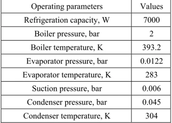
Table 1 Operating condition of the ejector
Operating parameters Values
Refrigeration capacity, W 7000
Boiler pressure, bar 2
Boiler temperature, K 393.2
Evaporator pressure, bar 0.0122
Evaporator temperature, K 283
Suction pressure, bar 0.006
Condenser pressure, bar 0.045
Condenser temperature, K 304
3.1
Analytical Simulation
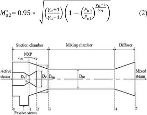
The schematic diagram given in Fig. 3 shows the various components and their arrangements in an ejector. Sections 0 to 5 are taken along the ejector for the convenient description of the flow.
of primary nozzle and negligible kinetic energy at the inlet of primary nozzle, suction port and exit of diffuser (Huang et al. 1999), both the primary and secondary fluids are chocked, secondary fluid is chocked at section 3 of the ejector, the primary fluid is dry saturated, complete mixing of the primary and secondary fluid within the mixing chamber and constant-pressure mixing of primary and secondary fluids are considered. A normal shock is usually developed in between the sections 3 and 4 (Bartosiewicz et al. 2005), therefore, in addition to the assumptions made, a normal shock at section 4 is assumed. The required thermo-physical properties of the fluid are taken from the property database REFPROP (NIST Standard Reference Database 23, 1980). All the equations are derived from the basic compressible fluid flow equations (Cengal and Cimbala, 2010). Based on the required refrigeration capacity mass flow rate of the passive steam is fixed. Any value less than one is initially assumed as entrainment ratio. From the adiabatic energy equation along the primary nozzle the Mach number at the exit of nozzle is obtained and it is as:
∗ = .95 ∗ − (2)
Fig. 3. Schematic diagram of an ejector.
The obtained Mach number shows that the active steam flow is supersonic and it possesses high momentum. The part of the momentum in the active steam is spent to entrain the passive steam from the evaporator. Therefore the impulse function after mixing will be equal to the difference between the impulse function of active and passive steam. Solving for impulse function, the Mach number at section 3 is derived and it is given as:
∗= ∗ ∗
∗ ∗
∗ ∗
∗ ∗
(3)
Where, ∗∗ is the local sound velocity ratio
between passive and active steam and it is given by:
∗ ∗ =
× × ×
× × × (4)
Due to the supersonic flow and the difference of pressure, a normal shock is formed and as mentioned before, it is assumed to be formed in section 4. Pressure ratio across the shock is the ratio between
the condenser pressure and pressure before shock. That is, the ratio between the pressure in section 5 to pressure just before section 4. By the basics of compressible fluid flow, the pressure ratio across the normal shock in section 4 is given by:
= ∗∗ +
∗
∗
(5)
Specific heat ratio at the mixing chamber γ3 is
calculated by weighted average and it is given as:
= + (6)
The pressure before the shock has to be equal to the required evaporator pressure. If the upcoming downstream pressure of the shock wave is not equal to the required evaporator pressure, the assumed entrainment ratio will be altered. When the downstream pressure is less than the required evaporator pressure, the entrainment ratio will be increased. If it is not the case, the entrainment ratio is decreased. By this procedure the actual entrainment ratio is calculated. Depending on this ratio, by applying momentum equation in sections 1, 2, and 3, various areas at the throat, exit of primary nozzle, annular entrainment for passive steam at section 2, and mixing chamber are calculated from equations 7, 8, 9 and 13.
The chocking mass flow rate in the primary nozzle ( ) is given by,
× ×
× =
(7)
From the above equation, area of nozzle throat can be calculated for the chocking condition.
Again by applying continuity equation in section 2, exit area of the primary nozzle can be found as given below,
= ∗ × + ×
∗ × (8)
The positioning of the ejector nozzle inside the suction chamber is decided based on the suction area or entrainment area, and it can be calculated as given below:
= × × × ×
∗
∗ × × (9)
The mixing chamber diameter is determined by considering the total mass flow rate of both the primary and secondary fluids, temperature, pressure and critical Mach number of the section.
The temperature (Tm), gas constant (Rm) and the ratio
of specific heat (m) of mixed stream are obtained
from the equations 10, 11 and 12.
= × × (11) = + × (12)
The continuity equation is solved for finding the constant area mixing chamber and it is given by:
= × × × × ∗
∗× × (13)
3.2
Numerical Simulation
The complex flow in ejector has led to increasing reliance on CFD as a design tool (Fan et al. 2011) and many researchers have agreed with CFD for predicting results closer to the experimental values (Rusly et al. 2005; Ruangtrakoon et al. 2013; Sriveerakul et al. 2007).
The entrainment diameter of 87.8 mm is analytically derived and few diameters above and below this value as given in Table 2 are taken for further numerical analysis. The convergent angles have been taken from 4 to 220. The other dimensions from the
analytical simulation are held constant and they are shown in Table 2.
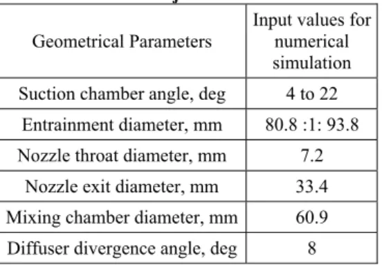
Table 2 Dimensions of numerically simulated ejector
Geometrical Parameters
Input values for numerical simulation
Suction chamber angle, deg 4 to 22
Entrainment diameter, mm 80.8 :1: 93.8
Nozzle throat diameter, mm 7.2
Nozzle exit diameter, mm 33.4
Mixing chamber diameter, mm 60.9
Diffuser divergence angle, deg 8
The CFD code selected for the simulation is the FLUENT module in ANSYS 13. The model is created in 2D domain and 3D effects have been modelled by using the axisymmetric solver. As the flow expected is supersonic, turbulence compressible flow has to be modelled. The governing equations for compressible fluid (ANSYS FLUENT User’s Guide, 2010) in the compact Cartesian form are:
+ = (14)
+ = − + (15)
+ + = ∇. +
∇. (16)
= + − (17)
Pressure-based solver has been selected to solve the governing equations. As the active steam flying out of the primary nozzle is modelled to have supersonic
velocity, the Reynolds number is around 7×10⁶ and
hence the flow is turbulent. But the secondary fluid flow from the evaporator has very low Reynolds number of around 2000. Therefore, it is necessary to select a turbulent model which can accurately predict both the high and lower Reynolds number flow. The turbulence model k--RNG is such a model which can accurately handle both the higher and lower Reynolds number (ANSYS FLUENT User’s Guide, 2010). Also, in the previous studies this model was chosen and were used effectively (Chen et al. 2011; Zhu et al. 2009; Bartosiewicz et al. 2005). This model relies on the Boussinesq hypothesis. According to this hypothesis, the momentum transfer caused by molecular motion in gases which can be described by a molecular viscosity Reynolds stress tensor is proportional to the traceless deformation rate tensor.
= + − +
(18)
The main advantage of this approach is the relatively low computational cost associated with the determination of the turbulent viscosity (Bartosiewicz, Aidoun, Desevaux, and Mercadier, 2005). The boundary conditions are selected as pressure inlet and pressure outlet. Steam is assumed as an ideal gas because, for the lower operating conditions, as used here, the variation of results between the real gas model and the ideal gas model is quite negligible (Sriveerakul et al. 2007).
3.3
Validation with the Available
Experimental data
The results from the analytical and numerical simulation were validated with the experimental data available in literature (Ruangtrakoon et al. 2011) for an ejector with the dimensions given in Table 3.
Table 3 Dimensions of the ejector used for validation
Geometrical parameters, mm
Dimensions of experimental
ejector
Nozzle inlet diameter 7.5
Nozzle throat diameter 2.6
Nozzle exit diameter 11.63
Nozzle exit position 23
Mixing chamber diameter 19
Mixing chamber length 114
Suction chamber length 130
Subsonic diffuser length 180
Ejector outlet diameter 40
Table 4 Experimental and simulated results
Ejector Tboiler (°C)
Tevap
(°C) ω
Error,
ω (%)
Experiment 111.2 7.5 0.262 -
Analytical
Simulation 111.2 7.5 0.342 30.65
Numerical
Simulation 111.2 7.5 0.31 18.32
Table 4 gives the comparison between theoretical results and the experimental values reported in the literature. The analytical values of entrainment ratio are higher than the values in literature. This deviation is mainly due to the assumptions made in analytical simulation. While comparing the numerical simulation results, the entrainment ratio is also higher than the experimental values. The possible reason for this deviation might be due to some assumptions like perfect gas, frictionless and adiabatic walls and so on. Therefore the deviation of this simulated result from the experimentation is tolerable. And, therefore, the same procedure is used for further numerical analysis with the dimensions derived.
4. RESULTS AND DISCUSSION
It is known that entrainment ratio is the factor which decides the performance of the ejector. Therefore, for various combinations of entrainment diameter and suction chamber angles the entrainment ratio is derived. The obtained results are investigated with the help of post-processing facility in CFD software. Contours of Mach are predominantly used to analyse the flow within the ejector.
4.1
Flow Within Ejector
The contour of Mach number along the ejector for the suction chamber angle of 18° and the entrainment diameter of 90.8 mm is shown in Fig. 4. At the exit of the convergent divergent nozzle there forms the first series of oblique shock. In case of over expanded wave these shock waves are not so strong wherein under expanded wave it gives a strong barrier to the flow. It is clear from the figure that for all the models, the expanding wave from the primary nozzle is over-expanded as the flying wave from the nozzle is having a convergence angle. This type of wave is more desirable for the ejector’s performance (Ruangtrakoon et al. 2011). The flying primary fluid from the nozzle exit and the suction chamber wall forms a convergent duct. This causes the secondary fluid from the evaporator to get accelerated and to choke at some position of that convergent duct. The annular area corresponding to this is known as effective area (Huang et al. 1999). Therefore, for the optimum performance, the ejector must be operated at double-choking mode. The gradual mixing of active and passive steam happens after passing through the effective area. During the mixing, the momentum of the primary fluid is gradually transferred to the secondary fluid. After mixing, due to high pressure in downstream, a series of secondary oblique shock waves are created. Due to these shock
waves and diffuser, the mixed fluid obtains its required condensing pressure.
Fig. 4. Mach contour for Ө1 = 18° and Den = 90.8
mm.
4.2
Effect of Suction Chamber Angle and
Entrainment Diameter
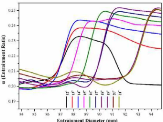
The influence of entrainment diameter on the entrainment ratio for various suction chamber angles is shown in Fig. 5. Each entrainment diameter has its own corresponding NXP depending on the suction chamber angle.
Fig. 5. Effect of various suction chamber angles over entrainment ratio for a range of
entrainment diameter.
Fig. 6. Variation of entrainment ratio of the suction chamber angles of 12° to 21°.
a) Den = 89.8 mm b) Den = 90.8 mm
Fig. 7. Variation of static pressure along the axial distance of ejector from nozzle inlet for the suction chamber angle of 18°.
suction chamber angles of 8°, 9°, 10°, 11° and 12°, the entrainment ratio increases with increase in entrainment diameter upto the entrainment diameters of 86.8 mm, 87.8 mm, 90.8 mm, 88.8 mm and 87.8 mm respectively and then started to decrease. This shows that, from 8° to 12° moving the primary nozzle away from the mixing chamber increases the entrainment ratio upto the entrainment diameters mentioned, after which it gets reduced. At the suction chamber angle of 120, a steep increment of
entrainment ratio at some entrainment diameter has been observed.
As shown in Fig. 6, after this particular entrainment diameter, entrainment ratio decreases gradually. This phenomenon existed up to 21º after which the increment and decrement of the entrainment ratio are found to be gradual and there is no significant increment.
The reason behind this flow phenomenon can be explained by Fig. 7. Fig. 7 (a) shows that the increase in static pressure at the exit of primary nozzle is higher when compared to the static pressure increase in the subsequent entrainment diameter as shown in Fig. 7 (b). The difference in pressure between each entrainment diameters is found to be 500 Pa. The entrainment diameter, which gives the maximum entrainment ratio and all the entrainment diameters above that have lower increase in static pressure at the exit of primary nozzle. This trend has been found to be similar for all the suction chamber angles from 12 to 21º.
The entrainment diameters having maximum entrainment ratio and their subsequent ones for the suction chamber angles of 12 to 21° are presented in Table 5. The corresponding entrainment ratio, nozzle exit position and the difference in static pressure are also presented. After 21º, for the entire entrainment diameters, there was no such steep increment in entrainment ratio. The reason for the increase in pressure at the exit of the nozzle is due to the formation of the first series of oblique shock waves. If these shock waves are strong, it will provide a strong barrier to the primary fluid flow from the nozzle. Therefore, the pressure increases and consequently, the momentum of the primary fluid
reduces and by which the flow cannot be smooth. This decrement in momentum will reduce the entrainment of secondary fluid; subsequently the entrainment ratio decreases. In all the cases, the second shock position is identical and it shows that the ejector can be operated at higher critical condenser pressure. Also, the maximum entrainment ratio is obtained while the nozzle is moved away from the mixing chamber, which in turn increases the annular area available for the passive steam to get accelerated.
Table 5 Difference in pressure increment at the nozzle exit zone for various suction chamber
Ө1, deg Den, mm NXP,
mm ω
P, Pa
12
86.8 45.52 0.2066 315 87.8 43.16 0.2333
13
86.8 41.91 0.2055 370 87.8 39.74 0.2392
14
86.8 38.80 0.2018 458 87.8 36.80 0.2457
15
87.8 34.24 0.2032 459 88.8 33.38 0.2461
16
88.8 30.25 0.2026 542 89.8 28.51 0.2520
17
89.8 26.74 0.2032 542 90.8 25.10 0.2506
18
89.8 25.16 0.2038 500 90.8 23.62 0.2535
19
92.8 19.39 0.2136 500 93.8 17.93 0.2525
20
92.8 18.34 0.2106 583 93.8 16.97 0.2520
21
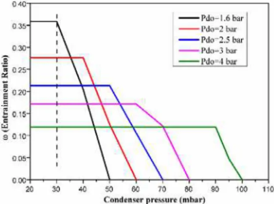
4.3 Effect of Condenser Pressure
The performance curve shown in Fig. 8 explains the effect of condenser pressure (back pressure for ejector) on the entrainment ratio. The performance curve is divided into three categories: choked flow (both active and passive streams were choked), unchocked flow (active steam is alone choked), and reversed flow (both fluids are not chocked and the active steam is forced into the evaporator). To get the maximum entrainment ratio the ejector must be operated at choked flow region and this region is separated from the unchocked flow region by critical pressure.
Fig. 8. Effect of back pressure (condenser pressure) over entrainment ratio for Ө1 = 18°
and Den = 90.8 mm.
The reason behind this can be explained with the help of Mach contours for various condenser pressure and it is shown in Fig. 9.
Fig. 9. Effect of back pressure (condenser pressure) on the contour of Mach number.
With the increase in condenser pressure the second series of oblique shock gets stronger. As the condenser pressure increases the shock wave moves
towards the mixing chamber. Due to this, the mixing phenomenon of passive steam with the primary steam gets disturbed, and with the further increase in condenser pressure the shock wave gets very strong and the entrainment of passive steam is prevented. For the operating condition defined in this study, the breakdown pressure is found to be 59 mbar. From 59 mbar to 40 mbar ejector can operate with the single choking condition, that is, active steam alone gets choked and the passive steam is not given with enough space to get choked in the mixing chamber. Below 40 mbar, ejector was able to operate with double-choking mode, which is more desirable for the higher performance of the ejector. This is due to the fact that in this mode, passive steam is allowed to get choked. As the mass flow rate of passive steam reaches its maximum limit, the entrainment ratio will be maximized. The pressure corresponding to this performance is known as critical pressure, which also varies with the change in other operating and geometrical conditions.
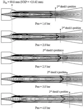
4.4 Effect of the Boiler Pressure
The effect of boiler pressure on entrainment ratio for various condenser pressure is given in Fig. 10. It can be clearly seen that, with the increase in boiler pressure, the critical back pressure is increased. This shows that ejector can be operated at higher condensing temperature with double chocking mode. But on the other hand, with the increase in boiler pressure, the entrainment ratio is decreased.
Fig. 10. Effect of boiler pressure on entrainment ratio for various condenser pressure.
Fig. 11. Effect of active steam pressure on the contour of Mach number.
5. CONCLUSION
In this study, an analytical simulation using MATLAB was carried out to derive the various important diameters of the ejector and then, a numerical simulation using ANSYS Fluent software was employed to investigate the effect of entrainment diameter for various suction chamber angles over the performance of the ejector. Based on the studies, the following conclusions are made:
The variation in results between numerical simulation and the literature experimental data available in the literature was found to be 18.32%. This proves that CFD is an effective tool for predicting the flow characteristics within the steam ejector.
Upto the suction chamber angle of 7°, entrainment ratio decreases with the increase in entrainment diameter. This also means that entrainment ratio decreases with the decrease in NXP. For suction chamber angle between 8 and 11°, entrainment ratio increases upto certain increment in entrainment diameter, and then starts to decrease.
From and above 12° suction chamber angle, at some entrainment diameters, there is a sudden increment in entrainment ratio, which has been found to be maximum, and above that particular entrainment diameter, the change in entrainment ratio is gradual. This phenomenon existed upto 21° and after which there is no such steep increment. Primary shock waves emerging at the primary nozzle exit zone are found to be responsible for the sudden increment in entrainment ratio.
The maximum entrainment ratio was obtained at the suction chamber angle of 18° with the
entrainment diameter 90.8 mm. The corresponding NXP is 23.62 mm. For this suction chamber angle, at the boiler pressure of 2 bar, the critical back pressure was inferred as 40 mbar and the breakdown pressure was 59 mbar.
With the increase in back pressure, the critical back pressure increases along with the decrease in entrainment ratio. The second series shock wave produced in the mixing chamber has a significant impact on entrainment ratio and the critical back pressure.
For all the suction chamber angle there is a specific NXP value which yields a maximum entrainment ratio and it will change with the variations in operating conditions only.
REFERENCES
Ameur, K., Z. Aidoun and M. Ouzzane (2015). Analysis of the critical conditions and the effect of slip in two-phase ejectors. Journal of Applied Fluid Mechanics 9, Special Issue 2, 213-222.
ANSYS FLUENT User’s Guide (2010). ANSYS, Inc. Southpointe, Canonsburg, PA.
Aphornratana, S. and I. W. Eames (1997). A small capacity steam-ejector refrigerator: experimental investigation of a system using ejector with movable primary nozzle. International Journal of Refrigeration 20, 352-355.
Ashrae. (1983). Steam Jet Refrigeration Equipment. In: Equipment Handbook, Atlanta, GA, USA: ASHRAE, Chapter 13.
Bartosiewicz, Y., Z. Aidoun, P. Desevaux and Y. Mercadier (2005). Numerical and experimental investigations on supersonic ejectors. International Journal of Heat and Fluid Flow 26, 56-70.
Cengal, Y. A. and J. M. Cimbala (2010). Fluid Mechanics Fundamentals and Applications, 3rd Ed., McGraw-Hill, New York.
Chen, S., G. C. Chen and L. Fang (2015). An experimental study and 1-D analysis of an ejector with a movable primary nozzle that operates with R236fa. International Journal of Refrigeration 60, 19-25.
Chen, W., D. Chong, J. Yan and J. Liu (2011). Numerical optimization on the geometrical factors of natural gas ejectors. International Journal of Thermal Sciences 50, 1554-1561.
Eames, I. W., A. E. Ablwaifa and V. Petrenko (2007). Results of an experimental study of an advanced jet-pump refrigerator operating with R245fa. Applied Thermal Engineering 27, 2833-2840.
ESDU (1985). Ejector and jet pump, data item 86030. ESDU International Ltd, London, UK.
Fan, J., J. Eves, H. M. Thompson, V. V. Toropov, N. Kapur, D. Copley and A. Mincher (2011). Computational fluid dynamic analysis and design optimization of jet pumps. Computers and Fluids 46, 212-217.
Garcia del Valle, J., J. Saiz Jabardo, F. C. Ruiz, J. San Jose Alonso (2011). A one dimensional model for the determination of an ejector entrainment ratio. International Journal of Refrigeration 35, 772-784.
Huang, B. J., J. M. Chang, C. P. Wang and V. A. Petrenko (1999). A 1-D analysis of ejector performance. International Journal of Refrigeration 22, 354-364.
Jia, Y. and C. Wenjian (2012). Area ratio effects to the performance of air-cooled ejector refrigeration cycle with R134a refrigerant. Energy Conversion and Management 53, 240-246.
NIST Standard Reference Database 23 (1980). NIST Thermodynamics and Transport Properties of Refrigerants and Refrigerant Mixtures. REFPROP, Version 9.1.
Pianthong, K., W. Seehanam, M. Behnia, T. Sriveerakul and S. Aphornratana (2007). Investigation and improvement of ejector refrigeration system using computational fluid dynamics technique. Energy Conversion and Management 48, 2556-2564.
Ruangtrakoon, N., S. Aphornratana and T. Sriveerakul (2011). Experimental studies of a steam jet refrigeration cycle: Effect of the primary nozzle geometries to system performance. Experimental Thermal and Fluid Science 35, 676-683.
Ruangtrakoon, N., T. Thongtip, S. Aphornratana and T. Sriveerakul (2013). CFD simulation on the effect of primary nozzle geometries for a steam ejector in refrigeration cycle. International Journal of Thermal Sciences 63, 133-145.
Rusly, E., L. Aye, W. W. S. Charters and A. Ooi (2005). CFD analysis of ejector in a combined ejector cooling system. International Journal of Refrigeration 28, 1092-1101.
Sankarlal, T. and A. Mani (2005). Experimental studies on an ammonia ejector refrigeration system. International Communications in Heat and Mass Transfer 33, 224-230.
Sriveerakul, T., S. Aphornratana and K. Chunnanond (2007). Performance prediction of steam ejector using computational fluid dynamics, Part 1. Validation of the CFD results. International Journal of Thermal Sciences 46, 812-822.
Varga, S., A. C. Oliveiraa and B. Diaconu (2009). Influence of geometrical factors on steam ejector performance a numerical assessment. International Journal of Refrigeration 32, 1694-1701.
Yan, J., W. Cai and Y. Li (2012). Geometry parameters effect for air-cooled ejector cooling systems with R134a refrigerant. Renewable Energy 46, 155-163.
Yan, J., C. Lin, W. Cai, H. Chen and H. Wang (2016). Experimental study on key geometric parameters of an R134A ejector cooling system. International Journal of Refrigeration.
Zhang, B., X. Song, J. Lv and J. Zuo (2012). Study on the key ejector structures of the waste heat-driven ejector air conditioning system with R236fa as working fluid. Energy and Buildings 49, 209-215.