RENEWABLE ENERGY OPTIONS AND AN ASSESSMENT OF WIND-BASED
PROPULSION SYSTEMS FOR SMALL CRAFTS
Abdi KUKNER1 Sertac BULUT2
Akile Nese HALILBESE3
1
PhD, Professor, Department of Shipbuilding and Ocean Engineering, Faculty of Naval Architecture and Ocean Engineering, Istanbul Technical University, Istanbul, Turkey, [email protected]
2
PhD Student, Assistant, Department of Naval Architecture and Marine Eng., Faculty of Naval Architecture and Ocean Eng., Istanbul Technical University, Istanbul, Turkey, [email protected]
3
PhD Student, Assistant, Department of Naval Architecture and Marine Eng., Faculty of Naval Architecture and Ocean Eng., Istanbul Technical University, Istanbul, Turkey, [email protected]
Abstract: Increasing fuel prices and strong environmental concerns have changed the competitive landscape of the shipping industry today. The conventional propellers are still commonly used for marine propulsion, but the alternative propulsion systems become more prevalent, their advantages do as well. Because the environmental regulations for shipping are getting stricter, the marine propulsion systems based on renewable energy have recently received a large amount of attention. General strategies for reducing the small crafts dependence on oil for transportation include reducing energy use on the propulsion systems. In this respect, wind-assisted propulsion systems offer considerable options for introducing renewable power into shipping. The wind assisted systems generate thrust from the wind and thereby reduce dependence on fossil fuel and main engine operation. In this paper, alternative propulsion systems such as kite-assisted propulsion, Flettner rotor, and wind turbine systems and their applications to the small crafts have been investigated. Moreover, the working principles of each system have been analyzed in detail and compared in terms of their advantages. A detailed description of the systems had been explained how to obtain the daily energy to be needed and usage in yacht by harnessing renewable energy from the wind.
Keywords: Renewable Energy Sources, Wind Energy, Wind-Assisted Propulsion, Kite-Assisted System, Small Craft
INTRODUCTION
A ship navigating itself in water and airrequires overcoming the resistance force resulting from both environments in order to move at a certain velocity. The ship provides this through the lift force obtained by its propulsion system.
Today, the most common propulsion system is still propeller, but alternative propulsion systems have become widespread. The most important factors of this areincreasing oil prices and environmental concerns. The development of superior propulsion systems in terms of the energy efficiency and lifespan has become unavoidable to meet changing market conditions and economic requirements. Competitive market conditions necessitate minimizing operating costs. For this reason, the alternative energy systems such as natural gas, fuel cell systems, nuclear power, and the wind-based propulsion systems have been taken into account by ship builders. Wind-based propulsion systems are seen as an alternative way to reduce fuel consumption and avoid negative effects of ships on environment. Earlier studies have shown that the wind-based propulsion systems can now achieve the annual fuel saving in the range of 10 percent
and 30 percent.
In this study, it is explained how to obtain daily energy to be needed for yachts utilizing the wind-based propulsion systems such as kite systems, Flettner rotor and wind turbines. [1]
WIND-ASSISTED PROPULSION SYSTEMS Kite Systems
Wind energy, cheaper than heavy oil;seems as the most economic energy source of high seas. The wind-assisted propulsion systems can be defined as the systems which catch the wind and convert it to the electricity. These systems whether obtainto make the main machine Works at the lower power or increase the velocity of the vessel by using the same power.
The cost saving of the ship can be reduced from %10 to %35 considering the wind conditions by the virtue of the kite systems. At the optimal conditions, the amount of the cost saving reaches instantaneously about %50. Actually, all cargo ships and newly built ships can be equipped by the kite systems. In this respect, using binary propulsion systems offer a solution to minimize the operation cost.
39 DOI: 10.21279/1454-864X-16-I2-006
Figure 1. Yacht with kite [2]
It can be seen at the Figure 1 that the kite systems consist of three main components. These are a towing kite, a control system for automatic operation and a launch and recovery system. [2]
A Towing Kite
Instead of a traditional sail equipped with a mast, kite propulsion systems use large towing kites for the propulsion of the ship. Asit is seen in Figure 2, the towing kite is made of high-strength and weatherproof textiles.
Figure 2. Towing Kite [2]
The profile of the towing kite is designed in such a way that optimal aerodynamic efficiency can be achieved. Their double-wall profile gives the towing kites aerodynamic properties similar to the wing of an aircraft. The Figure 3 shows the operating conditions of the kite system in accordance with various wind angles. Thus, these systems can be operated not just downwind, but at courses of up to 50° to the wind as well. The highest propulsion power can be obtained the angle higher than 70 degrees. The optimum operating angle of the kite systems are between 120 and 140 degrees.
Figure 3. Possible Courses [2]
The power of the kite system can be reduced by changing its position into the wind area without decreasing the kite area is case of blustering winds. Nowadays, the area of towing kites used for cargo ships is between 150 and 600 m2. [2] Force Transmission
The tractive force of the kite system is directed to the ship over the force transmission point assembled on the foredeck. The force transmission point, also called "tow point", is the point at which the towing rope of the kite is connected to the ship.
Figure 4. The tractive force of the kite system [2]
As it is understood from the Figure 4, the pulling force obtained and transmitted to the ship by the kite system is equal to the force applied by the tug supply vessel having the same power as the kite system.
The towing kite is recovered and launched using an operating winch, which also serves as rope storage. The tractive force measurement is carried out by means of the winch. The winch speed can be chosen so as to stabilize the towing kite at any time. [2]
40 DOI: 10.21279/1454-864X-16-I2-006
Launch and Recovery System
The launch and recovery system controls the deployment and lowering of the towing kite. The telescopic mast rises the towing kite from the kite stowage during the launch process. When the mast extends to its operating height, the towing kite unfolds to its full size and is launched. The recovery process is performed in the reverse order of the launch. An example of the launch and recovery systems can be seen inFigure 5. The entire launch and recovery procedure is performed automatically and takes approximately 15 mins each. [2]
Figure 5. The launch system [2]
Control System
The control system consists of the control pod and the control computer. The functionality of the control pod is comparable to the pilot of a paraglide. It pulls to the left and right of the control lines, thereby modifying the aerodynamic profile of the towing kite and controlling its flight path. The main purpose of the control computer is to manage the kite system automatically. It is similar to the autopilot of a plane in terms of collecting the data from the kite system and processing them. [2]
Cost
It is estimated that it can be possible to obtain 1kWh power at cost of 6 USDwhich is reasonable price compared to other systems. It is also equal to half of the cost of the power generation attained by the same powered marine engine. The fuel saving achievable due to these systems is around %10 to %15.[2]
Forces on Kite
A kite can be considered as a wing surface which enables the application of three principle forces acting on the kite. These forces are the weight, the aerodynamic force, and the pulling cable tension.
As it is shown in Figure 6, the weight always acts from the center of gravity toward the center of the earth. The aerodynamic force is usually consists of two main components: one of them is the lift force, which acts perpendicular to the wind and the other is the drag force acts in the direction of wind.[3]
Figure 6. Forces on a kite [3]
The aerodynamic force effects on the center of pressure. Because there is turbulence in the earth’s boundary layer, the wind moves gulfy near the ground. But the wind is rather stable and almost parallel to the surface of the earth. In this case the lift is directly opposed to the weight of the kite, as shown in the figure 6.
The tension on the pulling cable can be divided into two main components: the vertical pulling force Vp and the horizontal pulling force Hp. As Newton’s first law of motion, the forces on the kite remain constant in case of stable flight and there is no external force acting on the kite. Thereby, the sum of the forces is zero in the vertical direction. In the same way, it can be said that the sum of the horizontal pull and the resistance must also equal zero.
Vp + W - L = 0
(1)
Hp - D = 0 (2)
The relative magnitude of the components of the tension changes with the bridle angle. Near the bridle point, the line is inclined at the bridle angle.
Tanβ = Vp / Hp (3)
The height at which the kite flies can be predicted by knowing the bridle angle, the length of line, and the weight of line.
As described by Newton’s laws of motion, the relative strength of the forces determine the motion of kites. The lift and drag increase when a gust of wind effects on the kite. The kite moves vertically upsince the lift is higher than the weight, and the tension force increases because of rising drag.
Consequentially, the system now has a new balance point and the kite attains a different stable condition. The kite also moves around the bridle point to balance the torques because of the change in aerodynamic and weight forces.[3,4] Total Aerodynamic Force
The components of aerodynamic forces are 41
DOI: 10.21279/1454-864X-16-I2-006
shown in Figure 7. The general formulization of these components aregiven as follows:
Figure 7. Traction aerodynamic force and cable Tension [5]
Fw = Resistance Force L= Lift Force
Taf= Total aerodynamic force C= Chord
t= Towing cable tension (The value is equal to Taf)
α = Incidence angle of wind V = Wind velocity
Kc = Application center of forces CL = Lift coefficient
CD = Drag coefficient
AKT =The total area of the kite
(4)
(5)
(6)
The projection of aerodynamic force Taf on water plane WP is shown in the Figure 8. As the the ship weight is considered, the value of the lift force Fz can be negligible because it has a small value compared with the weight. The resistance force Fy causes the deviation from the route of the ship.. [3,4]
Figure 8. The projection of the forces on the
water plan [3]
Having the kite area as500 m2, the lift and dragcoefficients will be, CL=1.0 and CD=0.286,respectively,which is given in the literature. The equilibrium angle of attack for the kite is αkite=tan-1
(CD/CL) = 15.9. The wind acts on the kite with the velocity of 10 m/s and its direction is assumed to be constant. The air density is also assumed to be constant and its value is taken as 1.225 kg/m3. The values of lift, drag and total aerodynamic forces can be calculated by using the equation 4, 5, and 6. As a result of calculations, the kite’s profile is described above, the lift force is obtained as 30625 N, the value of the resistance force is 8758.75 N, and the total value of the aerodynamic force is 31852.886 N.
The Flettner rotor made its appearancein the 1920s as seen in Figure 3.12.The Flettner rotor utilizes the Magnuseffect of fluid mechanics, where if windpasses across a rotating cylinder a liftforce is produced. This force has a linearrelationship with wind speed and, unlikeconventional sails or airfoils, a truecross-wind relative to the ship will producea useful forward thrust at any ship speedeven when this is greater than the windspeed. For a large ship, Flettner rotors can provide a small but significant proportion ofthe total propulsive power. However, thevorticity produced by a rotor is complex anda full understanding of the mechanismsis still evolving, principally through themeans of computational fluid dynamics.The vorticity in the wake of a rotor raisesthe issue of vortex interaction if morethan one rotor is fitted to a ship. Thisrequires exploration for a particular design, particularly with respect to any interferencewith the ship’s superstructure or highfreeboard under certain wind conditions.
Flettner Rotor
Flettner Rotor system is another method for the utilization of the wind power.Itutilizes the Magnuseffect of fluid mechanics, where if wind passes across a rotating cylinder a lift force is produced. This force has a linear relationship with wind speed. It is a kind of conventional sails or airfoils. The rotating drum, also called Flettner-Thom rotor, is a large mechanical sailing. It is inspired from the idea of based on a delicate and rotatable tower which can take place 10 times the size of a sail area. Thom disc can be located outside of the cylinder or it can be used without Thom disc as well. This idea was put forward at the1920’sby Anton Flettner. An experimental ship with the rotor have been built by Abert Betz, Jacob Ackeret, Ludwig Prandtl and Albert Einstein, along with the Flettner. As shown in Figure 9, this prototype ship for Flettner Rotor
42 DOI: 10.21279/1454-864X-16-I2-006
was named ‘Buckau’.
Part of drag on the system is a result of the permanent tip vortex. It is generated by the positive pressure on the under surface to the negative pressure on the upper surface. Flettner added discs to the tops of the rotor to reduce the effect of vortex. Thom obtained very much lift coefficients by using multiple discs or fences with the rotor system. The Figure 9 shows a view of Cloudia Catamaran used Magnus Flettner rotor with Thom fences. [5,8]
Figure9. Cloudia Catamaran with Tom Rotor [5]
The length of Flettner rotor varies with the flow speed and vertical speed depends on the ratio of length to weight. Sailing ships have a large number of crew needed for the management of the sails. It is maintenance costs are also very high. In Flettner rotor systems, a truecross-wind relative to the ship will producea useful forward thrust at any ship speedeven when this is greater than the windspeed. It can be achieved in an equivalent effect with reducing the sail area. When the rotor speed is zero only their area is exposed to wind resistance and the sail area is only exposed to wind resistance. For a large ship, a small but significant proportion ofthe total propulsive power can be provided by the Flettner rotor. However, thevorticity produced by a rotor is complex anda full understanding of the mechanismsis still evolving, principally through themeans of computational fluid dynamics. The vorticity in the wake of a rotor raisesthe issue of vortex interaction if more than one rotor is fitted to a ship. Thisrequires exploration for a particular design, particularly with respect to any interferencewith the ship’s superstructure or highfreeboard under certain wind conditions [13].
The rotor effect was shown in 1982 by the experiments carried out by H. Gustav Magnus. Magnus. He examined the impact of a projectile under the effect of the wind and, as a ballistic expert, published the experiment’s results in the article of “The deflection of bullets”. German technician, Anton Flettner (1885-1961), continued to study on this subject by developing Flettner Rotor.
Flettner firstly wanted to use aerofoil instead of sail as he inspired by aircraft construction. But he couldn’t find a solution to reduce the profile area during the storm. He made investigation on the rotors at Göttingen in 1923. After the research, he began to conduct experiments with model ships in Wannsee, Berlin. In 1924, three-mastedsailer Buckau was converted to the rotor ship and started to cruise. He applied for patent related to the Flettner rotor in 23 August 1923, and his application was accepted in 4 November 1924. Buckau, was built in 1920 as a three-mastedsailer by Krupp Germany Shipyard in 1920.
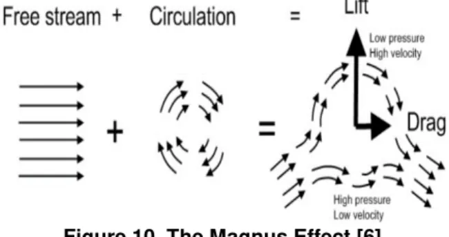
Figure 10. The Magnus Effect [6]
Considering the theories of a spinning cylinder hit by free stream, Magnus effect causes a lift and a drag as shown in Figure 10. The rotor size, angular velocity and free stream velocity are the most important factors on these forces. While the air mass at one side of the rotor is slowed down the air on the other side is accelerated. The lifting force is made up by the pressure difference between each side. The Kutta-Joukowski law describes the relationship between lift per length of rotor Lr, and circulation Cras follows:.
where
w is the angular velocity, and r is the radius of the rotor.
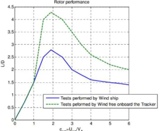
Whereas the Kutta-Joukowskilaw are usually used in theory, Some empirical data values are used to obtain more accurate results in analysis. Figure 11 presents the data related to the rotor performance for two different experimental measures conducted by Bergeson in 1985.
The coefficient Crot represents the relationship between the rotational speed of rotor Urot and the apparent wind speed VA. The rotation speed is limited to 1000 rpm based on the test resultswhich isgiven in thereference[6].
43 DOI: 10.21279/1454-864X-16-I2-006
Figure 11 The rotor performance for two different experimental measures [6] Urot= Crot.VA (9) The average lift coefficient of the rotor based on several independent empirical data by Bergeson is shown in Figure 12. No data is available beyond Crot=5, as seen in the figure.
Figure 12. The average lift coefficient of the rotor based on several independent empirical
data [6]
In 1983 the Spins’l project used a smaller vessel and declared a 50-66% fuel save at 6.5 knots, but it was observed that when the amount of fuel consumptionfor rotation of the rotor wassubtracted, 20% fuel were saved. This is the clear evidence that the rotor requires energy to rotate. The total required power for the rotation of the rotor is calculated by means of the plate friction theory. The Reynolds number Re, which is needed for calculation of frictional coefficient Cf, can be expressed as;
where
The frictional coefficient Cf is expressed as a function of Reynold number. The followingequation is valid at both laminar and turbulent boundary layer as well as high and lowReynold numbers.
The frictional force Ff
whereAr is the surface area of the rotor [6]
The power, Pr, which is needed to rotate the rotor, can becomputed from the following expression:
Figure 13. Lift Force [7]
The rotating cylinder acts as an airfoil (Figure 13) but airfoil produces a lift force by withstanding much less resistance without mechanical movement. For rotating cylinder, the lift force and drag force can be expressed as follows:
The coefficients of cq and cw was measured in Göttingen Aerodynamic Test Centre in 1924. These coefficients, as a function of the rotation speed u and the wind speed v, is given as follows;
u/v=2 cw=1.4 cq=4.7 u/v=3 cw=3.6 cq =8.2 It is assumed that the wind speed is 12 m/s., the surface area of rotor is 231 square meter, the height is 33 meter, the diameter is 7 meter, and the rotation speed is 36 m/s. The ratio of u/v is to be 3. Therefore, the lift force FL and the drag force FD are determined as 166 kN and 73.5 kN, respectively.[8]
Nowadays, “E-Ship 1”, which is used by Enercon Company for transporting of wind turbine components on the purpose of fuel saving, is one of the current example of the Flettner rotor application. As shown in the Figure 14, “E-Ship” 1 has four rotor, 25 meter in length. The ship is 130 meter in length, 22.5 meters in width, and it has 44
DOI: 10.21279/1454-864X-16-I2-006
23500 kW of engine power. It is estimated that using the Flettner rotor in the ship provide 30 percent of fuel saving.[8,9]
Figure 14. E-Ship1, Enercon [8]
Wind Turbine Propulsion on Ships
The applicability of wind turbines on yachts is much more complicated than those for photovoltaics, but the general criteria ismostly same. The usage of wind power is effective if you are away from the dock at least 6 months of the year and cruise in windy areas. It would be an unnecessary investment in the case of the usage of the boat during only one month of the year.
The most of marine wind turbines are with horizontal axis and most of them consist of yacht implementations. They are usually derived from the onshore featured designs and adapted for vessel mounting and marine environment. These wind turbines are in the power range of 400 W to 1kW, and partly used to meet the electricity needs of the boat. The implementations of such systems are generally used lighting systems in ports or when moored.
Therefore, one of the most important aspects in marine applications is the size of vessel and location of the wind turbines.Placing thewind turbineson the deck of a vessel, where they will not affect the functioning of vessel and the comfort of the crew memberwould be appropriate. On the other hand,integration of wind turbines on large vessels would need big size turbines and would require large mounting and energy storage areas. Unfortunately this part remains uncertainty but has to be taken into consideration.As seen in Figure 15, the best location for the turbine emplacement is considered on the mast without affecting the ship geometry negatively.[10]
Figure 15. Wind Turbine on a Catamaran [10]
Getting Power from the Wind
The electrical power obtained from the wind can be calculated as follows:
where P = power in watts K = 0.0653
E = mechanical efficiency in % dR= blade diameter in meters w = wind speed in knots
The power output of a wind turbine having the blade diameter of 1.52 meters and efficiency of 30% in a steady 15-knot wind;
The equation emphasize that efficiency, diameter and wind speed are the most important factors in selecting and sizing of a wind machine to obtain a boat’s electrical demand.
The efficiency of the wind machine, E, will never be 100%.Because the turbine blades cannot be able totransfer the %100 of the kinetic energy from the wind to the machine. As a result of the theoretical calculations, it is estimated that the aeronautical efficiency of a wind machine is 59.3 % but, the actual efficiencies are around 30% because of the losses in the generating coils, rotor bearings, and transmission gearing. Diameter, dR, enters the equation as a power of square. Doubling blade diameter quadruples power output. Most marine wind machines have blade diameters of either 1 m (39 inches) or 5 feet (1.52 m). Wind speed, w, is the most important factor of all because it enters the equation as a cubic power. [11,12]
Estimating Daily Output
Selecting right size wind machine is different from designing other systemsin many aspects such as solar system panels. While there are a variety of other systemsizes to select from, two sizes of wind machine are generally used such as 1.52 meter or 5 feet blade diameter.
Assuming that the area swept by wind blades is (π × D2/4), as shown in Figure 16. So,
45 DOI: 10.21279/1454-864X-16-I2-006
Watts = π×D2×E×P/4
where: π= 3.14 D = blade diameter in meters
E = wind machine efficiency, 0.00 to 1.00 P = annual wind power in W/m2
Assuming: E = 0.30 (30%): Watts = 0.24 D2×P
(19)
kWh/yr = 2.10 D2×P (20)
Ah/day = 0.44 D2×P (21)
Figure 16. Areas Swept by 5-Foot and 1 m Wind Generator Blades[12]
The power expecting from a wind machine of 5-foot (1.52 m) blade diameter, with 30% efficiency, and 12 foot height in protected harbors;
Assuming harbor locations, at 12 foot (3.66 m) height the available power is 60% of power at 33 feet (10 m). Both locations have average wind power of about 100 W/m2 at 33-foot height, according to the data related to average wind power in New England and the Florida Keys.[11,12]
Watts = 0.24 D2×P = 0.24 x 1.522× 0.6 x 100 = 33 watts
kWh/yr = 2.10 D2×P
= 2.1 x 1.522× 0.6 x 100 = 292 kilowatt-hours Ah/day = 0.44 D2×P
= 0.44 x 1.522× 0.6 x 100 = 61 Ah
Technical Specifications
Theoretically, the efficiency of the wind turbine is not directly related to the number of blades. A two-bladed wind turbine can have the same efficiency as the six-bladed machine. However, the noise level is reduced by increasing the blade diameter and the number of blade. All six-bladed turbines operates more silent comparing to two-bladed and three-bladed turbines. Output power varies depending on the diameter squared, thus generating the larger power is possible with the bigger blade diameters. But the increasing of the diameter causes the rising of noise, weight and potential danger. Light weight makes the machine easier to handle, but light weight may lead to the unstable construction and smaller continuous rated output. [11,12]
Mechanical Installations of Wind Turbines on Sails
Figure 17 shows a common large wind machine and all its possible configurations on a 35-foot ketch. Stern pole is the most common mounting option and the pole is generally 2-inch (5 cm) schedule-40 or 80 pipe. Pole mount also has some advantages, such as its accessibility from deck and being usable in case of under sail. Smaller output, relatively high noise level and potential danger for crew can be seen as its disadvantages. The other location for wind turbines is above mizzen mast. Especially for boats, with a second mast, mizzen mounts provide greater output by raising the wind turbine and decreases the potential danger. Raising a wind machine seems as an advantage as it increase the output power, but it can be more dangerous in case of shutdown or recovery of halyard mounting machine especially in a high wind.[12]
Figure 17. All possible Configurations of a Wind Turbine on a Ketch [12]
CONCLUSION
Nowadays, Ship building industry as well as other industries concerns about climate change require the reduction of greenhouse gas emissions from the shipping sector due to fossil fuels release of toxic gases into
46 DOI: 10.21279/1454-864X-16-I2-006
the air.Therefore the industry must prepare for the new future and investigate alternative, more economic ship propulsion systems. In the case of other propulsion options, the subject renewable energy is concerned. Renewable energy sources are free from exhaust pollutants. However, wind-based solutions tend to be limited to propulsion augmentation roles unless a full return to sail is contemplated in specific applications. For new ship buildings planned in the near feature, depending on ship size and intended use, combination systems are also used.
The importance of renewable energy sources has now become undeniable. In this study, it is aim to point out the positive impacts of the usage of green energy on environment in terms of energy efficiency and cost. The selected systems are wind turbines, Flettner rotors and kites.
Compared to other systems, kite systems are a new technology using for ship propulsion. The calculation of the forces on a specific kite under certain conditions is performed. It is clear that kite propulsion gives good results and the usage of these systems with main engine creates a new opportunity for ship propulsion.
One of the major advantages of the kite systems is that kite systems can work 150-200 meters above the water, so it works above the turbulent boundary layer of wind and it means 30-70 % more energy is available to the kite. The other advantage is that there is not any dangerousoverturning moments inherent in masts and sails when kites power the boats.
Flettner rotor system is another method for the utilization of the wind power. The rotor used in our example calculations has 231 square meter of surface area, and 33 meters of height. When the wind speed is 12 m/s and the rotation speed is 36 m/, the value of drag and lift are determined 73.5 kN and 166 kN, respectively. An advantage of the Flettner system is allowing a possibility to add several rotors in one boat which are increasing the propulsion power all the way up to 20 percent, but this is obviously very dependable to the ship characteristics.However, the high efficiency can be obtained. These systems are not preferable due to the aesthetic concerns.
The applicability of wind turbines on yachts are also examined in the last part of the study. The expected average electrical power from a wind machine and estimating daily output has been determined. The possible configurations of a wind turbine on a ketch type sailing yacht are investigated.
Wind power systems rely on the wind strength to be effective and the use of some systems is dependent on adequate control system technology being installed on board the ship.
It is evident that to optimize the potential benefits of a propulsion option, or combination of options, in terms of efficiency and minimizing the impact on the environment, an integrated ship design procedure based on a systems engineering approach must be employed.
To develop future renewable alternative energy system for ship propulsion; some research and funding are needed in a number of areas, such as kites, wind turbine, fuel cells, solar cells, Flettner rotors capable of sustainable powers for ship propulsion.
BIBLIOGRAPHY
[1] Celik, F., “GemiSevkineGiriş, SevkŞekilleri, PervaneGeometrisi, PervaneÇizimi”, Yildiz Technical University.
[2]SkySails GmbH & Co. KG Company, https://www.skysails.info/
[3] Grosan, N., Dinu, D., “Considerations Regarding Kite Towed Ship’s Manoeuvering”, Constanta Maritime University, Romania.
[4] Harun, H.B., “Wind Assisted Propulsion System For Fuel Saving”,University of Technology Malaysia, 2011. [5] http://www.sdtb.de/Flettner-Rotor.1623.0.html
[6] Silvanius, M., “Wind Assisted Propulsion For Pure Car and Truck Carriers”, KTH Centre for Naval Architecture, 2009.
[7] https://de.wikipedia.org/wiki/Flettner-Rotor
[8] Arikan, Y., Dogrul, A., Celik F., “GemiSevkleriTarihineGiris”, GemiDenizTeknolojisi, Istanbul, 2010 [9] Ragheb, M., “Wind Energy Converter Concepts”, 2014.
[10] Ionescu, R.D., Ioan, S., Vlase, S., Ivanoiu, M., Munteanu, R., “Innovative Solutions For Portable Wind Turbines, Used on Ships”, Romania, 2014.
[11] “How A Sail Boat Sails Into The Wind”, https://web.mit.edu/2.972/www/reports/sail_boat/sail_boat.html
[12] Wing, C., “Boat Owner’s Illustrated Electrical Handbook”,2006.
[13] “Future ShipPoweringOptionsExploring alternative methodsof ship propulsion”, Royal Academy of Engineering, July 2013.
[14] “Ship Propellers and Propulsion Systems (in Turkish)”, Güner, M., Kukner, A. and Baykal M. A., Book, published by ITU, Istanbul, Turkey, 1999.
[15] http://worldmaritimenews.com/archives/36748/germany-solarwaterworld-skysails-introduce-emission-free-solar-yacht/
47 DOI: 10.21279/1454-864X-16-I2-006
![Figure 2. Towing Kite [2]](https://thumb-eu.123doks.com/thumbv2/123dok_br/18143283.326707/2.893.112.395.131.348/figure-towing-kite.webp)
![Figure 6. Forces on a kite [3]](https://thumb-eu.123doks.com/thumbv2/123dok_br/18143283.326707/3.893.110.388.357.584/figure-forces-on-a-kite.webp)
![Figure 7. Traction aerodynamic force and cable Tension [5]](https://thumb-eu.123doks.com/thumbv2/123dok_br/18143283.326707/4.893.86.425.171.361/figure-traction-aerodynamic-force-and-cable-tension.webp)
![Figure 15. Wind Turbine on a Catamaran [10]](https://thumb-eu.123doks.com/thumbv2/123dok_br/18143283.326707/7.893.94.417.194.398/figure-wind-turbine-on-catamaran.webp)
![Figure 16. Areas Swept by 5-Foot and 1 m Wind Generator Blades[12]](https://thumb-eu.123doks.com/thumbv2/123dok_br/18143283.326707/8.893.86.379.133.599/figure-areas-swept-foot-m-wind-generator-blades.webp)
