The effect of transverse shear on the face
sheets failure modes of sandwich beams
loaded in three points bending
BOUROUIS FAIROUZ
University Mentouri Constantine, Mechanical Department, Algeria Email : [email protected]
MILI FAYCAL
University Mentouri Constantine Faculty of Engineering Science, Laboratory of Mechanics Chaab Ersas 25000 Constantine, Algeria
Abstract
Sandwich beams loaded in three points bending may fail in several ways including tension or compression failure of facings. In this paper , The effectof the transverse shear on the face yielding and face wrinkling failure modes of sandwich beams loaded in three points bending have been studied, the beams were made of various composites materials carbon/epoxy, kevlar/epoxy, glass/epoxy at sequence [+θ/-θ]3s, [0°/90°]3s. . The stresses in the face were calculated using maximum stress criterion and the simple beam theory. The obtained different results show that the sandwich beams with carbon/epoxy, and glass/epoxy face sheets are the best materials, in return the kevlar /epoxy facing characterised by low resistance of transverse shear in compression and tensile.
Keywords: Beam theory, Maximum stress criterion, Transverse shear, face wrinkling, face yielding.
1. Introduction
Sandwich composites consist of two thin face sheets with high stiffness and high strength and a core with low density and low stiffness.. Sandwich structures exhibit complex failure mechanisms including face sheet compressive, failure adhesive, bond failure , indentation failure , core failure and facing wrinkling. A large number of theoretical and experimental investigations on sandwich structures have been published in the literature, core failure by shear studied by Allen [1], Hall and Robson [2] and Zenkert [3].Triantafillou [4] studied failure modes of sandwich beams with aluminum face sheets and a rigid polyurethane foam core. Failure maps for various core densities and span to depth ratios were constructed for face yielding, face wrinkling ,core yield in shear , and core yield in tension and compression. Niu and Tareja [5] presented a model for the analysis of wrinkling behavior of sandwich panels in compression. They gave a single expression for the wrinkling stress for the single sided face wrinkling stress for the single sided face wrinkling , and the in phase and out phase wrinkling .They showed that the wrinkling stress in all three cases in almost the same for short wave length wrinkling. El sayed and Sridharan [6] used finite element analysis to examine the compressive behavior of sandwich columns with a variety of imperfections .Kim and Dharam [7] focused on buckling of the debonded face sheet and extended the delamination buckling model of Vizzini and Lagace [8] to debonded sandwich specimens.
2. Three points bending of sandwich beams
Table 1 : Mechanical characteristics measured on various unidirectional fiber epoxy composite
We consider the symmetric sandwich beams with two identical skins with orthotropy directions parallel to the direction x and y . The normal stresses are given by relation :
D
Q x b4
Ph k
11 * 11 k
xx
(1)
The stresses are maximum for x= l/2 and P is the total load applied at middle of beam The transverse stress xzk can then be deduced from equilibrium equation.
0 z x
k xz k
xx
(2)
k xx
normal stress of the kth layer given by :
kxz
11k 11*
z ck
b4 Ph D
Q
(3)
The constants ck are determined by setting k xz
to zero on the upper and lower faces, and by ensuring the continuity of xz from layer to layer.
And Dij The bending stiffness ,
66 26 16
26 22 12
16 12 11
ij
D D D
D D D
D D D
D (4)
The inverse matrix of
Dij given by
2 26 66 22 *11 D D D
1
D
(5)
is the determinant of the matrix
Dij , Dij hCij2 (6)2 ij
C the stiffness coefficients in the upper skins
k k n1
k k
ij 2
ij Q e z
C
2
(7) Mechanical characteristics
Glass E/epoxy
Carbon HR /epoxy
Kevlar 49/epoxy
Fiber volume fraction Vf 0.6 0.6 0.6
Longitudinal young’s modulus El(Gpa) 46 159 84
Transverse young’s modulus Et (Gpa) 10 14.3 5.6
Longitudinal shear modulus Glt(Gpa) 4.6 4.8 2.1
Poisson ratio lt 0.31 0.32 0.34
The tensile strength in longitudinal directionXt(Mpa) 1400 1380 1400
The compressive strength in longitudinal direction Xc(Mpa) 910 1430 280
The tensile strength in the transverse direction Yt (Mpa) 35 40 15
The compressive strength in the transverse direction Yc (Mpa) 110 240 50
The reduced stiffness constant of unidirectional or orthotropic composite, off its material directions:
2 2
66 12 4
22 4 11
11 Q Cos Q Sin 2Q 2Q Sin Cos
Q
4 4
12 2 2 66 22 11
12 Q Q 4Q Sin Cos Q Sin Cos
Q
Q Q 2Q
SinCos
Q Q 2Q
Sin CosQ 12 22 66 3
3 66
12 11
16
2 2
66 12 4
22 4 11
22 Q Sin Q Cos 2Q 2Q Sin Cos
Q
366 22 12 3
66 12 11
26 Q Q 2Q Sin Cos Q Q 2Q Sin Cos
Q
4 4
66 2 2 66 12 22 11
66 Q Q 2Q Q Sin Cos Q Sin Cos
Q (8)
The preceding relation allow us to express the reduced stiffness constants as functions of the engineering constants in the material directions we obtain:
tl lt l 11
1 E Q
, 11
l t
22 Q
E E
Q , Q12 ltQ22, Q66 Glt (9)
3. Failure modes of sandwich materials
A sandwich material must have the strength to carry the design loads without failing in one of the possible failure modes figure 1 [10].
Fig.1. Some failure modes a) Face yielding /fracture , b) Core shear failure , c) and d) face wrinkling , e) general buckling , f) face dimpling , g) local indentation.
If the beam fails by face yielding, the normal stress in the face at the critical section f equal the yield stress of
that faceyf.
k xx f f
y
(10)
The compression face of a sandwich beam subject to bending is likely to fail by a particular kind of local instability described as wrinkling. The local buckling of wrinkling or face wrinkling occurs when the normal stress in the face reaches the local instability stress.
4. Results and discussion
In order to study the effect of transverse shear stress in the face sheets failure modes of sandwich beams loaded in three points bending , we considered the faces made of various composite laminates ( glass/ epoxy, carbon/epoxy or kevlar /epoxy) of stacking sequence [+θ/-θ]3s and [0°/90°]3s with unidirectional fiber reinforced
at 60 %.
4..1.The effect of transverse shear on face yielding and face wrinkling failure modes in sandwich beams with various face sheets materials oriented at [0° /90°]3s
Fig.2. Variation of transverse shear stress through the Fig .3. Variation of transverse shear stress through thickness in sandwich beams with carbon/epoxy face the thickness in sandwich beams with glass/epoxy sheets oriented at [0°/90°]3s face sheets oriented at [0°/90°]3s
Fig.4.Variation of transverse shear stress through the thickness in sandwich beams with kevlar/epoxy face sheets oriented at [0°/90°]3s
Figure 2 shows the variation of the transverse shear stress through the thickness of the higher skin of a sandwich beam with carbon/epoxy face sheets oriented at [ 0°/90°]3s. We notices that the curves represent the
six layers have a linear form and that the value of shear stresses is higher in the face wrinkling failure mode than
-28 -26 -24 -22 -20 -18 -16 -14 -12 -10 -8 -6 -4 -2 0 5,0
5,2 5,4 5,6 5,8 6,0 6,2 6,4 6,6 6,8 7,0 7,2 7,4 7,6 7,8 8,0
z (m
m
)
Transverse shear stress N/mm2
face wrinkling
face yielding
-25,0 -22,5 -20,0 -17,5 -15,0 -12,5 -10,0 -7,5 -5,0 -2,5 0,0 5,0
5,2 5,4 5,6 5,8 6,0 6,2 6,4 6,6 6,8 7,0 7,2 7,4 7,6 7,8 8,0
z (m
m
)
Transverse shear stress N/mm2
(face wrinkling)
(face yielding)
-22,5 -20,0 -17,5 -15,0 -12,5 -10,0 -7,5 -5,0 -2,5 0,0 5,0
5,2 5,4 5,6 5,8 6,0 6,2 6,4 6,6 6,8 7,0 7,2 7,4 7,6 7,8 8,0
Transverse shear stress N/mm2
z (
mm)
the face yielding, we can say that the sandwich beams with carbon/epoxy face sheets resist better the transverse shear stress in compression than in tensile.
Figures 3 and 4 show that the value of transverse shear stress is more significant in face yielding failure mode than the face wrinkling failure mode for the sandwich beams with glass/epoxy and kevlar/epoxy coatings when we approaches to the core, the value of the transverse shear stress become similar for the two failure modes .
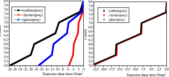
Fig. 5. Variation of transverse shear stress through Fig. 6. Variation of transverse shear stress through the thickness with various face sheets materials the thickness with various face sheets materials oriented at [0°/90°]3s in face wrinkling failure mode oriented at [0°/90°]3s in face yielding failure
mode
Figures 5 and 6 show the variation of the transverse shear stress through the thickness of sandwich beams with various face sheets materials. In the case of the face wrinkling failure mode ;figure 5 shows that the sandwich
beams with coatings carbon/epoxy resist better the effect of transverse shear stress than glass / epoxy and the kevlar/epoxy is the least resistant material. Figure 6 shows that the value of transverse shear stress is almost similar for the three materials in face yielding failure mode.
4.2. The effect of transverse shear on failure modes in sandwich beams with various face sheets materials oriented at [+θ° /-θ°]3s
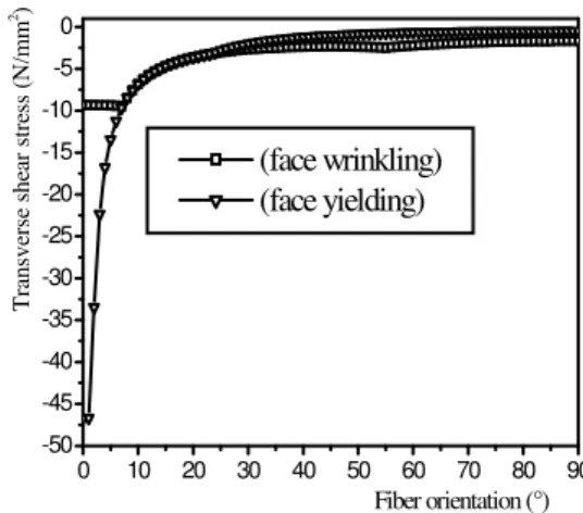
The figure 7 shows that for small values of fiber orientation from 0° to 3° the transverse shear stress of sandwich beams with carbon/epoxy face sheet is very important in face wrinkling failure mode than in face yielding failure mode ,and when the fiber orientation are between 4° to 33° the transverse shear stress is similar for the two failure modes and from 34° to 90°, the carbon/epoxy is the best material in face wrinkling than in face yielding failure mode .
Figure 8 shows that for small values of the fiber orientation from 0° to 7° the value of transverse shear stress is very significant in face yielding than in face wrinkling failure mode , we notice that the sandwich beams resists the effect transverse shear in tensile than in compression. from 8° to 90° the transverse shear stress value is almost similar for the two failure modes.
-28 -26 -24 -22 -20 -18 -16 -14 -12 -10 -8 -6 -4 -2 0 5,0
5,2 5,4 5,6 5,8 6,0 6,2 6,4 6,6 6,8 7,0 7,2 7,4 7,6 7,8 8,0
z (m
m
)
Transverse shear stress N/mm2 (carbon/epoxy)
(kevlar/epoxy) (glass/epoxy)
-22,5 -20,0 -17,5 -15,0 -12,5 -10,0 -7,5 -5,0 -2,5 0,0
5,0 5,2 5,4 5,6 5,8 6,0 6,2 6,4 6,6 6,8 7,0 7,2 7,4 7,6 7,8 8,0
Transverse shear stress N/mm2
z (
m
m
)
Fig .7. Transverse shear stress in sandwich Fig .8. Transverse shear stress in sandwich beams at z=h/2 with carbon /epoxy face sheets in beams at z=h/2 with kevlar /epoxy face sheets in face wrinkling and face yielding failure modes face wrinkling and face yielding failure modes
Fig .9. Transverse shear stress in sandwich beams at z=h/2 with glass /epoxy face sheets in face wrinkling and face yielding failure modes
Figure 9 shows that for small values of the fiber orientation sandwich beams with glass/epoxy face sheets resist better the effect of transverse shear in face yielding than in face wrinkling failure mode ,from 5° to 26 ° the value of the transverse shear stress is similar for the two failure modes . from 27° to 90° the sandwich beams resist better the effect of transverse shear in compression than in tensile.
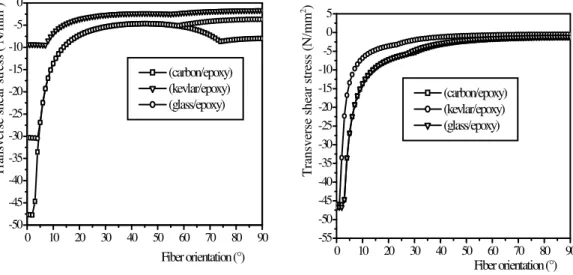
From figure 10 we distinguishes three zones, the first relates to the angles between 0° and 4° the value of transverse shear stress is higher for the sandwich beam with carbon/epoxy than with glass/epoxy and the kevlar/epoxy coatings. From 5° to 58° the transverse shear stresses value is similar for the sandwich beams with carbon/epoxy and glass/epoxy face sheets . From 59 ° to 90° it is always the carbon/epoxy the best material and kevlar/epoxy the least resistant material in face wrinkling failure mode taking the effect the transverse shear.
From 0° to 57° figure 11 shows that the value of transverse shear stress is similar for the sandwich beams with glass/epoxy and carbon/epoxy face sheets , when the fiber orientation is between 58° and 90° the three materials have a similar resistance in face yielding failure mode taking the effect of transverse shear.
0 10 20 30 40 50 60 70 80 90
-50 -45 -40 -35 -30 -25 -20 -15 -10 -5 0
T
ra
n
sv
erse
she
ar
str
ess
N/m
m
2
Fiber orientation (°)
(face wrinkling) (face yielding)
0 10 20 30 40 50 60 70 80 90
-50 -45 -40 -35 -30 -25 -20 -15 -10 -5 0
Tra
n
sve
rse
she
ar
stre
ss
(N/m
m
2)
Fiber orientation (°) (face wrinkling) (face yielding)
0 10 20 30 40 50 60 70 80 90
-50 -45 -40 -35 -30 -25 -20 -15 -10 -5 0
T
ran
sv
erse she
ar
st
ress (N
/m
m
2 )
Fig. 10.Transverse shear stress in sandwich beams Fig. 11.Transverse shear stress in sandwich beams at z= h/2 with various face sheets materials in face at z= h/2 with various face sheets materials in face wrinkling failure mode yielding failure mode
5. Conclusion
Sandwich structures, constructed by bonding two stiff, thin-walled face sheets to a light weight , relatively flexible thick core, are widely used in various industrial applications demanding a high bending stiffness per unit weight. Sandwich beams are know to exhibit a number of possible failure modes, including failure of the core in shear, in compression and failure of faces. In this study , the face yielding and face wrinkling failure modes of sandwich beams loaded in three points bending have been studied. The beams were made of various composite materials carbon/epoxy , kevlar /epoxy, glass/epoxy at sequence [+θ/ -θ]3s, [0°/90°]3s.The effect of
transverse shear on the facings failure modes has also been studied in this paper. Results shows that the face yielding and face wrinkling failure modes depend on the transverse shear, on the type of loading, constituent materials properties, and the fiber orientation of face sheet materials.
Reference
[1] Allen, H.G. (1969). Analysis and design of structural sandwich panels. Pergamon, London .
[2] Hall ,D.J. ; Robbon ,B.L . (1984): A review of the design and materials evaluation programme for the GRP/foam sandwich composite hull of the RAN mine hunter. composites , 15, pp.266-276.
[3] Zenkert .D. (1995). An introduction to sandwich construction, Chameleon, London.
[4] Triantafillon T.C.; Gibson L.J. (1987): Failure mode maps for foam core sandwich beams. Materials Science and Engineering, 95 , pp.37-53.
[5] Niu. K.;Talreja.R. (1999): Modeling of wrinkling in sandwich panels under compression .J.Eng.Mech.125, pp.875-883.
[6] El-Sayed, S. ;Sridharam, S. (2002): Imperfection-sensitivity of integral and debonded sandwich beam under compression . J Sandwich Stru Mater , 4, pp.49-69 .
[7] Kim, WC.; Dharam ,CKH. (1992): Face sheet debonding criteria for sandwich panels under in-plane compression.Eng Fract Mech,4,pp. 643-652.
[8] Vizzini ,AJ.;Lagace, PA. (1987): The buckling of a delaminated sublaminate on an elastic foundation .J.Compos.Mater,21 ,pp.1106-1117.
[9] Berthelot, J.Marie.(1996). Mechanical behaviour of composite materials and structures. Masson ,Paris.
[10] Lukkassen ,D.; Meidell ,A. (2007) .Advanced Materials and structures and their fabrication. Processes, Book manuscript. Navic University college, Hin.
0 10 20 30 40 50 60 70 80 90
-50 -45 -40 -35 -30 -25 -20 -15 -10 -5 0
T
ransverse she
ar stress ( N
/m
m
2 )
Fiber orientation (°) (carbon/epoxy) (kevlar/epoxy) (glass/epoxy)
0 10 20 30 40 50 60 70 80 90
-55 -50 -45 -40 -35 -30 -25 -20 -15 -10 -5 0 5
Tran
svers
e
sh
ear st
ress
(N/m
m
2 )
![Figure 2 shows the variation of the transverse shear stress through the thickness of the higher skin of a sandwich beam with carbon/epoxy face sheets oriented at [ 0°/90°] 3s](https://thumb-eu.123doks.com/thumbv2/123dok_br/18201083.333493/4.892.452.756.360.607/figure-variation-transverse-stress-thickness-higher-sandwich-oriented.webp)