Journal of Engineering Science and Technology Review 8 (3) (2015) 136-142
Research Article
The Creep Properties of Fine Sandstone under Uniaxial Tensile Stress
Jiang Haifei1*, Xie Yuanguang1, Zhao Baoyun2 and Xue Kaixi 3
1International College, Chongqing Jiaotong University, Chongqing 400074, China
2School of Civil Engineering and Architecture, Chongqing Universityof Science and Technology, Chongqing 401331, China
3 Civil and Environmental Engineering Department, College of Engineering and Computer Science, California State University, Fullerton,
800 N. State College Blvd, CA92834, United States
Received 2 March 2015; Accepted 14 September 2015
___________________________________________________________________________________________
Abstract
A graduated uniaxial direct tensile creep test for fine sandstone is conducted by adopting a custom-designed direct tensile test device for rock. The experiment shows that the tensile creep of fine sandstone has similar creep curve patterns to those of compression creep, while the ratios of the creep strain to the total strain obtained in the tensile tests are substantially higher than those obtained for similar compression tests, which indicates that the creep ability of rock in the tensile process is higher than that in the uniaxial compression process. Based on the elastic modulus in the approximately linear portion of the obtained isochronous stress-strain curves of the tensile creep, the time dependence of the elasticity modulus for the Kelvin model is evaluated, and a revised generalized Kelvin model is obtained by substitution into the generalized Kelvin model. A new viscousplastic model is proposed to describe the accelerated creep properties, and this model is combined in series with the revised generalized Kelvin model to form a new nonlinear viscoelastic-plastic creep model that can describe the properties of attenuation creep, steady creep, and accelerated creep. Comparison of the test and theoretical curves demonstrates that they are nearly identical, which verifies the performance of the model.
Keywords: Fine sandstone, Direct tensile test, Creep, Nonlinear creep model, Model identification
__________________________________________________________________________________________
1. Introduction
In the traditional view, if it is assumed that rock can sustain tensile stress at all, the deformations of rock under both compression and tension loads are generally identified as equivalent. However, in actuality, the uniaxial compressive strength of rock is much higher than its tensile strength, with the ratio of the two strengths ranging from 6 to 80 [1]. The difference between the compressive and tensile strengths of rock is so great, in fact, that actual rock engineering requirements obviously cannot be met under the assumption that deformations owing to the two stresses are identical. In the construction excavation process of slope engineering, mining engineering, and underground engineering, tensile stress will always be produced [2]. Moreover, tensile stresses may by no means lead to instability immediately after rock excavation and exploitation, but, rather, may require a considerable period of time. Because rock has little tensile strength, the presence of tensile stresses in rock engineering projects can be a decisive factor for the engineering stability. Therefore, the study of the creep properties of rock under conditions of tensile stress is of theoretical and practical significance.
Currently, thorough studies of the creep properties of rock under conditions of compressive stress are abundant and have achieved a great deal. Mishra et al. investigated the
time-dependent behavior of laminated shale based on the triaxial creep tests [3]. Gabriel et al. proposed a new empirical model that comprehends the three creep stages [4]. Wassmann et al. investigated the rheology of the plate interface dissolution precipitation creep in high pressure metamorphic rocks [5]. Julie et al. studied how interactions between brittle and viscous mechanisms lead to widespread transformation of the rocks and how a shear zone may evolve from a zone prone to earthquakes and postseismic creep to a zone of steady state creep [6]. Wei et al. developed a grain-based heterogeneous numerical model originated from the discrete element method, and the procedure is successfully applied to simulate uniaxial compression tests, Brazilian tests and uniaxial creep tests [7]. Gu et al. investigated the creep properties of sandstone under uniaxial compression [8]. M Schoenball et al. proposed to explain observations of delayed wellbore failure by time-dependent brittle creep, which has been observed for many types of rocks [9]. Siavash et al. investigate the time-independent behavior of grouting material and the creep tests of grouting material was conducted in triaxial compression apparatus at room temperature [10]. Hakan et al. proposed a mathematical modeling of the creep behavior of Tuzkoy rock salt based on the creep tests [11]. Karimpour et al. conducted triaxial compression tests on dense specimens of Virginia Beach sand at low and high
J
estr
Engineering Scienceand Technology Review
The main reason for the rareness in direct tensile creep properties are two-fold. Firstly, the restrictions of test conditions inhibit study in a laboratory setting, and, secondly, actual rock engineering projects predominantly consider conditions of compressive stress. However, with increasing investment in infrastructure, numerous large-scale and structurally complex rock engineering projects are presently under construction, which involve an increasing number of issues concerning rock deformation and instability under conditions of tensile stress. Therefore, the author has designed a direct tensile device for rock that can better avoid eccentric tension. Fine sandstone from a foundation pit in Chongqing was selected as the study object, and graduated uniaxial direct tensile creep testing was conducted. By considering the time dependence of the elastic modulus in the approximately linear portion of the obtained isochronous stress-strain curves, the equation for the viscoelastic modulus of a Kelvin model with respect to time is formulated, and a revised generalized Kelvin model is obtained by substitution into the generalized Kelvin model. The model obtained is combined with a newly proposed viscoplastic model in series to form a new viscoelastic-plastic creep model. The model parameters are identified utilizing the 1stOpt mathematics optimization software. The results presented in the present study may be of significant value to the stability issues of rock engineering.
2. Creep test
2.1 Test equipment
The test adopts a custom-designed direct tensile device for rock, which is mainly composed of a longitudinally-symmetric force support element (namely, a pull rod) and a pull head as well as high-strength nut, as shown in Figure 1. The test incorporates the simple loading device shown in Figure 2. The working principle is described in detail elsewhere [2].
(a) (b)
Fig. 1. Rock uniaxial direct tensile device. (a) schematic diagram. (b) image of actual device
(a) (b)
Fig. 2. Loading device for uniaxial direct tensile creep test. (a) schematic diagram . (b) image of actual device
2.2 Sample preparation and testing program
The rock sample used for testing is a fine sandstone obtained from a foundation pit in Chongqing, which is mainly comprised of quartz, feldspar, flint, and muscovite. The dry density is 2.33–2.74 g/cm3, porosity 0.63–0.71%, grain diameter 0.01–0.5 mm, uniaxial compressive strength 63.40 MPa, elasticity modulus 25.03 GPa, and Poisson ratio 0.13. Cylindrical samples of 50 mm diameter and 100 mm height were processed in accordance with ISRM testing regulations.
As shown in Figure 1, an axial and a lateral strain gages were pasted symmetrically in the middle region of each sample, which are used to measure the axial and radial strain of the sample. A DH3818 static strain test system comprised of a data collection box, microcomputer, and supporting software was adopted to collect the strain and stress of the specimen during the loading process, and is able to quickly measure the static strain and stress values of several points in large structures, models, and materials stress tests automatically, accurately, and reliably. Prior to conducting the tensile creep tests, tensile strength tests were first conducted on three fine sandstone samples, and the average tensile strength and tensile yield stress values were determined to be 1.78 MPa and 1.25 MPa, respectively. The reason for that is to determine the stress level in tensile creep test.
The creep tests were divided into two groups, and Table 1 lists the graduated test loading programs employed for each.
Table 1. Creep test programs for graduated loading of uniaxial tension. Specimen
No.
Stress level (MPa) /stress-strength ratios Level I Level II Level III Level IV
I 0.44/0.25 0.74 /0.40 1.04 /0.58 1.34 /0.75 II 0.53 /0.30 0.84 /0.47 1.14 /0.64 1.45 /0.81
2.3 Creep deformation analysis
0 50 100 150 200 250 300 1
2 3 4 5 6
7 1.34MPa
1.04MPa
0.74MPa
0.44MPa
Time/h
Axi
al creep
strai
n
/
10
-4
(a)
0 100 200 300 400 500
0 1 2 3 4 5 6 7 8 9 10
Axial creep strain
/
10
-4
Time/h
0.53MPa
0.84MPa
1.14MPa 1.45MPa
(b)
Fig. 3. Uniaxial tensile creep curves for fine sandstone. (a) specimen I. (b) specimen II
Based on the test results, the axial creep strain and total strain of the rock under the various levels of stress are listed in Table 2.
Table 2. Axial tensile creep strain and total strain of fine sandstone under the graduated loading listed in table 1.
Specimen
No. Stress (MPa)/ stress-strength
ratios
Axial strain
Creep strain
Total strain
Ratio of creep strain to total
strain (%)
I
0.44 /0.25 0.3442 1.5327 22.45 0.74 /0.40 0.6475 1.3115 49.37 1.04 /0.58 0.9385 1.7008 55.18 1.34 /0.75 1.0451 1.8648 56.04
II
0.53 /0.30 0.7861 2.2042 35.66 0.84 /0.47 1.2909 2.0655 62.49 1.14 /0.64 1.3294 1.8689 71.13 1.45 /0.81 0.6898 1.2794 53.91
It can be seen from Figure 3 that, for stress levels less than the yield stress, the creep curve can be divided into two stages: an attenuation creep stage and a steady creep stage. Under the highest stress level, a comparatively complete creep curve with three stages appear, that is, an attenuation creep stage, steady creep stage, and accelerated creep stage. The creep strain value increases with increasing stress, and the ratio of the creep value to the total strain also increases, which indicates that the creep strain of the rock accounts for an increasing percentage of the total deformation with increasing stress.
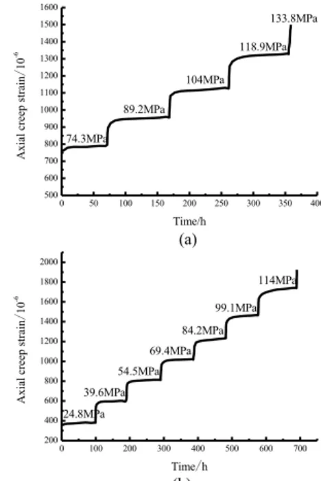
The processes of uniaxial compression creep shown in Figure 4, present a similar behavior to those processes shown in Figure 3. However, by comparing the test results of uniaxial tension and compression, we can find that the creep processes of the two differ greatly. In the tensile creep
However, in the literature [8], for the uniaxial compressive creep test of No. 4 fine sandstone, when the stress-strength ratio is 0.25, the ratio of the creep strain to the total strain is only 7.21%. In addition, when the stress-strength ratio of NO.3 fine sandstone is 0.30, the corresponding ratio of the creep strain to the total strain is 4.35% [8]. It can be observed that, under the same or similar stress-strength ratios, the ratio of the creep strain to total strain in the uniaxial tensile creep process is considerably higher than the corresponding value in the uniaxial compressive creep process.
0 50 100 150 200 250 300 350 400
500 600 700 800 900 1000 1100 1200 1300 1400 1500 1600
133.8MPa
118.9MPa
104MPa
89.2MPa
Axial creep strain
/
10
-6
Time/h 74.3MPa
(a)
0 100 200 300 400 500 600 700
200 400 600 800 1000 1200 1400 1600 1800 2000
114MPa
99.1MPa
84.2MPa
69.4MPa
54.5MPa
39.6MPa
Axial creep strain
/
10
-6
Time/h
24.8MPa
(b)
Fig. 4. Uniaxial compression creep curve for fine sandstone [8] (which belong to the same grade of sandtone with the specimen in main text). (a)uniaxial compression creep curve for a No. 3 specimen. (b) uniaxial compression creep curve for a No. 4 Specimen
2.4Isochronous stress-strain curve properties
Presently, studies of the isochronous stress-strain curves for rock under compressive stress are abundant, whereas those studies for rock under tensile stress are rare. Here, further studies are conducted of the isochronous stress-strain curves for rock under tensile stress. To this end, we select the strain values of the creep curves of specimens I and II at regular points of time under the various stress levels and obtain the stress-strain isochronous curves shown in Figure 5 for the fine sandstone samples during the tensile creep process.
0.6 0.8 1.0 1.2 1.4
St
ress
/
MP
a t=5h
t=10h
t=15h
t=20h
t=25h
t=30h
(a)
1 2 3 4 5 6 7 8 9
0.5 0.6 0.7 0.8 0.9 1.0 1.1 1.2 1.3 1.4 1.5
St
ress/M
Pa
Strain/10-4
t=5h t=10h t=15h t=20h t=25h t=30h t=40h t=50h t=60h t=70h t=80h t=90h t=100h
(b)
Fig. 5. Isochronous stress-strain curves. (a) specimen I. (b) specimen II
As observed in Figure 5, at lower stress levels, the creep deformation of the rock and the stress are essentially in a linear relationship. However, with increasing stress level, the isochronous stress-strain curve appears to be of an obvious nonlinear relationship. In addition, with increasing time, the isochronous stress-strain curves gradually deviate toward the strain axis, which indicates that the viscous deformation properties of the rock sample tend to develop with increasing strain.
3. Methodology
3.1 Revised generalized Kelvin model and its creep equation
From the results of uniaxial tensile test studies in recent years [13], [14], [15], [16], we find that the general shape of the stress-strain curves for both uniaxial tension and uniaxial compression are similar. Therefore, in reference to a creep model under compressive stress, a constitutive model to describe rock creep under tensile stress can be developed.
Figure 6 illustrates the Kelvin model in which the stress and strain of the spring body have a linear relationship, which means that the elasticity modulus is a constant. The stress-strain curves for most rock materials demonstrate such a relationship, while, in such a model, because the spring body and the viscous device are in parallel, the stress and strain of the spring body are no longer in a simple linear relationship. In the creep process, spring body deformation develops gradually with the passage of time, and ends instantly. Therefore, in the creep process, the elasticity modulus E of the spring body is no longer a constant, and changes continuously with the passage of time, such that E is given as E(t). The nature of the time dependence of E(t) can be obtained from the isochronous stress-strain curves of the creep process.
σ
η
E
σ
Fig. 6. Kelvin model [1]
In Figure 6, when the stress level is less than the yield stress, the rock is mainly a viscoelastic material, corresponding to the approximately linear portions of the
isochronous stress-strain curves. Therefore, a curve of the elasticity modulus with respect to time can be obtained through determining the elasticity modulus of the approximately linear portion at different points on the isochronous stress-strain curve, as shown in Figure 7.
0 10 20 30 40 50
2.0 2.1 2.2 2.3 2.4 2.5
Test Date Fitting Curve
Elasti
c Mod
ulu
s
/
GP
a
Time/h
(a)
0 20 40 60 80 100
1.36 1.38 1.40 1.42 1.44 1.46 1.48 1.50 1.52
El
ast
ri
c M
o
d
u
lu
s
/
GP
a
Time/h
Test Date Fitting Curve
(b)
Fig. 7. Elasticity modulus as a function of time.(a)specimen I. (b) specimen II
The test data of the elasticity moduli with respect to time
shown in Figure 7 were fit using the form E(t) =αexp(−βt)
whereαis a fitting parameter and βis a positive constant
representing the material nonlinearity, and the results listed in Table 3. From the R2 values given in Table 3, we can observe that the description of the creep viscoelastic modulus with respect to time using an exponential function is suitable.
Table 3. Creep test programs for graduated loading of uniaxial tension fitting results of E(t) =αexp(−βt).
Specimen No.
Fitting parameters
α β 2
R
I 2.5015 0.0052 0.9891
II 1.5018 0.0010 0.9377
If it is assumed that the elasticity modulus is E0 at t = 0,
then the boundary condition E(t)= E0 is established, and the
following form of E(t) can be obtained.
E t( )=E0exp(−βt) (1)
A revised generalized Kelvin model is thus obtained by
assuming that the elasticity modulus E2 of the spring body
in Figure 8, and assuming the elasticity modulus of the other spring is E1
.
σ
σ
η
1E
2(β,t)E
1Fig. 8. Revised generalized Kelvin model.
The corresponding state equation of the revised generalized Kelvin model is as follows:
1 1 2 2 2
2 0
t
E E
E E eβ
σ ε ε η ε•
−
⎫⎪
= = + ⎬
⎪
= ⎭
(2)
Here, σis the stress, ε is the strain, andηthe viscosity
associated with the viscous device η1 in Figure 8. The
corresponding constitutive equation from Eq.2 above is obtained as follows:
0
0
1 1
1
t
t E e
E e
E E
β
β
η σ• ⎛ − ⎞σ ηε• − ε
+⎜ + ⎟ = +
⎝ ⎠
(3)
Assuming that, at t=0, an instantaneous stress
σ
=
σ
0isapplied, and, with substituting the boundary
condition
ε
(0)=0 and solving the above differentialequation, we obtain the creep equation of the revised generalized Kelvin model as follows:
0 0 0
( )
1 0
1 exp
t
t t
E e t E E e
β
β
σ σ
ε
η
−
−
⎡ ⎛ ⎞⎤
= + ⎢ − ⎜− ⎟⎥
⎝ ⎠
⎣ ⎦
(4)
3.2 Nonlinear tensile viscoelastic-plastic creep model identification
3.2.1 Nonlinear viscoplastic body
From Figure 3, we can observe that, under the highest stress level, the strain of the rock is not limited to a particular value, but appears to be an accelerated flowing deformation; thus, when the tensile stress level exceeds the yield stress, the rock appears to be a viscoplastic material. Because the properties of a viscoplastic material are nonlinear, this material cannot be described by a traditional model like that given in Figure 6. Based on this, a nonlinear viscous model could be achieved through fitting and analog method, then combine it with a plastic device in parallel and to form a new nonlinear viscoplastic model by adopting the stress trigger method.
The accelerated creep portions of the curves in Figure 3 are fit by adopting the mixed power-exponent function given as follows:
0
nt Ate
ε=ε +
(5)
Table 4. Fitting results of the accelerated creep portion for specimens I and II based on Eq.5.
Specimen No. ε0 A n R2
I 6.6507E-4 9.2384E-30 0.2366 0.977 II 8.6849E-4 3.3742E-18 0.0697 0.985
From the values of R2 listed in Table 4, we can observe
that the fitting results to the direct tensile accelerated creep portion of the curves in Figure 3 using Eq.5 are relatively good. For the two-component viscoplastic model, when
S
σ >σ , where σS is the yield strength which is the stress
required to cause the local macroscopic plastic deformation, the creep equation is as follows.
0 s
t
σ σ
ε ε
η −
= +
(6)
Setting Eq.5 and 6 equal to one another and taking
0
s A
σ σ
η −
= the nonlinear equation of η for the viscous
device can be obtained as follows.
0
0 0
( , )n t nt t nt
e e
η η
η = =
(7)
Here, t0 is the reference time to be set as 1 and η0 is the
initial viscosity coefficient of accelerated creep.
σ
sη
2(n,t)σ
σ
Fig. 9. Nonlinear viscoplastic model.
The obtained nonlinear viscoplastic model is as shown in Figure 9, the creep equation of which is given as follows.
0 0
( )
0
( ) ( )
exp( ) ( , )
S S
t
H H
t nt n t
σ σ σ σ
ε
η η
− −
= =
(8)
Here, His given by the following.
(
)
(
)
0 0
0 0
0
( ) S
S
S S
H σ σ σ σ
σ σ σ σ
⎧ ≤
⎪ − =⎨
− ≤
⎪⎩
3.2.2 Nonlinear viscoelastic-plastic creep model
A series combination of the revised generalized Kelvin model and the newly proposed nonlinear viscoplastic model is presented to obtain a new nonlinear viscoelastic-plastic creep model appropriate for rock, as shown in Figure 10.
σ
η2,ε2 E2(β,t),ε2
E1,ε1
η(n,t),ε3 σ
When σ0≤σS, the model is transformed into the revised
generalized Kelvin model. Whenσ0>σS, the model is a
five-component nonlinear viscoelastic-plastic model. The corresponding state equation is as follows.
1 2 3 1 1 1 2 2 2 2 2
3 0 3 1 2 3 2 0
, ,
/ nt, , t
S
E E
te E E eβ
σ σ σ σ σ ε σ ε η ε
σ σ η ε ε ε ε ε
•
−
⎫⎪
= = = = = + ⎬
⎪
= + = = = = ⎭
(9)
The above formula is arranged to obtain the corresponding constitutive equation as follows.
0 1 2
1 0 1 2 1 0
0
1 0 2
0
( )
( )
( )( )
nt
t t
t nt
s
E te E E e E E E e
E E e n te
β β
β
η η σ
ε η ε σ
η
η σ σ
η
• •
− −
−
+
+ = + + +
+ −
(10)
In the above equation, σ and ε are the total stress and
total strain of the model, respectively; σ1,σ2and σ3 are
respectively the stresses corresponding to sections 1, 2, and 3 in Figure 10;ε1 ,ε2, and ε3 are respectively the strains
corresponding to sections 1, 2, and 3 in Figure 10;
0
E ,E1and E2 are the elasticity parameters of the rock
materials; and η2 and η0 are the viscosity parameters of the
rock, wherein η0 is the initial value of η( , )n t shown in
Figure 10.
Under the effect of constant stress, we assume σ=σ0
,
which is substituted into Eq.10, and the differential equation is solved to obtain the following creep equation of the
five-device nonlinear viscoelastic-plastic model given in Figure 10.
( )
0 0 0 0
( )
1 0 1 0
1 exp exp
t
S
t t
E e
t t nt
E E e
β
β
σ σ σ σ
ε
η η
−
−
⎡ ⎛ ⎞⎤ −
= + ⎢ − ⎜− ⎟⎥+
⎢ ⎝ ⎠⎥
⎣ ⎦ (11)
3.2.3 Determination of the model parameters
Before determining the model parameters, the Boltzmann superposition principle is first utilized to transform the creep curves under graduated loading conditions given in Figure3 into those under the respective loading conditions shown in Figure 11.
Based on the test results, the present study utilizes the 1stOpt optimization software to identify the model parameters. The core of the software is the Universal Global Optimization, the greatest feature of which that it alleviates the problems associated with establishing suitable initial values when using an iteration method in the optimization. As such, the user need not determine initial parameter values, which are determined randomly by the software, and the optimal solution is obtained through its unique global optimizing calculation.
When σ0≤σS , Eq.4 of the revised generalized Kelvin
model is adopted to conduct fitting to the test curve,whereas,
for σ0>σS , Eq.10 of the nonlinear viscoelastic-plastic
model is adopted to conduct fitting to the test curve. The
related parameters obtained are listed in Table 5. From the
R2 values of the fitting results, which are all greater than 0.98, we observe that the model fits the data quite well.
Table 5. Fitted parameters of the nonlinear viscoelastic-plastic creep model. Specimen
No.
Stress (MPa)/ stress-strength
ratios
0 E
(GPa)
1
E
(GPa)
β
(1) 1
η
(GPa•h)
η
(GPa•h)
n
(1) R2
I
0.44 /0.25 31.9525 3.7221 0.0102 155.9995 - - 0.9986 0.74 /0.40 24.7676 3.4996 0.0157 121.1304 - - 0.9961 1.04 /0.58 19.5424 2.9551 0.0147 201.4115 - - 0.9971 1.34 /0.75 11.5821 2.6397 0.0126 119.5005 9.4728E11 0.5838 0.9989
II
0.53 /0.30 22.7819 3.1443 0.0054 147.3809 - - 0.9870 0.84 /0.47 25.7224 2.3914 0.0062 336.9538 - - 0.9979 1.14 /0.64 20.7722 2.1809 0.0044 450.3242 - - 0.9988 1.45 /0.81 7.5487 1.2150 0.0996 52.4185 3.8838 E10 0.0283 0.9999
Figure 11 presents comparisons between the creep test curves and the curves derived from the theoretical model for fine sandstone under conditions of tensile stress. From the results, we observe that the two curves are rather identical, which not only demonstrates the optimization capability of the 1stOpt software, but also shows that the revised generalized Kelvin model and the nonlinear viscoelastic-plastic model proposed in the present study can accurately reflect the properties of attenuation creep, steady creep, and accelerated creep for fine sandstone under the effect of tensile stress, verifying the correctness of the proposed
model. 0 20 40 60 80 100
1 2 3 4 5 6 7
Axi
al creep
strai
n
/
10
-4
Time/h
Test Curves Theoretical Curves
0.44MPa 0.74MPa
1.04MPa 1.34MPa
0 10 20 30 40 50 60 70 80 90100 110 120 130 140 150 0
1 2 3 4 5 6 7 8 9 10
Axial creep strain
/
10
-4
Time/h Test Curves Theoretical Curves
(b)
Fig. 11. Comparison between the theoretical curves and test curves. (a) specimen I. (b) specimen II
4. Conclusions
The tensile creep and compression creep for fine sandstone exhibit similar curve shapes; however, the ratios of the creep strain to the total strain in the uniaxial tensile test are obviously higher than those in the compression test, indicating that the creep ability of rock in the uniaxial tensile process is higher than that in the uniaxial compression process.
A new revised generalized Kelvin model was proposed in the present study based on the elasticity modulus in the approximately linear portions of the isochronous stress-strain curves of the tensile creep, and the corresponding creep equation for this model was derived. By adjusting the
value of the nonlinear constant β in the model, it is possible
to describe the properties of attenuation creep and steady creep for different rock materials under stress conditions lower than the yield stress.
The revised generalized Kelvin model was combined in series with the proposed nonlinear viscoplastic model to form a new nonlinear viscoelastic-plastic creep model to describe the attenuation creep, steady creep, and the accelerated creep properties of rock materials.
Based on the creep test results, the 1stOpt optimization software was used to identify the model parameters, and the squared correlation coefficients obtained in the fitting process were all greater than 0.98. Comparison of the test curves with the model curves indicated that they were nearly identical, verifying that the proposed creep model can accurately describe the creep properties of fine sandstone under tensile stress.
Acknowledgements
This paper was financially supported by the Chongqing city Fundamental and Advanced Research Projects of China (cstc2015jcyjA90012), National Natural Science Foundation of China (No. 41302223), the Chongqing city Fundamental
and Advanced Research Projects of China
(cstc2013jcyjA90004) and the Doctoral Scientific Research
Foundation of Chongqing Jiaotong University (2014kjcⅡ
024).
______________________________
References
1. Zhao, B. Y., Liu, D. Y., and Zhu, K. S., “Experimental research on creep characteristics of Chongqing red sandstone under direct tension”, Chinese Journal of Rock Mechanics and Engineering, 30(S2), 2011, pp. 3960-3965.
2. Zhao, B. Y., Liu, D. Y., and Xue, K. X., “Experimental study on direct tension properties of red sa- ndstone in Chongqing”,
Geotechnical Investigation & Surveying, 39(4), 2011, pp. 9-12. 3. Mishra, B., and Verrna P., “Uniaxial and triaxial single and
multistage creep tests on coal-measure shale rocks”, International Journal of Coal Geology, 137, 2015, pp. 55-65.
4. Gabriel, E. M., and Cláudio, L. L. P., “New constitutive equation for salt rock creep”, Rem: Revista Escola de Minas, 67(4), 2014, pp. 397-403.
5. Wassmann, S., and Stöckhert, B., “Rheology of the plate interface Dissolution precipitation creep in high pressure metamorphic rocks”, Tectonophysics, 608, 2013, pp. 1-29.
6. Julie, R., Jean, P. G., and Mai, L. D., “Rock and mineral transformations in a fault zone leading to permanent creep: Interactions between brittle and viscous mechanisms in the San Andreas Fault”, Journal of Geophysical Research-Solid Earth, 119(11), 2014, pp. 8132-8153.
7. Wei, C., and Heinz, K., “Simulation of heterogeneity , creep, damage and lifetime for loaded brittle rocks”, Tectonophysics, 633, 2014, pp. 164-175.
8. Gu, Yn., “A study on creep properties of Xiaolongdi fine sandstone under uniaxial compression”, Chinese Journal of Rock Mechanics and Engineering, 5(4),1986, pp. 343-358.
9. Schoenball, M., Sahara, D. P., and Kohl, T., “Time-dependent brittle creep as a mechanism for time-delayed wellbore failure”,
International Journal of Rock Mechanics and Mining Sciences , 70, 2014, pp. 400-406.
10. Siavash, N., and Koroush, S., “Experiment creep tests and prediction of long-term creep behavior of grouting material”,
Arabian Journal of Geosciences, 7(8), 2014, pp. 3251-3257. 11. Hakan, Ö., Lhsan, Ö., and Sensogut, C., “Measurement and
mathematical modeling of the creep behavior of Tuzkoy rock salt”,
International Journal of Rock Mechanics and Mining Sciences, 66, 2014, pp. 128-135.
12. Karimpour, H., and Lade, P. V., “Creep behavior Virginia Beach sand”, Canadian Geotechnical Journal, 50(11), 2013, pp. 1159-1178.
13. Reinhardt, H. W., and Rinder, T., “Tensile creep of high-strength concrete”, Journal of Advanced Concrete Technology, 4(2), 2006, pp. 277-283.
14. Bao, C. Y., Tang, C. A., and Tang, S., “Research on formation mode and mechanism of layered rock surface fractures under uniaxial tension load”, Chinese Journal of Rock Mechanics and Engineering, 32 (3), 2013, pp. 474-482.
15. Nowak, and Krzysztof., “Time to failure size effect for tensile creep specimens”, Key Engineering Materials, 627, 2005, pp.185-188. 16. Ando, S., Yamada, H., and Nakano, K., “Evaluation on tensile