Stability Analysis and Control of Nonlinear
Phenomena in Buck Converters Using
Variable Structure Control Approach
M. SUBASHINI
Dept. of EEE, Rajalakshmi Engineering College, Rajalakshmi Nagar, Thandalam, Chennai-602105, India
C. KAMALAKANNAN
Sr. Lecturer, Dept. of EEE, Rajalakshmi Engineering College, Rajalakshmi Nagar, Thandalam, Chennai-602105, India
Dr. S. R. PARANJOTHI
Dean and Head, Dept. of EEE, Rajalakshmi Engineering College, Rajalakshmi Nagar, Thandalam, Chennai-602105, India
M. RAMASWAMY
Dept. of EEE, Annamalai University, Annamalai Nagar, Chidambaram- 608002, India
Abstract:
The time varying, nonlinear nature of the power switches and several other sources of nonlinearities in DC-DC Converters deviates its performance from the theoretical prediction of stability. The switching nature necessitates a study of the stability and their periodic orbit rather than the equilibrium point. The closed loop operation exhibits several types of nonlinear phenomena including bifurcation, chaos and quasi-periodicity. This paper is oriented with the analysis of such nonlinear phenomena in buck converter and attempts to coin a new strategy that can control chaos and significantly extend the parameter range for nominal period-I operation, in its mission to enhance the operating range of the converter.
KEYWORDS: Chaos, Bifurcation, Buck Converter, Variable Structure Control (VSC).
1. Introduction
The power electronic design engineers frequently observe some strange phenomena such as noise like oscillation. However the basic reason and the cause for its occurrence are not fully identified. The curious behaviour is termed under a special discipline called chaosis, which widely occur in nonlinear dynamical system. Chaos emanated as an undesirable phenomena due to its intrinsic instability and unpredictability. The existence of unstable periodic orbits, and sensitive dependence on initial conditions or non- periodicity of trajectories on the attractor are undesirable, since it results in increased losses, together with undesirable acoustic noise and may cause catastrophic failure of the unit. A chaotic system can reach an unlimited number of stages, all of them unstable and succeeding in a totally unpredictable manner. Since in certain situations chaos leads to serious problems or even catastrophic complications, the interest in discovering methods to control chaotic systems inherit a very solid practical purpose
The development of nonlinear dynamics in power electronic circuits has been reviewed. The numerical problems caused by the discontinuities in the state equations of power electronics has been discussed [Hamil (1995)]. A great variety of nonlinear behaviour has been observed to lead the dynamics of the voltage mode buck converter into chaotic region, when the input voltage is varied [Fossas (1996)]. A voltage mode PWM DC-DC converter has been modelled using a new discrete time map for the analysis of nonlinear phenomena [Bernado (1998)]. The change of behaviour of a current mode buck-boost converter has been clearly portrayed using bifurcation diagram. Prediction of the bifurcation points has been accomplished with the aid of Jacobian matrix [Cheung (2001)]. The stability of nominal period-1 orbit of a converter that can perform both buck and boost operation has been examined. To ensure stability in the periodic region, peak current control has been suggested for buck-like operation and for boost like operation; valley current control has been proved better for a wide range of stable region [Abdelali (2002)]. The bifurcations and chaos in the forward converter has been examined. The stability of the orbits has been studied by computing characteristic multipliers [Chuang (2007)]. The chaotic behaviour of the positive output Luo converter has been analyzed in the hysteric current mode control [Uma (2008)]. The bifurcations and chaos has been experimentally verified for a buck converter supplied from a rectifier [Biswarup (2010)]. A discerte-time map has been developed for duty cycle which is the control signal in the converters [Femat (2009)]. The potential application of chaos synchronization and dynamics of coupled system in field of communication has been indicated [Iu and Tse (2000)]. The strength of EMI in chaotic signal has been measured by prony method to improve the frequency resolution [Bozhang (2007)]. A novel design has been proposed to reduce EMI and to suppress ripples of output of converters [Halang (2008)].
The analysis of previous efforts proves the inability of the traditional average models of DC-DC converters to predict the nonlinear behaviour and suggest a nonlinear discrete model which maps the bifurcations and chaotic regions of the converter operations. A hallmark of chaos is its fundamental property of extreme sensitivity to initial conditions. The elimination of the chaos is equally significant and helps in determining the loadability of the converter. However, control of chaos targets at better managing the dynamics of a nonlinear system on a wider scale, with a hope that more benefits may thus be derived from the special features of chaos.It is aimed to choose the current tolerance of inductor of the converters as the bifurcation parameter to explore chaos. The time domain waveforms and phase portraits are expected to illustrate the creation and elimination of this non linear property. All previous works put forward that the chaotic behaviour of converters are undesirable in stability point of view. The real time problem encountered due to chaos is not revealed in a proper manner. Accordingly this mission is arrived to predict the adverse effect of chaotic behaviour on the performance of the DC-DC converters and it is proposed to develop a strategy in order to minimise such adverse effects and to ensure a stable operation over a wide range through VSC algorithm.
2. Design Methodology
2.1 Modeling of buck converter
Many chaos control methods are available for various applications. Their objectives fall into two general categories. In the first category, one of the infinitely many unstable periodic orbits within a chaotic attractor is first identified as the control target, and the control action is directed to stabilize the system so that it settles on the target periodic orbit. In the second category, a desired operating state is the control target, which is not necessarily one of those unstable orbits embedded in the chaotic attractor.
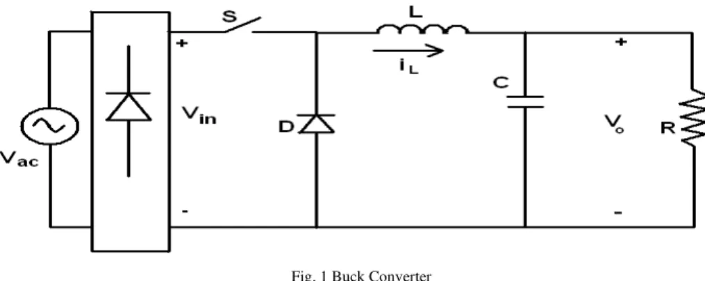
Fig. 1 Buck Converter
The switch is ON for time duration of DT and OFF for time duration of (1-D) T. The output voltage is therefore a fraction of the input voltage. The inductor current and capacitor voltage are chosen as the state variables. The matrix representation of the state space equations are in the form
When S is ON:
in o L o L
V
L
v
i
RC
C
L
v
i
dt
d
0
1
1
1
1
0
(1)When S is OFF:
in o L o L
V
v
i
RC
C
L
v
i
dt
d
0
0
1
1
1
0
(2)2.2 Design of control methodology
The DC-DC converter when operated under the open loop current limit control senses the inductor current to provide the duty cycle to the switch in the converter. The algorithm is designed in such a way that when the inductor current rises and reaches the upper limit, it forces the switch into the off state. When the reference current limits, in other words the tolerance of inductor current is varied to allow the system to deviate from the desired periodic trajectory and generate multiple periodic orbits and eventually reach the chaotic state. The approach seeks the use of Variable Structure Control (VSC) to accomplish stability even for large supply and load variations and facilitate good dynamic response. The desired philosophy is imbibed in the controller through a switching surface through switching function. The converter is forced to switch across this sliding surface by the construction of a switching control law, which requires the converter to satisfy a set of necessary conditions for the continuous existence of stability over the operating range.
The switching function proposed for this control scheme is given by:
K
X
G
X
)
(
(3)Where σ is switching function, G is gain vector, X is state vector and K is constant.
The sliding manner exists if all the state trajectories are directed towards the surface. The mathematical form for such a condition is given by:
0
(4)In order to obtain a continuous system, the above discontinuity may be replaced by a smooth continuous control law, which is given by:
0 ) ( )
( X X
The condition for the existence of the sliding line should be such that whatever the initial conditions, the system trajectories must reach the sliding line, and is given as:
(
)
0
0
)
(
X
X
X
X
(6)Where [X+] and [X-] are the steady state responses corresponding to the inputs m+ and m- respectively. Using the function given in equation (3), the switching function for buck converter is chosen to be:
C
1.
e
1 (7)Where C1 is constant gain, e1 is error in the output voltage and e1= Vref - Vo. A variable (u) is defined that
depends on the state of the switch(s), such that:
OFF
is
S
when
ON
is
S
when
u
0
1
(8)Thus the overall state space model is given by:
in o L o L
V
L
u
v
i
RC
C
L
v
i
dt
d
0
1
1
1
0
(9)and the control law is given by
0
;
0
0
;
1
u
(10)The condition for the existence of the control law to occur is given by:
RC
C 1
1
(11)
The sliding condition exists and the system moves along the designed trajectory as long as the above condition is satisfied.
3. Results and discussion
The performance of the proposed schematic is evaluated through Matlab based simulation. The buck converter parameters are chosen as L = 250H, C = 60F, R = 30, Fs = 20 KHz. A rectified DC of 350V is applied to the buck converter.
The duty cycle is calculated with a view to obtain 230V in the output and the corresponding steady state load current in this case is obtained as 7.67A. The buck converter is characterised such that the average inductor current determines the steady state load current. The consequent equal charging and discharging of the inductor with a constant average value serves to regulate the load current which in turn supports voltage regulation. The current limit control is enforced by varying the upper limit and lower limit of inductor current and ensuring its average value constant (Iref).
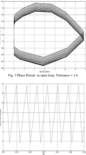
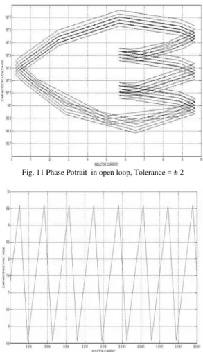
In the open loop current limit control, the time variation of the inductor current is shown in Fig 2. A periodic operation is exhibited as seen from the phase portrait in Fig. 3, when the tolerance is fixed at ± 6. However a collection of more orderly behaviour is noticed both in the inductor current waveform shown in Fig. 6 and the phase portrait depicts the region of operation corresponding to various sub-harmonic oscillations if the tolerance is reduced to ± 4 as seen in Fig. 7. The multiple periodic orbits seen in the inductor current waveform and phase portrait in Figs10 and 11 corresponds to a tolerance of ± 2.
trajectory that spirals into a fixed one period orbit as seen from Figs. 5, 9 and 13 and there by extracts the stable equilibrium point.
Fig. 2 Inductor Current Waveform in open loop, Tolerance = ± 6
Fig. 3 Phase Potrait in open loop, Tolerance = ± 6
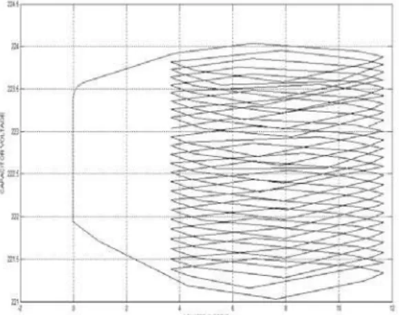
Fig. 5 Phase Potrait with VSC control, Tolerance = ± 6
Fig. 6 Inductor Current Waveform in open loop, Tolerance = ± 4
Fig. 8 Inductor Current Waveform with VSC control, Tolerance = ± 4
Fig. 9 Phase Potrait with VSC control, Tolerance = ± 4
Fig. 11 Phase Potrait in open loop, Tolerance = ± 2
Fig. 12 Inductor Current Waveform with VSC control, Tolerance = ± 2
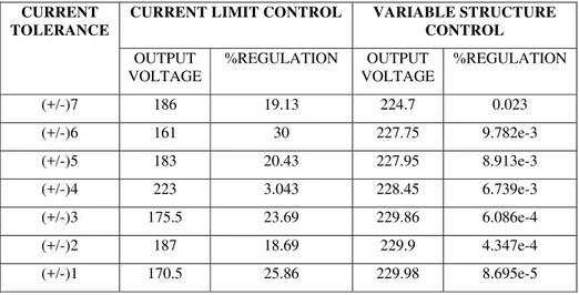
Table 1. Measurement of Voltage Regulation in Buck Converter
CURRENT TOLERANCE
CURRENT LIMIT CONTROL VARIABLE STRUCTURE CONTROL OUTPUT
VOLTAGE
%REGULATION OUTPUT VOLTAGE
%REGULATION
(+/-)7 186 19.13 224.7 0.023
(+/-)6 161 30 227.75 9.782e-3
(+/-)5 183 20.43 227.95 8.913e-3
(+/-)4 223 3.043 228.45 6.739e-3
(+/-)3 175.5 23.69 229.86 6.086e-4
(+/-)2 187 18.69 229.9 4.347e-4
(+/-)1 170.5 25.86 229.98 8.695e-5
When the buck converter is operated with current limit control it is observed from Table 1. that the voltage regulation is erratic possibly owing to the generation of multiple periods in the phase portraits. However the introduction of VSC facilitates a periodic operation throughout and a fairly good voltage regulation. The results clearly epitomize the influence of VSC strategy in the control of chaos of the buck converter.
In the open loop when the tolerance is allowed to be more than ± 6, the converter does not exhibit a chaotic nature as shown in Table.2. But to exhibit periodicity, it enters into Discontinuous Conduction Mode (DCM), which affects the voltage regulation as shown in Table.1 The introduction of VSC prevents the converter from entering into DCM as well as regulate the output voltage. It is only when the tolerances are further lowered; the chaosis necessitates measures to eliminate the nonlinear behaviour. The significant role of VSC is brought out in its ability to eliminate chaos and extend the operating range upto a tolerance of ± 1. Thus the proposed algorithm tailors the buck converter to exhibit the stable operating zone over a predicted tolerance range.
Table 2. Region of Operation of the Buck Converter
INDUCTOR CURRENT TOLERANCE
(in Ampere)
OPEN LOOP CURRENT LIMIT CONTROL
VARIABLE STRUCTURE
CONTROL
±7 PERIODIC
(But goes to DCM) PERIODIC
±6 PERIODIC
(But goes to DCM) PERIODIC
±5 MORE STABLE POINTS
(Oscillatory) PERIODIC
±4 MORE STABLE POINTS
(Oscillatory) PERIODIC
±3 MULTIPLE PERIOD ORBIT
(Chaotic) PERIODIC
±2 MULTIPLE PERIOD ORBIT
(Chaotic) PERIODIC
±1 MULTIPLE PERIOD ORBIT
(Chaotic) PERIODIC
4. Conclusion
creation and elimination of the chaos property through time domain waveforms and discrete time map in the form of phase portraits The capability of the algorithm has been illustrated by means of a stable periodic operation and elaborates the fact that the converters will bring to surface a larger operating horizon and garner more fruitful applications.
References
[1] Abdelali El Aroundi, Mohamed B. Debbat, Luis Martinez-Salamero and Roberto Giral (2002) ‘Stability Analysis and Bifurcations of SEPIC DC-DC Converter using a Discrete-Time Model’, IEEE ICIT’02, Bangkok, Thailand
[2] Anbukumar Kavitha and Govindarajan Uma (2008) ‘Experimental Verification of Hopf Bifurcation in DC-DC Luo Converter’, IEEE transactions on power electronics, Vol 25, No.6, pp 2878-2883
[3] Bernardo M.Di., Garofalo F., Glielmo L. and Vasca F. (1998) ‘Switchings, Bifurcations and Chaos in DC/DC converters’, IEEE transactions on circuits and systems-I, Vol.45, No.2, pp 113-141
[4] Biswarup Basak and Sukanya Pauri (2010) ‘Exploration of bifurcations and chaos in buck converter supplied from a rectifier’, IEEE transactions on power electronics, Vol 25 No.6, pp 1556-1564
[5] Bozhang, Chen G., Halang W.A., Hong Li, and Zhong Li (2007) ‘Analyzing chaotic spectra of DC-DC Converters using the prony method’, IEEE transactions on circuits and systems-II Vol 54, No.1, pp 61-65
[6] Cheung N.C., Eric Cheng K.W. and Minijian Liu (2001) ‘Study of Bifurcation and Chaos in the Current Mode Controlled Buck-Boost DC-DC Converter’, IECON’01: the 27th
annual conference of the IEEE Industrial Electronics SocietyDenver, Co, USA
[7] Chuang Bi, Jingmei Wang, Kelin Jia,Tong Hu and Zhongwen Lan (2007) ‘Investigation of Bifurcation and Chaos in Forward Converter’, IEEE Proceedings of international conference on Mechatronics and Automation, Harbin, China
[8] Enric Fossas and Gerard Olivar (1996) ‘Study of Chaos in the Buck Converter’, IEEE transactions on circuits and systems-I, Vol 43, No.1, pp 13-25
[9] Femat R., Leyva-Ramos J., Ortiz-Lopez M.G. and Yanez-Campos S.C. (2009) ‘One- dimensional Discrete-Time Map for the Analysis of a Current Controlled Boost Converter’, 18th
IEEE international conference on control applications, St. Petersburg, Russia
[10] Halang W.A., Li H., Li Z. and Tang W.K.S. (2008) ‘A Chaotic Peak Current Mode Boost Converter for EMI Reduction and Ripple Suprresion’, IEEE transactions on circuits and systems-II, Vol 55, No.8, pp: 763-767
[11] Hamill D.C. (1995) ‘Power electronics: A field rich in nonlinear dynamics’, Proc. Of Int, spec. Workshop Non linear Dynamics of Electron. Syst, Dublin, Ireland, pp 165-178
[12] Iu H.H.C. and Tse.C.K. (2000) ‘A Study of Synchronization in Chaotic Autonomous Cuk DC/DC Converters’, IEEE transactions on circuits and systems-I, Vol.47, No.6, pp 913-918
About the authors
M.Subashini received her Bachelor degree in Electrical and Electronics Engineering from Annamalai University, Chidambaram in 2008. She is currently pursuing her Master degree in Power Electronics and Drives from Rajalakshmi Engineering College, Chennai.
C.Kamalakannan received his bachelor degree from Institution of Engineers (India) in 2004 and M.E. from Anna University, Chennai, in 2006. He is currently pursuing his Ph. D. from Anna University, Chennai. His areas of interest are power electronics, AC motor drives and Fuzzy logic.
S.R.Paranjothi received his B.E. (Electrical) and M.Sc. (Engg.) from the University of Madras and obtained Ph.D. degree in 1977 from the Indian Institute of Technology, Kanpur. He has published several technical papers in national and international journals. He is also a Fellow member of Institution of Engineers (India), IET (UK), etc.