Operational Cost Factor Consideration of Path
Management Method for MPLS Networks
Motoi Iwashita, and Masayuki Tsujino
∗Abstract—The recent improvements in broadband networks are enabling network carriers and providers to provide multiprotocol label switching (MPLS)-based dedicated services for enterprise customers. These dedicated services will be widely introduced in interconnected networks to meet the demand of enter-prise customers. Since end-to-end connection will be more complicated in interconnecting networks, path (end-to-end route) management will be important to enable quick reaction to failures to ensure customer satisfaction. We propose a path management method in MPLS networks, which is combined with the fol-lowing two methods.
› A method in which a link stores an adjacent link
identifier, and the edge node identifier is stored at an edge link
› A method in which all links store edge node
iden-tifiers
The proposed method is evaluated in terms of oper-ational cost factors for the ability to search for users whose service has failed and the ease of changing man-aged objects in interconnected networks.
Keywords: OSS (Operation Support system), path management, management system architecture, MPLS
1
Introduction
Recent improvements in broadband networks are en-abling network carriers and providers to provide a va-riety of new services. Dedicated services, such as wide-area Ethernet and IP-VPN, have become popular, espe-cially among enterprise customers [1, 2, 3]. Such services introduce multiprotocol label switching (MPLS) [4] and virtual private network (VPN) techniques over a layer 2/layer 3 path to achieve the desired quality of service and to maintain security. These services will be widely introduced in several interconnected networks through an open interface in the next-generation network (NGN) era to meet the demands of enterprise customers. This is because enterprise customers are eager to use more at-tractive services at a low cost to communicate with their
∗NTT Service Integration Laboratories, Tokyo
JAPAN 180-8585, Tel/Fax: 81-422-59-3362/5671 Email: [email protected], [email protected]
affiliate/alliance companies or branch offices efficiently, and they select suitable networks depending on their lo-cations. Therefore, path (end-to-end route) connection will become complicated, and path management is the key factor for enabling quick reactions to failures to en-sure customer satisfaction.
MPLS is an effective technique for providing dedicated services for enterprise customers. Since the management (operation, administration, and maintenance) cost is far greater than initial (system development) cost, an ef-fective and economic management method is required. Therefore, path management with low operational cost needs to be established in these conditions.
Uno and Kokubun give an overview of resource manage-ment architectures for access networks [5]. Matsuura et al. proposed the architecture of resource management in multilayer networks such as the cable, path, and circuit layers [6]. Kimura et al. [7], Ejiri and Iseda [8], and Fujii [9] discussed guidelines for the relationship between resources and service management functions. However, no papers have discussed the path management method from the operational point of view. We present a method for path management in MPLS networks where several networks are interconnected.
2
Feature of network and technology
2.1
Network assumptions
Network carriers provide IP-based dedicated services, such as IP-VPN and VLAN, for enterprise customers. We assume that each enterprise customer is provided the ser-vice on each network, that is,,
Figure 1: Service integration for enterprise use in NGN era.
Figure 2: MPLS label stacking.
2.2
Features of MPLS in terms of path
man-agement
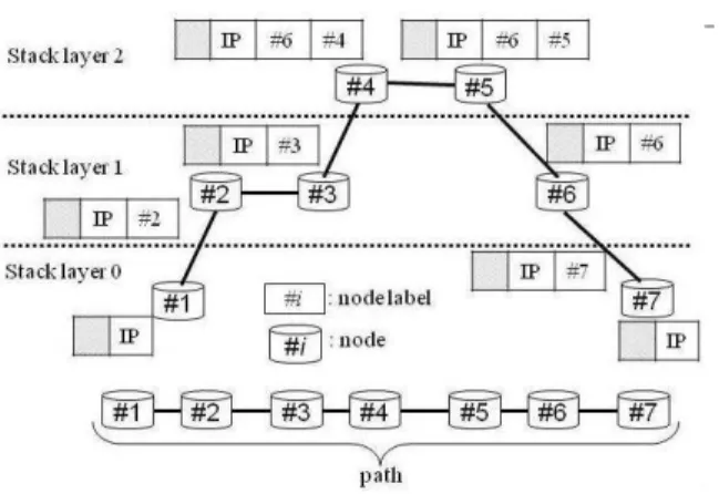
This paper focuses on MPLS for IP-based dedicated ser-vices. MPLS is a label-switching technique with an MPLS node for a label switching path (LSP) [4]. Label stacking is an efficient, hierarchical technique of MPLS, as shown in Fig. 2. An ingress node (node#1in Fig. 2)
adds a label (label#2in Fig. 2) and forwards packets to
Figure 3: FLID.
#5: In using the label stack technique, the link stores the corresponding link identifier.
That is, when the route between lh and lk introduces label stacks, lh−1 and lk+1 store the identifiers of lk+1
andlh−1, respectively.
The number of stored link identifiers increases at a link using label stacking when the number of stacks increases. The route between terminals and the terminals contained in a link can be calculated using this path management method.
3.4
Following
node
identifier
(FNID)
method
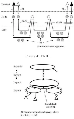
As a basic rule, the terminal stores the identifier of the connected edge node and vice versa. Nodes and links store each other’s corresponding links and nodes. A method where all links store edge node identifiers is pre-sented to meet the requirements of path management, as shown in the following steps and in Fig. 4.
Algorithm 2 (A2)
#1: Store terminal identifiersu1 anduN in node identifiersn1and nN, respectively
#2: Node identifierni stores adjacent link identifiers
li−1 andli (i= 1,2,· · ·, N), wherel0 andlN ={φ}
#3: li stores adjacent node identifiersni andni+1
(i= 1,2,· · ·, N−1)
#4: For anyli (i= 1,2,· · ·, N), store identifier of a pair of{n1 ,nN}
The number of stored terminal identifiers increases at a link when the number of terminals increases. This path management method can be used to calculate the route between terminals and the terminals contained in a link.
Figure 4: FNID.
Figure 5: Layered ring network.
4
Application
to
interconnected
net-works
4.1
Layered ring networks
A telecommunication transport network generally con-sists of access and core networks. An access network is the lowest layer network, while a core network contains several layer networks depending on transmitted traffic volume and area coverage. Furthermore, to assure high reliability with a redundant route, the dedicated services are provided by the network based on a ring topology. Therefore, we assume that a network consists of a lay-ered ring network, as shown in Fig. 5. We apply the label stack technique when the two edge nodes connect through the upper-layer networks, as indicated by label stack arrow#1in Fig. 5.
4.2
New management methods
Generally speaking, the layered ring network has the fol-lowing features.
Proposed algorithm Combination Method (CM):
LetCdefine the boundary layer between upper and lower layers. We apply the following algorithms for a giveni.
1. Ifi≤C, then apply FNID.
2. Ifi > C, then apply FLID. Identifiers stored at the link represent edge nodes in i=C.
3. Managei=C andC+ 1 as follows.
In the case of a network withi=C+ 1, the adjacent boundary link in aCnetwork should be stored at the boundary link. In the case of ani=Cnetwork, both boundary edge nodes in aC+ 1 network should be stored at all corresponding links in theCnetwork.
Let us consider the case of interconnected networks. If we assumeC6= 1, the number of links to search for affected customers is very large. This is because the number of rings in lower-layer networks is much larger than that in upper-layer networks. Therefore, much time will be needed to search for affected customers. Therefore,C = 1 is suitable in interconnected networks to reduce the management work.
4.3
Network model assumptions
Let us make the following assumptions for constructing and evaluating our proposed method by referencing real networks.
• For ”M” as the highest layer, the maximum number of rings in layeriis given by 4M−i.
• 1 ≤ N ≤ 4 for any i where 2 ≤ i ≤ M, that is a ring in Layer 2 or the upper-layer networks has a connection with 4 lower-layer rings.
• 1 ≤N ≤ 10 for i = 1; that is, a ring has 10 edge nodes at most.
• M ≤ 4, which corresponds to 4 layers like the Japanese PSTN.
Let the failure rate of the section be represented by
Pf. Then the failure rate has the following relation-ship.
Σ(Pf)≤1
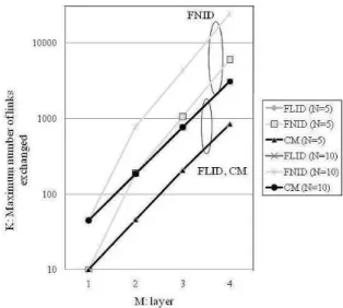
Let us define the number of searched links for affected customers when a section failure occurs as HF LID(l), HF N ID(l), and HCM(l).
(1) Total number of searched links for FLID:
HF LID= Σ(PfHF LID(l))
(2) Total number of searched links for FNID:
HF N ID= Σ(Pf)
(3) Total number of searched links for CM:
HCM= Σl′(Pf) + Σl′′(PfHF LID(l))
The results are compared in Fig. 6. TheHsof all meth-ods increase as M increases. Since H is the number of searched links for affected customers during the observ-ing period, it is necessary that H < 1. HF N ID is the smallest, whileHF LID is very large because of the large number of layer-1 rings. HF LID >1 as M increases, so it is impossible to use it in this situation. Since HCM applies to FNID for layer-1, H < 1 is achieved even in the case of M = 4.
4.5
Evaluation by ease of changing managed
objects
CM is quantitatively compared with FLID and FNID in terms of how easy it is to change managed objects. The following assumptions were made for this evaluation.
• Although it is impossible to know the number of oc-currences of each case during a year, all cases are assumed to have occurred during a year. An end-to-end path was installed in advance among all nodes in layer-1 rings.
Figure 6: Comparison of number of searched links for affected customers.
• The total number of links changed is defined as the link count.
Let us define the total number of links changed as
KF LID, KF N ID, KCM, respectively.
Total number of changed links for FLID:
KF LID= ΣMi=1Ni(Ni−1)/2×4M−i
Total number of changed links for FNID:
KF N ID=N1(N1−1)/2×4M−1+N1(N1−1)×ΠMi=2Ni(Ni−1)/2
Total number of changed links for CM:KCM =KF LID
The results are compared in Fig. 7. TheKsof all meth-ods increased as M increased. KF LID and KCM where the smallest, whileKF N ID was very large because of the large number of links changed. Since the numbers of links changed for KF LID and KCM were much smaller than that of KF N ID, the probability of miss-operation for FLID and CM is small.
Considering both results, CM is far superior to FLID and FNID.
5
Interconnecting procedures
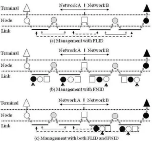
Let us consider interconnecting networks. There are three patterns: (1) both networks are managed by FLID, (2) both networks are managed by FNID and (3) one network is managed by FLID and the other is managed by FNID. The application of each pattern depends on which layers are interconnected. Figure 8 shows the methods in these three cases.
1. Managed with FLID
Figure 7: Comparison of number of changed links.
Figure 8(a) shows both Networks A and B man-aged with FLID. In this case, each boundary link in each network stores adjacent boundary link iden-tifiers. The link in a lower layer of the label stack stores the corresponding link identifier if the con-nected link is in a higher layer of the label stack.
2. Managed with FNID
Figure 8(b) shows both Networks A and B man-aged with FNID. In this situation, all links in both networks between two edge nodes should store both edge node identifiers.
3. Managed with both algorithms
Figure 8(c) shows Network A managed with FLID while Network B managed with FNID. In the case of Network A, the adjacent boundary link in an-other network should be stored at the boundary link. Moreover, the link in a lower layer of the label stack should store the corresponding link identifier, if the connected link is in the higher layer of the label stack. In the case of Network B, all links in Net-work B should store another edge node identifier as additional input.
6
Conclusions
Dedicated services based on MPLS networks will be widely introduced in interconnected networks to meet the demand of enterprise customers. Since end-to-end connection will be more complicated in interconnecting networks, path management will be important to enable quick reaction to failures to ensure customer satisfaction.
Figure 8: Interconnecting procedures.
1. The method in which a link stores an adjacent link identifier and the edge node identifier is stored at an edge link (FLID),
2. The method in which all links store edge node iden-tifiers (FNID).
We assume that the interconnected networks consist of a layered ring network, and a new method applies FNID in lower-layer networks and FLID in upper-layer networks (CM).
CM was evaluated quantitatively in terms of operational cost factors for the ability to search for users whose ser-vice has failed and the ease of changing managed objects in interconnected networks.
A consideration of partial failure of links for these mech-anisms is a topic for further study.
References
[1] “White paper on telecommunications,” pp. 89, 2006.
[2] Ono, K., “Vision of e-VLAN as a wide-area LAN service,”NTT Technical Journal, Vol. 15, No. 1, pp. 15-19 2003
[3] Ohsaki, K., Maeda, Y., Moriya, H., Shimokawa, M., “Constructing technique of IP router networks,”
NTT Docomo Technical Journal, Vol. 12, No. 1, pp. 57-63, 2004
[4] Rosen, E., Viswanathan, A., Callon, R., “Multipro-tocol Label Switching Architecture,” 3031, 2001
[5] Uno, H., Kokubun, T., “A New OSS Architecture to Meet Business Process Changing,”Trans. on IEICE, Vol. J84-B, No. 3, pp.380-391, 2001
No. 8, pp.637-642, 2000