Study on the Distribution of the Magnetic Field of Circular
and Square Exiting Coils in Electromagnetic Flow Meter
Ling-fu Kong 1, Sheng-xue Du 2 and Ying-wei Li 3
1
College of Information Science and Engineering, Yanshan University, Qinhuangdao, Hebei, China
2 College of Information Science and Engineering, Yanshan University, Qinhuangdao, Hebei, China
3
College of Information Science and Engineering, Yanshan University, Qinhuangdao, Hebei, China
Abstract
Exciting coil is an important part of the electromagnetic flow meter, its reasonable design has significant influence on the performance of electromagnetic flow meter. This paper discusses the magnetic field distributions of circular and square exciting coils in electromagnetic flow meter, using Biot-Savart Law and superposition principle, the simulation of magnetic field distribution is done, in the cross section that containing electrodes inside measurement pipe, and two indicators the magnetic induction intensity parallel degree in direction and magnetic induction intensity uniform degree in size is proposed, the analysis and comparison of induced magnetic field generated circular and square exciting coils is done based on above two indicators. This paper provides a reference for the optimal design of exciting coils in electromagnetic flow meter.
Key words: circular, square, exiting coil, magnetic field
distribution, electromagnetic flow meter.
1 Introduction
Electromagnetic flow meter is an instrument
measuring the flow volume of conductive liquid by Faraday's law of induction, it is widely used in
metallurgy, drainage, chemical and petroleum, food-making, medical, environmental protection,
aviation, agriculture irrigation, and so on. It is mainly
composed of a sensor and a converter.
Electromagnetic flow sensor is installed in fluid
transmission process pipe, it converts the flow volume of conductive liquid into induction voltage signal linearly, the converter provides excitation
current to the sensor for generating magnetic field, accepts the induction voltage signal, and processes it
to standard current or voltage signal.
The magnetic field distribution of electromagnetic flow meter causes the attention of researchers. In
1998, A. Michalski etc established 2D model of electromagnetic flow meter by finite element method
[1], studied the optimal design of exciting coil, in order to get the uniform weighting function, making induction voltage signal measured by electrode only
related with the mean flow velocity of fluid. In 2002, A. Michalski etc established the 3D hybrid
mathematical model of exciting coil of
electromagnetic flow meter [2]. XiaoZhang Zhang
studied calculation of magnetic field of
electromagnetic flow meter with large diameter and multi-electrodes by idealized magnet model [3]. Chen
Zhao etc proposed a approximate calculation method for magnetic field distribution of saddle shape exciting coil of electromagnetic flow meter [4].
Wang done numerical simulation and verification of weighting function of electromagnetic flow meter [6].
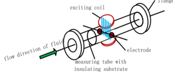
The measurement principle of the electromagnetic flow meter is based on Faraday's law of induction. As
shown in figure 1, while conductivity fluid cut
magnetic field line inside magnetic field
B
of thesensor, induced potential E that is proportional to the fluid velocity v is generated at two electrodes, usually
it is expressed as following formula [7]:
EkBDV (1)
In above formula, k is coefficient of instrument, D is
the inner diameter of sensor pipeline.
flange
electrode
measuring tube with insulating substrate exciting coil
flow direction of fluid
Fig. 1 Measurement principle of electromagnetic flow meter.
The volume flow is determined by the average flow velocity, in a circular pipe the flow volume is as
following:
2
4
QD V (2)
Gained by (1) (2)
4
D
Q E
kB
(3)
When the magnetic induction
B
and the innerdiameter D of the pipeline are constants, the flow
volume Q of fluid is proportional only to induction
potential E, and has nothing to do with other physical parameters (such as density, conductivity, etc), that is
the significant advantage of electromagnetic flow meter.
Above equations simply illustrate the working
principle of electromagnetic flow meter, they are set up only when the following conditions are met: (1) in
the infinite range, the magnetic induction B is evenly distributed; (2) the speed of the fluid is as solid conductor, the internal particle speed is the same
everywhere, and equals to the average velocity.
According to the required magnetic induction in condition (1), to realize the optimal design of exciting
coil of the electromagnetic flow meter, this paper focuses on the analysis of magnetic field distribution
for circular and square exciting coils.
2 Calculation and simulation of magnetic
field distribution of electromagnetic
flow meter
2.1 Calculation of magnetic field distribution of
exciting coil
Basing on Biot-Savart Law, the basic law of magnetic field produced by a current carrying
conductor is: Any current element Id l produce
magnetic inductiond B at any point P in space is as
following:
0 3 4
Id l r d B
r
(4)
In above formula,
r
is the vector from currentelement to point P, d lis the vector of wire element.
The total magnetic induction at point P could be got
through the integral of the magnetic field generated
along the current-carrying conductor.
If d Bis magnetic field generated by a small section
of wire at place
r
, above formula could be wrote as:0 3
4
x y z x y zx y z
i
j
k
I
B
l
l
l
B i
B j
B k
r
r
r
r
(5)
To calculate magnetic field generated by n small
sections of wire at place
r
, it is0 3
1 1 1
( )
4
n n n
xi yi zi xi yi zi
i i i
x y z
i j k I
B l l l B i B j B k
r
r r r
(6)
Above formula can be applied to calculate the magnetic induction produced by arbitrary shape
current at any place.
l
xi,l
yi,l
zimean the componentsof current element along the axis in rectangular
calculation and simulation of the magnetic field distribution of the exciting coil of electromagnetic
flow meter could be done.
2.2 Simulation of magnetic field distribution of
exciting coil
First of all the coordinate system is established, center axis of measuring pipe for z axis, the
connection of geometry centers of two field coils for x axis, the connection of two point electrodes for y
axis. In the rectangular coordinate system, calculation and simulation of magnetic field produced by field coil in measurement pipeline's cross section
containing electrodes, could be done according to the following steps:
1) In x-y plane, the part between two field coils is
meshed, and then coordinate (x, y, 0) of each grid
point is determined;
2)The current carrying conductor is divided into
many small elements, and coordinate (xc, yc, zc) of
every small element and coordinate ( , , )l l lx y z of
every small element vector are determined;
3)Calculating the vector
r
( , , )r r rx y z andcorresponding distance r from each grid point to
small wire elements;
4) Respectively in the x, y direction, calculating the
component Bxi and Byi of magnetic induction
produced at a certain point as following:
0
3( )
4
xi yi z zi y
I
B l r l r
r
, 0
3( )
4
yi zi x xi z I
B l r l r
r
;
5) Calculating the summation of the magnetic induction at a certain point produced by all the small
elements 1
n
x xi
i
B B
, 1n
y yi
i
B B
;6) At each grid point in the given cross section, calculating magnetic induction according to the above steps;
7) Doing simulation, describing the graphics of magnetic strength in given cross section.
In the following content, the part of section between the two field coils is divided into 40 by 40 grids, at each grid point, the simulation of magnetic induction
produced respectively by circular and square field coils is done.
When the shape of magnet coil is circle, the radius of magnet coil is 2.5cm, the turn of each field coil is 6,
and the thickness of each field coil is 2cm, the distance between two field coils is 6cm, current strength is 10mA in coils. In the cross section of
measuring tube containing electrodes, the magnetic field distribution of above circular magnet coils is as
shown in figure 2, the red dot mean intersection of field coils and the cross section.
-15 -10
-5 0
5 10
15
-15 -10 -5 0 5 10 15
-5 0 5
(a) Circular magnet coil
-15 -10 -5 0 5 10 15
-15 -10 -5 0 5 10 15
x
y
(b) Sectional view of magnetic field distribution
Fig.2 Magnetic field distribution of circular magnet coil.
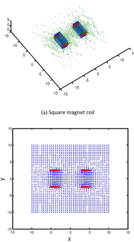
When the shape of magnet coil is square, suppose the
length of square side is 5cm, the turn of each field coil is 6, and the thickness of each field coil is 2cm,
field distribution of above square magnet coils is as shown in figure 3.
-15 -10
-5 0
5 10
15
-15 -10 -5 0 5 10 15
-5 0 5
(a) Square magnet coil
-15 -10 -5 0 5 10 15
-15 -10 -5 0 5 10 15
x
y
(b) Sectional view of magnetic field distribution
Fig.3 Magnetic field distribution of square magnet coil.
3 Magnetic field analysis of field coil
Analysis for the magnetic field distribution of field
coil is done in cross section of measuring tube containing electrodes. In the cross section, the vector
of produced magnetic induction is:Bcx i cy j
3.1 Two indicators for analysis
Because the magnetic induction is a vector, so naturally the indicators for analysis and comparison
of magnetic field include: uniform degree of strength and parallel degree of direction. In the considered cross section including electrodes, the direction of
magnetic induction vector could be represented by
the angle
between magnetic induction vector andpositive direction of x axis as following:
tan cx
cy
, arctancx
cy
(7)
Describing function for parallel degree of field direction is proposed, supposing that at each grid
point, the average of the Angle
kbetween magneticinduction vector and positive direction of x axis is
0,then 0
1
1 n
k k n
. Defining as follows:0 1
0
(| k |)
RM MAX
(8)
2 0 1
1 0
1
( )
1 n
k
k
RD n
(9)1
RM reflects the maximum deviation of field
direction in the area; RD1 reflects the whole parallel
degree of field direction in the region. The smaller
value of RD1, the more ideal the whole parallel
degree of field direction is.
Vector size of magnetic induction could be
represented by length
d
of vector as following:2 2
d
cx
cy
10)Describing function for uniform degree of field strength is proposed, supposing that at each grid point,
the average of the length
d
kof magnetic inductionvector is
d
0, then 01
1
nk k
d
d
n
. By the same token,defining as follows:
0 2
0 (|dk d |)
RM MAX d
(11)
2 0 2
1 0
1
( )
1
n k
k
d d
RD
n d
(12)2
RM reflects the maximum deviation of field
strength in the area;
RD
2 reflects the wholeuniform degree of field strength in the region. The
uniform degree of field strength is.
3.2 Magnetic field analysis of circular and square magnet coils
Based on the above indicators, calculation and
analysis is done for magnetic field distribution of the circular and square magnet coils described in cross section containing electrodes, and the specific
situation is as shown in table 1.
Table 1: Magnetic field distribution of circular and square magnet
coils
Shape of
coil
direction of magnetic induction
0
RM1 RD1
circle 0.0080 195.1070 68.3793
square 0.0078 198.8714 66.3584
Shape of
coil
strength of magnetic induction
0
d
RM2RD
2circle 5.8677e-005 1.4594 0.5036
square 6.2802e-005 1.7527 0.4455
It is known from table 1, that for the whole parallel degree in direction of magnetic induction , the square
magnet coil is better than circular magnet coil, but the maximum deviation is slightly bigger; for the overall
degree of uniformity of field strength, square field coil is better than circular magnet coil, but the maximum deviation is also slightly bigger.
The specific distribution of magnetic induction direction for circular and square magnet coils is
respectively as shown in figure 4 and figure 5.
-3 -2
-1 0
1 2
3
-4 -2 0 2 4 -200 0 200
y x
z
(a) Relative direction of magnetic induction 0
0
k
-3 -2
-1 0
1 2
3
-4 -2 0 2 4 -2 0 2
y x
z
(b) Direction of magnetic induction k
Fig.4 Distribution of magnetic induction direction of circular
magnet coil.
-3 -2 -1 0
1 2 3 -4
-2 0 2 4 -200 -100 0 100 200
y x
z
(a) Relative direction of magnetic induction 0
0 k
-3 -2
-1 0
1 2
3
-4 -2 0 2 4 -2 0 2
y x
z
(b) Direction of magnetic inductionk
Fig. 5 Distribution of magnetic induction direction of square
magnet coil
Contrasting figure 4 and figure 5, it also reflects square field coil is better than circular magnet coil for
the whole parallel degree of magnetic induction direction, which is consistent with the results in table
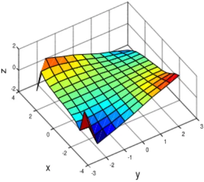
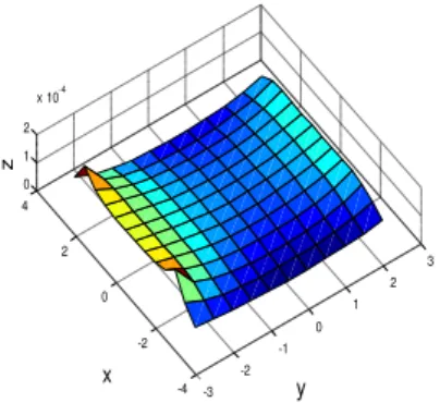
The specific distribution of field strength for circular and square magnet coils is respectively as
shown in figure 6 and figure 7.
-3 -2
-1 0
1 2
3
-4 -2 0 2 4 -2 0 2
y x
z
(a) Relative strength of magnetic induction 0
0
k
d d d
-3 -2
-1 0
1 2
3
-4 -2 0 2 4 0 1 2
x 10-4
y x
z
(b) Strength of magnetic inductiondk
Fig. 6 Strength distribution of magnetic induction of circular
magnet coil
-3 -2
-1 0
1 2
3
-4 -2 0 2 4 -1 0 1 2
y x
z
(a) Relative strength of magnetic induction 0
0
k
d d d
-3 -2
-1 0
1 2
3
-4 -2 0 2 4 0 1 2
x 10-4
y x
z
(b) Strength of magnetic inductiondk
Fig.7 Strength distribution of magnetic induction of square magnet
coil.
Contrasting figure 6 and figure 7, it also reflects square field coil is better than circular magnet coil for
the overall uniform degree of magnetic induction strength, which is also consistent with the results in table 1.
4 Conclusion
In the infinite range, the magnetic induction B is
constant and uniform, which is one of the ideal working conditions for the electromagnetic flow meter. In order to realize reasonable design of field
coil of electromagnetic flow meter, and improve its performance, in this paper basing on Biot-Savart Law
and superposition principle, calculation and
simulation for the magnetic field distribution of circular and square magnet coils is done, in the cross
section containing electrodes of measuring tube. Two indicators for analysis and comparison of magnetic
field distribution are proposed: uniform degree of magnetic induction strength and parallel degree of
field direction. Based on above two indicators, the magnetic field distribution of circular and square magnet coils is analyzed, it shows that: square field
coil is better than circular magnet coil both for the whole parallel degree of magnetic induction direction
and for the overall uniform degree of magnetic induction strength. It could provide certain reference for optimal design of field coil of electromagnetic
References
[1] A. Michalski, and J. Starzynski, “Optimal design of the coils of an electromagnetic flow meter”, IEEE Transactions on Magnetics, Vol.34,No. 5,1998, pp. 2563-2566.
[2] A. Michalski, J. Starzynski, and S. Wincenciak, “3-D approach to designing the excitation coil of an electromagnetic flow meter”, IEEE Transactions on Instrumentation and Measurement, Vol. 51,No. 4, 2002, pp. 833-839.
[3] Xiaozhang Zhang, “Calculation and measurement of the magnetic field in a large diameter electromagnetic flow meter”, ISA Transactions, Vol. 42, 2003, pp. 167-170. [4] Chen Zhao, Bin Li, and Wenjian Chen, “An Algorithm
for Analyzing Magnetic Field Distribution of Saddle Excitation Coils in EM Flowmeter Sensor”, Journal of Shanghai University(Natural Science), Vol. 14, No. 1, 2008, pp. 31-35.
[5] Wadhwa, and Rhythm-Suren, “Electromagnet Gripping
in Iron Foundry Automation Part II: Simulation”, International Journal of Computer Science Issues, Vol. 9, No. 22-2, 2012, pp. 238-243.
[6] Jingzhuo Wang, “Numerical simulation and verification of weight function of electromagnetic flow meter”, Chinese Journal of Scientific Instrument, Vol. 30, No. 1, 2009, pp. 132-137.